EP0260990A2 - Commande de focalisation et indication d'information concernant un objet - Google Patents
Commande de focalisation et indication d'information concernant un objet Download PDFInfo
- Publication number
- EP0260990A2 EP0260990A2 EP87308294A EP87308294A EP0260990A2 EP 0260990 A2 EP0260990 A2 EP 0260990A2 EP 87308294 A EP87308294 A EP 87308294A EP 87308294 A EP87308294 A EP 87308294A EP 0260990 A2 EP0260990 A2 EP 0260990A2
- Authority
- EP
- European Patent Office
- Prior art keywords
- lens system
- distance
- basis
- video camera
- focal length
- Prior art date
- Legal status (The legal status is an assumption and is not a legal conclusion. Google has not performed a legal analysis and makes no representation as to the accuracy of the status listed.)
- Granted
Links
- 230000003287 optical effect Effects 0.000 claims abstract description 38
- 230000004044 response Effects 0.000 claims abstract description 9
- 238000003384 imaging method Methods 0.000 claims abstract description 5
- 238000006243 chemical reaction Methods 0.000 claims description 42
- 238000001514 detection method Methods 0.000 claims description 20
- 238000000034 method Methods 0.000 description 11
- 230000008569 process Effects 0.000 description 11
- 238000010586 diagram Methods 0.000 description 8
- 238000013459 approach Methods 0.000 description 2
- 101150065817 ROM2 gene Proteins 0.000 description 1
- 238000012937 correction Methods 0.000 description 1
- 230000000694 effects Effects 0.000 description 1
- 230000008030 elimination Effects 0.000 description 1
- 238000003379 elimination reaction Methods 0.000 description 1
- 230000006870 function Effects 0.000 description 1
- 230000006872 improvement Effects 0.000 description 1
- 230000007246 mechanism Effects 0.000 description 1
- 238000012986 modification Methods 0.000 description 1
- 230000004048 modification Effects 0.000 description 1
- 230000002265 prevention Effects 0.000 description 1
- 238000012545 processing Methods 0.000 description 1
Images






Classifications
-
- H—ELECTRICITY
- H04—ELECTRIC COMMUNICATION TECHNIQUE
- H04N—PICTORIAL COMMUNICATION, e.g. TELEVISION
- H04N23/00—Cameras or camera modules comprising electronic image sensors; Control thereof
- H04N23/95—Computational photography systems, e.g. light-field imaging systems
- H04N23/958—Computational photography systems, e.g. light-field imaging systems for extended depth of field imaging
- H04N23/959—Computational photography systems, e.g. light-field imaging systems for extended depth of field imaging by adjusting depth of field during image capture, e.g. maximising or setting range based on scene characteristics
-
- H—ELECTRICITY
- H04—ELECTRIC COMMUNICATION TECHNIQUE
- H04N—PICTORIAL COMMUNICATION, e.g. TELEVISION
- H04N23/00—Cameras or camera modules comprising electronic image sensors; Control thereof
- H04N23/60—Control of cameras or camera modules
- H04N23/63—Control of cameras or camera modules by using electronic viewfinders
Definitions
- the present invention relates generally to focusing control and indication of information relating to an object and so on, and may be applicable particularly to video cameras.
- zooming apparatus for allowing selection between an automatic focus mode and a manual focus mode
- zooming apparatus comprises a front lens system, a rear lens system, and a zoom lens system provided therebetween.
- Various types of zooming apparatus have been developed theretofore.
- One previous arrangement is that in the manual focus mode the front lens system is moved in the directions of the axis of the zooming apparatus by manual rotation of a focus ring after the rear lens system is moved to and fixed at a predetermined position and in the automatic focus mode the rear lens system is automatically moved in the same directions after the front lens system is moved up to a predetermined position.
- defocusing does not occur during zooming because the rear lens system is kept at the predetermined position and on the other hand this requires that two focusing mechanisms are provided for the front and the rear lens systems, respectively, resulting in a complex arrangement.
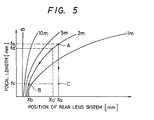
- Fig. 5 is a graphic diagram showing the relationship between the focal length and the rear lens system position on zooming in the focusing state. If taking a picture of an object at 2 meter's distance under the condition that a focal length is fa, the focusing state can be obtained by positioning the rear lens system to xa (point A). When the zoom-down is then performed so that the focal length becomes fc, the rear lens system position is not shifted to xb (point B) and remains at xa (point C), resulting in the off-focusing.
- Such a zooming apparatus in which the focusing operation is affected by moving only the rear lens system has a disadvantage in that it is difficult to accurately indicate the distance to the object because the distance to the focused object is determined by the position of the zoom lens unit besides the rear lens system position. This disadvantage causes a poor operativity.
- an important problem in optical systems relates to the need for focusing control when a conversion lens is mounted thereto.
- the focal length is changed in response to the mounting of a conversion lens such as telephoto conversion lens and wide-angle conversion lens, and therefore this requires to a further adjustment to again bring the object into focus and is troublesome.
- a further improvement would be required from the view point of elimination of the additional trouble and accurate image pickup.
- a video camera with an optical system including a zoom lens system and a rear lens system provided therebetween wherein focusing is performed by varying the distance between the rear lens system and an imaging pickup device of the video camera comprising: first sensor means for sensing the position of the rear lens system to detect a relative distance between the rear lens system and the image pickup device and for producing a first detection signal indicative of the detected relative distance; second sensor means for sensing the position of the zoom lens system to detect a focal length of the optical system and for producing a second detection signal indicative of the detected focal length; drive means for driving the rear leans system; and control means responsive to the first and second detection signals from the first and second sensor means for calculating a distance to an object on the basis of the detected relative distance and the detected focal length, detecting a zooming operation of the optical system on the basis of the second signal produced by the second sensor means, and, in response to the detection of the zooming operation, calculating a relative distance between the rear lens system and the image pickup device on the basis of the
- the video camera further includes second control means for detecting the attachment of a conversion lens to said optical system, reading information relating to the attached conversion lens, and producing a second control signal on the basis of the read information to supplying it to the drive means so that the position of the rear lens system is controlled to bring the optical system with the conversion lens into the focus state.
- the second control means calculates a resultant focal length of the optical system and the conversion lens on the basis of the magnification of the conversion lens and determines the controlled amount of the rear lens system on the basis of the calculated resultant focal length.
- the video camera has indication means for indicating the distance to the object calculated by the control means.
- the video camera further includes third sensor means for sensing a lens opening degree of the optical system to generate a third detection signal indicative of the sensed opening degree and second control means responsive to the first to third detection signals for calculating a depth of field to produce a signal indicative of the calculated depth of field.
- the indication means further indicates the calculated depth of field in response to the signal from the second control means.
- a zooming apparatus including an optical lens system 30 which comprises a front lens system 30a, a zoom lens system 30b and a rear lens system 30c.
- the optical lens system 30 is optically coupled to an image pickup device 3l such as charge-coupled device (CCD), so that a light beam having optical information relating to an object taken by the video camera reaches the image pickup device 3l after passed through the optical lens system 30 and an image is focussed thereon.
- the image pickup device 3l generates an electrical signal by optoelectric conversion and the produced electrical signal is supplied to a video circuit 32 where a video signal is produced.
- the relationship between the object VI and the image VII is as shown in Fig. 2 wherein the references Hl and H2 respectively represent first and second principal points, hl and h2 respectively represent first and second principal planes, Fl and F2 respectively designate first and second focal points, f is the focal length, xl represents the distance from the first focal point Fl to the object VI, x2 is the distance from the second focal point F2 to the image VII, and U is the distance to the object VI, i.e., the distance between the object VI and the imaged position.
- the value x2 corresponds to the movement distance of the rear lens system 30c with respect to the image pickup device 3l, i.e., the relative distance between the rear lens system 30c and the image pickup device 3l, and hence is hereinafter referred to as the movement distance x2 of the rear lens system 30c.
- a first position sensor illustrated at 33 detects the position of the rear lens system 30c to generate a first detection signal indicative of a movement distance x2 of the rear lens system 30c, i.e., the relative distance between the rear lens system 30c and the image pickup device 3l, and the generated first detection signal is supplied to an arithmetic unit 34.
- a second position sensor illustrated at 35 detects the position of the zoom lens system 30b and generates a second detection signal representative of the focal length f, which is varied in accordance with the position of the zoom lens system 30b. The generated second detection signal is also supplied to the arithmetic unit 34.
- the respective first and second position sensors 33, 35 may comprise potentiometer-type trnasducers, each including a resistor with a continuously adjustable sliding contact, and the output signals thereof are supplied to the arithmetic unit 34 after A/D converted. It is also appropriate that an optical encorder is used for the position sensors 33, 35. In this case, the A/D converter is not required.
- the arithmetic unit 34 is connected to first and second switches 36 and 37 for manual focusing whereby the rear lens system 30c is movable in the directions of the axis of the optical lens system 30. That is, the arithmetic unit 34, in response to the manipulation of the first or second switch 36, 37, produces a control signal and supplies it to a motor driver 38 to drive a motor 39 so that the rear lens system 30c is moved toward the image pickup device 3l or the zoom lens system 30b to bring the object into focus.
- the arithmatic unit 34 performs calculation of the equation (3) and stores the calculated value of U after the first and second switches 36, 37 are released from the manipulation and further perform calculation of the equation (4) on the basis of the stored value of U and a new data of the focal length f which is derived from a new data of the zoom lens system position at a predetermined time interval during zooming in which the zoom lens system 30b is operated, so that an error signal is produced on the basis of the difference between the rear lens system movement distance x2 obtained by the calculation of the equation (4) and the rear lens system movement distance x2 obtained by the detection of the first position sensor 33 and supplied to the motor driver 38 whereby the off-focusing due to the zooming is corrected.
- a three-dimensional map may be used instead of the calculations the equations (3) and (4) for the purpose of speed-up of the correction.
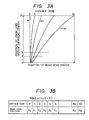
- the three-dimensional map for example, is formed as shown in Fig. 3A wherein the position of the rear lens system 30c is derived from the position of the zoom lens system 30b (divided into 32) with respect to each of 64 divisions between the closest distance and infinite distance to the object.
- a lookup table as shown in Fig. 3B, may be used which is made in accordance with the three-dimensional map of Fig. 3A.
- the lookup table showing the relationship between the distance to the object and the position of the rear lens system is made with respect to each of the 32 focal lengths (32 zoom lens system positions).
- step l0 which is in turn followed by a step ll for initialization.
- step l2 the process advances to a step l2 to read the position of the zoom lens system 30b on the basis of a signal from the position sensor 35.
- the read position (FNEW) is stored in a random access memory of the arithmetic unit 34.
- step l3 is executed to check whether the present zoom lens sytem position (FNEW) is compared with the previous zoom lens system position (FOLD), that is, whether a zooming is performed. This is based on the fact that the zoom lens system 30b is varied in position in response to zooming operation.
- step l4 the process goes to a step l4 to check whether the video camera is in the automatic focus mode. If so, the automatic focusing process is executed in a step l5 so that motor control is performed in accordance with the result of the automatic focusing process in a step l6. If not, that is, if the video camera is in the manual focus mode, the manual focusing process is performed in a step l7 and motor control is effected in accordance with the result of the manual focusing process in a step l8.
- step l9 to read the position of the rear lens system 30c on the basis of a signal from the position sensor 33 and then to a step 20 to calculate a distance U to the object on the basis of the positions of the rear lens system 30c and the zoom lens system 30b, i.e., the relative distance x2 therebetween. If required, the distance U is indicated in a step 2l.
- the operational flow then returns to the step l2.
- FNEW is not equal to FOLD, that is, when a zooming operation is performed
- the process goes to a step 22 where calculation is made in accordance with the equation (4) in order to produce an error signal for moving the rear lens system 30c in the focus position.
- the movement of the rear lens system 30c is performed in a step 23 and in a step 24 the zoom lens system position (FNEW) is stored as the previous zoom lens system position (FOLD) in the RAM of the arithmetic unit 34.
- the operational flow returns to the step l2.
- a focus control circuit 42 with a known arrangement derives the high-frequency component of the video signal from the video circuit 32 to produce an error signal for moving the rear lens system 30c in the direction in which the high-frequency component is increased and to supply the error signal to a terminal a of a switch 43 in the automatic focus mode.
- a terminal b thereof is supplied the error signal produced by the arithmetic unit 34, and the switch 43 performs the switching operation between the automatic focus mode and the manual focus mode in accordance with a control signal supplied from a selection circuit, not shown, through a terminal 44. Therefore, in either focus mode the error signal is supplied to the motor driver 38.
- the apparatus operates as the same as that shown in Fig. l.
- Fig. 7 is a block diagram showing a second embodiment of a zooming apparatus according to the present invnetion which is capable of accurately indicating the distance to an object irrespective of zooming operation in which parts corresponding to those in Figs. l and 6 are marked with the same numerals and the description thereof will be omitted.
- the essential difference between the Fig. 6 zooming apparaus and the Fig. 7 zooming apparatus is that there is further provided an indication system comprising an indication drive circuit 45 and an indication device 46.
- Illustrated at numeral 40 is a potentiometer-type volume unit 40 for manual focus mode in which the output voltage is varied in accordance with the position of a contact 40a thereof.
- the output of the volume unit 40 is converted in an analog-to-digital converter 47 into a digital signal which is in turn supplied to the arithmetic unit 34.
- a switch 4l is provided for selection between the signal from the A/D converter 47 and the signal from the focus control circuit 42, i.e., switching operation between the automatic focus mode and the manual focus mode.
- step 50 the process advances to a step 5l to read the position (FNEW) of the zoom lens system 30b on the basis of a signal from the position sensor 35.
- the step 53 is followed by a step 54 in order to check whether the video camera is in the automatic focus mode or the manual focus mode.
- This decision is made in accordance with detection of manipulation of the switch 4l. If it is in the automatic focus mode, an error signal from the focus control circuit 42 is read in a step 55, followed by a step 56 to produce a motor control signal and to supply it to the motor drive 38. Thereafter, the position (XNEW) of the rear lens system 30c is read on the basis of a signal from the position sensor 33 in a step 57 and the distance U to the object is calculated on the basis of the zoom lens system position (FNEW) in the step 5l and the rear lens system position (XNEW) in the step 57, that is, the calculation of the equation (3) is performed. The calculated distance U to the object is indicated in a step 59.
- the indication drive circuit 45 produces an indication signal which is in turn supplied to the indication device 46 where indication is performed as shown in Figs. 9A to 9D, for example.
- Fig. 9A shows an example in which the indication device 46 is made up of a seven-segment LED device
- Fig. 9B shows an example in which it is made up of a meter-type indicator
- Figs. 9C and 9D respectively show examples in which a plurality of indication elements (LED) are prepared and one indication element is energized in accordance with the calculated distance U, that is, the arithmetic unit 34 generates a control signal from one of ports which is selected in accordance with the value of the distance U and a LED coupled thereto is energized through a LED driver.
- LED indication elements
- a step 60 is executed to obtain the rear lens system movement position x2 which corresponds to the constant position of the volume 40 read in the step 53, followed by a step 6l in which an error signal is produced on the basis of the difference between the obtained rear lens system movement distance x2 and the rear lens system movement distance acquired on the basis of a signal from the position sensor 33.
- a step 6l is executed to produce a motor control signal to bring the rear lens system 30c in the focus position and a step 62 is then executed to calculate the distance U on the basis of the zoom lens system position (FNEW) (focal length) and the rear lens system position (XNEW) (rear lens system movement distance) in accordance with the equation (3).
- FNEW zoom lens system position
- XNEW rear lens system position
- an indication signal indicative of the calculated distance U is produced and supplied to the indication drive circuit.
- a step 64 is executed to measure the position (XOLD) of the rear lens system 30c on the basis of a signal from the position sensor 33, and a step 65 is executed to perform the calculation of the equation (4) using the distance U to the object acquired in the step 58 or 62 and the rear lens system position in the step 64 to acquire the rear lens system movement distance x2.
- the process advances to a step 66 in which an error signal is produced on the basis of the acquired rear lens system movement distance x2 and the value acquired by the detection signal of the position sensor 33 so as to bring the rear lens system 30c in the focus position.
- the position of the zoom lens system 30b is stored as the previous value (FOLD). According to this embodiment, the off-focusing due to zooming is corrected and therefore the indication of the distance to the object is made possible.
- Fig. l0 is an illustration of a third embodiment of a zooming apparatus according to the present invnetion.
- This embodiment shown in Fig. l0 is similar to the Fig. 7 embodiment with the exception that the distance range in which a clear image can be obtained is indicated in an electronic viewfinder 49. Parts corresponding to those in Fig. 7 are marked with the same numerals and the description thereof are omitted.
- a diaphram sensor 50 is further provided to detect the opening degree of a diaphram 5l of the video camera to generate a signal indicative of the lens opening value, the lens opening indicating signal being supplied to the arithmetic unit 34 after analog-to-digital converted.
- the diaphram sensor 50 may be of the Hall-generator type which is known in the art.
- the arithmetic unit 34 in the above-mentioned step 59 or 63, derives the depth of focus from the sensed lens opening value and the focal length obtained on the basis of the sensed zoom lens system position and calculates the depth of field, in which an image is focused and sharpness is not lost, on the basis of the previously obtained distance U to the object and the derived focus depth.
- the arithmetic unit 34 generates a signal representative of the calculated field depth and supplies it to an indication signal generator 45 ⁇ which in turn produces an indication signal to supply it to a mixer circuit 48.
- the indication signal generator 45 ⁇ is made up of an indication integrated circuit (for example, Matsushita MNl237A) which is enabled in response to an encoded signal of the distance U.
- the mixer circuit adds the indication signal to the image signal supplied from the video circuit 32 and the mixed signal is supplied to the electronic viewfinder 49.
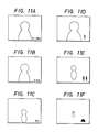
- Fig. llA shows an example in which a depth of field (2 to l.5 m) is indicated therein and
- Figs. llB, llC show examples in which a distnace U to the object is merely indicated therein.
- llD to llF show the case that an image corresponding to the distance U is made therein.
- the distance range is from l to 2 m
- the image is made as shown in Fig. llD
- if it is 2 to 5 m the image is made as shown in Fig. llE
- if it is 5 to the infinite distance the image is made as shown in Fig. llF.
- U2 g2(x + e, f) ......... whil (6)
- Ul is the minimum distance to the object
- U2 is the maximum distance to the object
- x is the distance between the second principal surface of the lens and the imaging surface
- e depth of focus
- f the focal length.
- D f/F where F represents a F-number of the lens which can be measured by an iris encoder
- Fig. l2 is a block diagram showing a fourth embodiment of the present invention which compensates for variation of the focal length appeared when a conversion lens such as telephoto conversion lens and wide-angle conversion lens is attached to the optical system of the video camera.
- the optical system 2 comprises a first lens system l0 and a second lens system 3 which is provided behind the first lens system, the second lens system 3 being arranged so as to be moved in the directions of the optical axis of the optial system, indicated by an arrow A in the figure, by means of a pulse motor 4.
- the light from the object reaches an image pickup device ll which in turn produces an image signal Sl.
- the produced image signal Sl is supplied through a preamplifier l2 to a camera circuit l3 and further to a viewfinder 49.
- a control unit l including a microcomputer comprising a central processing unit (CPU) is provided for controlling the position of the second lens system 3 in response to variation of the focal length f of the optical system 2, i.e., supplies a control signal S2 to the pulse motor 4 so that focusing is performed, the control signal S2 being produced in accordance with information from a conversion lens unit 7 which is adapted to be detachably attached to the optical system 2.
- the conversion lens unit 7 comprising a conversion lens 5 and a read-only memory 6 for storing information, such as identification code and magnification, relating to the used conversion lens 5.
- an output terminal l5 connected to the ROM 6 is coupled to an input terminal l6 which is connected to the control unit 6.
- the control unit l reads the identification code stored in the ROM 6 and refers to the identification code by using a table stored in a ROM l of the control unit l so as to check whether the attached conversion lens 5 is a previously entered conversion lens. If so, the control unit l further reads the magnification Dn stored in the ROM 6 and performs the focusing control in accordance with a program stored in a ROM2.
- the control unit l supplies the control signal S2 to the pulse motor 4 so that the second lens system 3 is moved by ⁇ x and reaches the position Pl.
- the control unit l calculates the depth of field (Ul, U2) on the basis of the depth of focus as described above, and supplies an indication signal to the fiewfiner 49 so that the depth of field is indicated therein.
- the information relating the conversion lens is stored in the ROM 6 of the conversion lens unit 7, it is also appropirate that, as illustrated in Figs. l3A and l3B, the connection between specific two contacts of the input terminal l6 is made in accordance with the type of the conversion lens when the conversion lens unit is attached to the optical system of the video camera and the control unit determines the type of the conversion lens by referring to the connection information by using a table stored in a ROM.
- Fig. l3A shows the case that a conversion lens A is attached to the optical system of the video camera.
Landscapes
- Engineering & Computer Science (AREA)
- Multimedia (AREA)
- Signal Processing (AREA)
- Computing Systems (AREA)
- Theoretical Computer Science (AREA)
- Lens Barrels (AREA)
Applications Claiming Priority (6)
| Application Number | Priority Date | Filing Date | Title |
|---|---|---|---|
| JP220540/86 | 1986-09-18 | ||
| JP61220540A JP2605697B2 (ja) | 1986-09-18 | 1986-09-18 | ビデオカメラ |
| JP234953/86 | 1986-10-02 | ||
| JP234954/86 | 1986-10-02 | ||
| JP61234953A JPS6388533A (ja) | 1986-10-02 | 1986-10-02 | レンズシステムの被写体距離表示装置 |
| JP61234954A JPS6388534A (ja) | 1986-10-02 | 1986-10-02 | ズ−ムレンズシステム |
Publications (3)
| Publication Number | Publication Date |
|---|---|
| EP0260990A2 true EP0260990A2 (fr) | 1988-03-23 |
| EP0260990A3 EP0260990A3 (en) | 1988-10-05 |
| EP0260990B1 EP0260990B1 (fr) | 1992-01-22 |
Family
ID=27330458
Family Applications (1)
| Application Number | Title | Priority Date | Filing Date |
|---|---|---|---|
| EP87308294A Expired - Lifetime EP0260990B1 (fr) | 1986-09-18 | 1987-09-18 | Commande de focalisation et indication d'information concernant un objet |
Country Status (3)
| Country | Link |
|---|---|
| US (1) | US4748509A (fr) |
| EP (1) | EP0260990B1 (fr) |
| DE (1) | DE3776243D1 (fr) |
Cited By (3)
| Publication number | Priority date | Publication date | Assignee | Title |
|---|---|---|---|---|
| EP0335656A1 (fr) * | 1988-03-29 | 1989-10-04 | Sony Corporation | Appareil de focalisation automatique |
| EP0343016A3 (en) * | 1988-05-20 | 1990-09-19 | Victor Company Of Japan, Limited | Automatic focusing system for use in cameras having zoom function |
| DE4326898A1 (de) * | 1993-08-11 | 1995-02-16 | Thomson Brandt Gmbh | Verfahren zur Auswertung von erfaßten Bildsignalen für eine Bildschärfenanzeige |
Families Citing this family (38)
| Publication number | Priority date | Publication date | Assignee | Title |
|---|---|---|---|---|
| JPH07113961B2 (ja) * | 1985-08-05 | 1995-12-06 | キヤノン株式会社 | 信号処理装置 |
| US5446494A (en) * | 1986-03-04 | 1995-08-29 | Canon Kabushiki Kaisha | Focus detecting system |
| US4935763A (en) * | 1987-02-02 | 1990-06-19 | Minolta Camera Kabushiki Kaisha | Camera having a zoom lens unit |
| JP2505192B2 (ja) * | 1987-03-10 | 1996-06-05 | オリンパス光学工業株式会社 | ズ−ム機構 |
| US4951075A (en) * | 1988-01-08 | 1990-08-21 | Minolta Camera Kabushiki Kaisha | Zoom camera |
| US5408332A (en) * | 1988-03-18 | 1995-04-18 | Hitachi, Ltd. | Focusing apparatus for video camera or the like |
| DE3810504A1 (de) * | 1988-03-28 | 1989-10-19 | Chinon Ind Inc | Scharfstellvorrichtung fuer zoomobjektive |
| JPH0721577B2 (ja) * | 1988-04-28 | 1995-03-08 | キヤノン株式会社 | 光学機器 |
| US5369461A (en) * | 1988-07-29 | 1994-11-29 | Canon Kabushiki Kaisha | Automatic focus adjusting device in camera system |
| JP2773144B2 (ja) * | 1988-08-05 | 1998-07-09 | ミノルタ株式会社 | ズームレンズを備えるカメラ |
| US5258802A (en) * | 1989-04-30 | 1993-11-02 | Minolta Camera Kabushiki Kaisha | Camera system which compensates for defocusing during operation |
| US5204710A (en) * | 1989-06-13 | 1993-04-20 | Minolta Camera Kabushiki Kaisha | Camera having zoom lens system |
| JPH03143173A (ja) * | 1989-10-30 | 1991-06-18 | Toshiba Corp | ビデオ・カメラの自動焦点調節装置 |
| JPH03215840A (ja) * | 1990-01-19 | 1991-09-20 | Nippon Philips Kk | カメラ装置用の焦点制御装置 |
| JP2833169B2 (ja) * | 1990-07-18 | 1998-12-09 | 日本ビクター株式会社 | 撮像装置 |
| JPH0575966A (ja) * | 1990-12-13 | 1993-03-26 | Nikon Corp | 電子スチルカメラ |
| JP3082309B2 (ja) * | 1991-05-31 | 2000-08-28 | 日本ビクター株式会社 | オートフォーカス撮像装置 |
| US5315341A (en) * | 1991-12-18 | 1994-05-24 | Eastman Kodak Company | Method and apparatus for through-the-lens distance determination |
| JP2963006B2 (ja) * | 1994-06-01 | 1999-10-12 | 三洋電機株式会社 | カメラ装置 |
| JPH0933791A (ja) * | 1995-07-21 | 1997-02-07 | Sony Corp | レンズ駆動装置及び撮像装置 |
| JPH11127376A (ja) * | 1997-10-20 | 1999-05-11 | Fuji Photo Optical Co Ltd | テレビカメラのレンズ装置 |
| US6954313B2 (en) * | 2002-10-22 | 2005-10-11 | Canon Kabushiki Kaisha | Optical apparatus and lens apparatus |
| US7340109B2 (en) * | 2003-09-30 | 2008-03-04 | Fotonation Vision Limited | Automated statistical self-calibrating detection and removal of blemishes in digital images dependent upon changes in extracted parameter values |
| US7676110B2 (en) * | 2003-09-30 | 2010-03-09 | Fotonation Vision Limited | Determination of need to service a camera based on detection of blemishes in digital images |
| US7590305B2 (en) | 2003-09-30 | 2009-09-15 | Fotonation Vision Limited | Digital camera with built-in lens calibration table |
| US8369650B2 (en) | 2003-09-30 | 2013-02-05 | DigitalOptics Corporation Europe Limited | Image defect map creation using batches of digital images |
| US7295233B2 (en) * | 2003-09-30 | 2007-11-13 | Fotonation Vision Limited | Detection and removal of blemishes in digital images utilizing original images of defocused scenes |
| US7369712B2 (en) * | 2003-09-30 | 2008-05-06 | Fotonation Vision Limited | Automated statistical self-calibrating detection and removal of blemishes in digital images based on multiple occurrences of dust in images |
| US7424170B2 (en) | 2003-09-30 | 2008-09-09 | Fotonation Vision Limited | Automated statistical self-calibrating detection and removal of blemishes in digital images based on determining probabilities based on image analysis of single images |
| US7308156B2 (en) * | 2003-09-30 | 2007-12-11 | Fotonation Vision Limited | Automated statistical self-calibrating detection and removal of blemishes in digital images based on a dust map developed from actual image data |
| US7310450B2 (en) | 2003-09-30 | 2007-12-18 | Fotonation Vision Limited | Method of detecting and correcting dust in digital images based on aura and shadow region analysis |
| WO2007095556A2 (fr) | 2006-02-14 | 2007-08-23 | Fotonation Vision Limited | Dispositif d'acquisition d'image numérique comportant une fonction intégrée de détection et de cartographie de poussières |
| US9380292B2 (en) | 2009-07-31 | 2016-06-28 | 3Dmedia Corporation | Methods, systems, and computer-readable storage media for generating three-dimensional (3D) images of a scene |
| US9344701B2 (en) * | 2010-07-23 | 2016-05-17 | 3Dmedia Corporation | Methods, systems, and computer-readable storage media for identifying a rough depth map in a scene and for determining a stereo-base distance for three-dimensional (3D) content creation |
| JP2018200405A (ja) * | 2017-05-29 | 2018-12-20 | セイコーエプソン株式会社 | プロジェクターおよびプロジェクターの制御方法 |
| CN112153271B (zh) * | 2019-06-27 | 2022-05-20 | Oppo广东移动通信有限公司 | 电子设备的光学镜头的控制方法、控制装置及存储介质 |
| CN112379502A (zh) * | 2019-07-29 | 2021-02-19 | Oppo广东移动通信有限公司 | 镜头模组、镜头模组的控制方法、成像装置和电子设备 |
| CN113301256B (zh) * | 2021-05-23 | 2023-12-22 | 成都申亚科技有限公司 | 一种低功耗多目标连续自动监测的摄像模组及其摄像方法 |
Family Cites Families (16)
| Publication number | Priority date | Publication date | Assignee | Title |
|---|---|---|---|---|
| US3076396A (en) * | 1961-03-02 | 1963-02-05 | Schneider Co Optische Werke | Depth-of-field indicator for varifocal objective |
| GB1203057A (en) * | 1967-08-07 | 1970-08-26 | Rank Organisation Ltd | Improvements relating to camera systems |
| US3735686A (en) * | 1970-12-18 | 1973-05-29 | Sidney R Littlejohn & Co Ltd | Camera systems |
| US4043642A (en) * | 1973-03-06 | 1977-08-23 | Canon Kabushiki Kaisha | Zoom lens system having electrical control of moving elements |
| US4161756A (en) * | 1976-03-19 | 1979-07-17 | Jos. Schneider & Co. Optische Werke | Control system for varifocal objective |
| US4083057A (en) * | 1976-11-08 | 1978-04-04 | Honeywell Inc. | Focus size compensation |
| CH621413A5 (fr) * | 1978-01-31 | 1981-01-30 | Bolex Int Sa | |
| DE2937246A1 (de) * | 1978-11-07 | 1980-05-08 | Bolex Int Sa | Kamera |
| JPS566226A (en) * | 1979-06-29 | 1981-01-22 | Nippon Kogaku Kk <Nikon> | Taking magnification imprintable lens |
| JPS57186872A (en) * | 1981-05-13 | 1982-11-17 | Hitachi Ltd | Auto-focusing device of video camera |
| JPS58105139A (ja) * | 1981-12-17 | 1983-06-22 | Minolta Camera Co Ltd | 写真撮影システムのデ−タ取出し方式 |
| US4531158A (en) * | 1982-01-27 | 1985-07-23 | Hitachi, Ltd. | Automatic focusing system for video cameras |
| US4532553A (en) * | 1982-04-02 | 1985-07-30 | Ampex Corporation | Continuous depth of focus control |
| JPS5931932A (ja) * | 1982-08-18 | 1984-02-21 | Hitachi Ltd | ズ−ムレンズ |
| JPS6053907A (ja) * | 1983-09-02 | 1985-03-28 | Canon Inc | 可変焦点距離レンズ装置 |
| JPH07109474B2 (ja) * | 1984-10-31 | 1995-11-22 | 株式会社ニコン | フイルム感度及び閃光有効距離の表示装置 |
-
1987
- 1987-09-17 US US07/098,035 patent/US4748509A/en not_active Expired - Lifetime
- 1987-09-18 DE DE8787308294T patent/DE3776243D1/de not_active Expired - Fee Related
- 1987-09-18 EP EP87308294A patent/EP0260990B1/fr not_active Expired - Lifetime
Cited By (4)
| Publication number | Priority date | Publication date | Assignee | Title |
|---|---|---|---|---|
| EP0335656A1 (fr) * | 1988-03-29 | 1989-10-04 | Sony Corporation | Appareil de focalisation automatique |
| US4992859A (en) * | 1988-03-29 | 1991-02-12 | Sony Corporation | Automatic focus control apparatus using primary color signals |
| EP0343016A3 (en) * | 1988-05-20 | 1990-09-19 | Victor Company Of Japan, Limited | Automatic focusing system for use in cameras having zoom function |
| DE4326898A1 (de) * | 1993-08-11 | 1995-02-16 | Thomson Brandt Gmbh | Verfahren zur Auswertung von erfaßten Bildsignalen für eine Bildschärfenanzeige |
Also Published As
| Publication number | Publication date |
|---|---|
| DE3776243D1 (de) | 1992-03-05 |
| EP0260990B1 (fr) | 1992-01-22 |
| EP0260990A3 (en) | 1988-10-05 |
| US4748509A (en) | 1988-05-31 |
Similar Documents
| Publication | Publication Date | Title |
|---|---|---|
| EP0260990B1 (fr) | Commande de focalisation et indication d'information concernant un objet | |
| US8373792B2 (en) | Autofocus apparatus with correction of focusing data | |
| US5060001A (en) | Optical apparatus | |
| EP0443463B1 (fr) | Caméra | |
| USRE33830E (en) | Auto-focus system for video camera | |
| EP0489892B1 (fr) | Mecanisme d'autofocalisation base sur les contrastes | |
| US7071985B1 (en) | Optical device and method for selecting object of focus | |
| US4912494A (en) | Camera system | |
| US7372486B2 (en) | Photographing apparatus and method of adjusting an image of a photographing object | |
| US20020171750A1 (en) | Camera system, lens apparatus and camera | |
| GB2513980A (en) | A lens apparatus and a camera system | |
| US8320755B2 (en) | Autofocusing zoom lens | |
| JP7271353B2 (ja) | 撮像装置および波長取得方法 | |
| EP0459408B1 (fr) | Appareil pour contrÔler un système optique | |
| EP0685751A1 (fr) | Appareil photographique avec un temps réduit de déplacement du groupe de lentilles arrière lors de l'enclenchement | |
| US5075713A (en) | Focus control system for camera device | |
| US4572643A (en) | Camera capable of operating in an automatic focus adjusting mode and a manual focus adjusting mode | |
| US5315341A (en) | Method and apparatus for through-the-lens distance determination | |
| US5862415A (en) | Auto-focusing camera with panning state detection function | |
| JP4017752B2 (ja) | 撮影レンズの組立時ピント調整方法 | |
| EP0352778A2 (fr) | Dispositif automatique d'ajustement de la focalisation dans un système de caméra | |
| US5748997A (en) | Control method of a zoom lens camera | |
| US5249010A (en) | Apparatus for controlling a zooming optical device | |
| EP0503572B1 (fr) | Appareil de mise au point optique | |
| JP2008040146A (ja) | 光学機器 |
Legal Events
| Date | Code | Title | Description |
|---|---|---|---|
| PUAI | Public reference made under article 153(3) epc to a published international application that has entered the european phase |
Free format text: ORIGINAL CODE: 0009012 |
|
| AK | Designated contracting states |
Kind code of ref document: A2 Designated state(s): DE FR GB |
|
| PUAL | Search report despatched |
Free format text: ORIGINAL CODE: 0009013 |
|
| AK | Designated contracting states |
Kind code of ref document: A3 Designated state(s): DE FR GB |
|
| 17P | Request for examination filed |
Effective date: 19881215 |
|
| 17Q | First examination report despatched |
Effective date: 19910422 |
|
| GRAA | (expected) grant |
Free format text: ORIGINAL CODE: 0009210 |
|
| AK | Designated contracting states |
Kind code of ref document: B1 Designated state(s): DE FR GB |
|
| ET | Fr: translation filed | ||
| REF | Corresponds to: |
Ref document number: 3776243 Country of ref document: DE Date of ref document: 19920305 |
|
| PLBE | No opposition filed within time limit |
Free format text: ORIGINAL CODE: 0009261 |
|
| STAA | Information on the status of an ep patent application or granted ep patent |
Free format text: STATUS: NO OPPOSITION FILED WITHIN TIME LIMIT |
|
| 26N | No opposition filed | ||
| REG | Reference to a national code |
Ref country code: GB Ref legal event code: IF02 |
|
| PGFP | Annual fee paid to national office [announced via postgrant information from national office to epo] |
Ref country code: FR Payment date: 20030909 Year of fee payment: 17 |
|
| PGFP | Annual fee paid to national office [announced via postgrant information from national office to epo] |
Ref country code: GB Payment date: 20030917 Year of fee payment: 17 |
|
| PGFP | Annual fee paid to national office [announced via postgrant information from national office to epo] |
Ref country code: DE Payment date: 20030925 Year of fee payment: 17 |
|
| PG25 | Lapsed in a contracting state [announced via postgrant information from national office to epo] |
Ref country code: GB Free format text: LAPSE BECAUSE OF NON-PAYMENT OF DUE FEES Effective date: 20040918 |
|
| PG25 | Lapsed in a contracting state [announced via postgrant information from national office to epo] |
Ref country code: DE Free format text: LAPSE BECAUSE OF NON-PAYMENT OF DUE FEES Effective date: 20050401 |
|
| GBPC | Gb: european patent ceased through non-payment of renewal fee |
Effective date: 20040918 |
|
| PG25 | Lapsed in a contracting state [announced via postgrant information from national office to epo] |
Ref country code: FR Free format text: LAPSE BECAUSE OF NON-PAYMENT OF DUE FEES Effective date: 20050531 |
|
| REG | Reference to a national code |
Ref country code: FR Ref legal event code: ST |