EP0261021A1 - Druckmittelbehälter mit Anwesenheitsgeber für Flüssigkeit in einer Gaskammer - Google Patents
Druckmittelbehälter mit Anwesenheitsgeber für Flüssigkeit in einer Gaskammer Download PDFInfo
- Publication number
- EP0261021A1 EP0261021A1 EP87402010A EP87402010A EP0261021A1 EP 0261021 A1 EP0261021 A1 EP 0261021A1 EP 87402010 A EP87402010 A EP 87402010A EP 87402010 A EP87402010 A EP 87402010A EP 0261021 A1 EP0261021 A1 EP 0261021A1
- Authority
- EP
- European Patent Office
- Prior art keywords
- pressure tank
- sensor
- tank according
- tubular
- optical
- Prior art date
- Legal status (The legal status is an assumption and is not a legal conclusion. Google has not performed a legal analysis and makes no representation as to the accuracy of the status listed.)
- Granted
Links
- 239000007788 liquid Substances 0.000 title claims abstract description 35
- 230000003287 optical effect Effects 0.000 claims abstract description 79
- 239000000523 sample Substances 0.000 claims abstract description 42
- 239000000463 material Substances 0.000 claims description 15
- 238000004891 communication Methods 0.000 claims description 11
- 238000009434 installation Methods 0.000 claims description 6
- 239000013307 optical fiber Substances 0.000 claims description 4
- 238000006243 chemical reaction Methods 0.000 claims description 2
- 238000006467 substitution reaction Methods 0.000 claims description 2
- 230000005489 elastic deformation Effects 0.000 description 6
- 230000005484 gravity Effects 0.000 description 4
- 208000031968 Cadaver Diseases 0.000 description 3
- 239000000470 constituent Substances 0.000 description 3
- 238000001514 detection method Methods 0.000 description 3
- 239000012530 fluid Substances 0.000 description 3
- 238000002513 implantation Methods 0.000 description 3
- 239000004020 conductor Substances 0.000 description 2
- 229920001971 elastomer Polymers 0.000 description 2
- 239000000806 elastomer Substances 0.000 description 2
- 230000002349 favourable effect Effects 0.000 description 2
- 230000005499 meniscus Effects 0.000 description 2
- 239000002184 metal Substances 0.000 description 2
- 230000035515 penetration Effects 0.000 description 2
- 238000007789 sealing Methods 0.000 description 2
- 238000004026 adhesive bonding Methods 0.000 description 1
- 238000005219 brazing Methods 0.000 description 1
- 230000000295 complement effect Effects 0.000 description 1
- 238000010276 construction Methods 0.000 description 1
- 230000008602 contraction Effects 0.000 description 1
- 238000005520 cutting process Methods 0.000 description 1
- 230000007547 defect Effects 0.000 description 1
- 230000001627 detrimental effect Effects 0.000 description 1
- 238000009792 diffusion process Methods 0.000 description 1
- 238000006073 displacement reaction Methods 0.000 description 1
- 229940082150 encore Drugs 0.000 description 1
- 239000002360 explosive Substances 0.000 description 1
- 239000011521 glass Substances 0.000 description 1
- 239000003292 glue Substances 0.000 description 1
- 239000002654 heat shrinkable material Substances 0.000 description 1
- 238000002347 injection Methods 0.000 description 1
- 239000007924 injection Substances 0.000 description 1
- 230000009545 invasion Effects 0.000 description 1
- 238000002955 isolation Methods 0.000 description 1
- 230000033001 locomotion Effects 0.000 description 1
- 238000000034 method Methods 0.000 description 1
- 239000000203 mixture Substances 0.000 description 1
- 230000003071 parasitic effect Effects 0.000 description 1
- 230000000149 penetrating effect Effects 0.000 description 1
- 230000035699 permeability Effects 0.000 description 1
- 230000000750 progressive effect Effects 0.000 description 1
- 230000000284 resting effect Effects 0.000 description 1
- 239000000126 substance Substances 0.000 description 1
- 229920002994 synthetic fiber Polymers 0.000 description 1
- 238000003466 welding Methods 0.000 description 1
- 238000009736 wetting Methods 0.000 description 1
Images

Classifications
-
- F—MECHANICAL ENGINEERING; LIGHTING; HEATING; WEAPONS; BLASTING
- F15—FLUID-PRESSURE ACTUATORS; HYDRAULICS OR PNEUMATICS IN GENERAL
- F15B—SYSTEMS ACTING BY MEANS OF FLUIDS IN GENERAL; FLUID-PRESSURE ACTUATORS, e.g. SERVOMOTORS; DETAILS OF FLUID-PRESSURE SYSTEMS, NOT OTHERWISE PROVIDED FOR
- F15B1/00—Installations or systems with accumulators; Supply reservoir or sump assemblies
- F15B1/02—Installations or systems with accumulators
- F15B1/04—Accumulators
- F15B1/08—Accumulators using a gas cushion; Gas charging devices; Indicators or floats therefor
-
- F—MECHANICAL ENGINEERING; LIGHTING; HEATING; WEAPONS; BLASTING
- F15—FLUID-PRESSURE ACTUATORS; HYDRAULICS OR PNEUMATICS IN GENERAL
- F15B—SYSTEMS ACTING BY MEANS OF FLUIDS IN GENERAL; FLUID-PRESSURE ACTUATORS, e.g. SERVOMOTORS; DETAILS OF FLUID-PRESSURE SYSTEMS, NOT OTHERWISE PROVIDED FOR
- F15B2201/00—Accumulators
- F15B2201/20—Accumulator cushioning means
- F15B2201/205—Accumulator cushioning means using gas
-
- F—MECHANICAL ENGINEERING; LIGHTING; HEATING; WEAPONS; BLASTING
- F15—FLUID-PRESSURE ACTUATORS; HYDRAULICS OR PNEUMATICS IN GENERAL
- F15B—SYSTEMS ACTING BY MEANS OF FLUIDS IN GENERAL; FLUID-PRESSURE ACTUATORS, e.g. SERVOMOTORS; DETAILS OF FLUID-PRESSURE SYSTEMS, NOT OTHERWISE PROVIDED FOR
- F15B2201/00—Accumulators
- F15B2201/30—Accumulator separating means
- F15B2201/31—Accumulator separating means having rigid separating means, e.g. pistons
-
- F—MECHANICAL ENGINEERING; LIGHTING; HEATING; WEAPONS; BLASTING
- F15—FLUID-PRESSURE ACTUATORS; HYDRAULICS OR PNEUMATICS IN GENERAL
- F15B—SYSTEMS ACTING BY MEANS OF FLUIDS IN GENERAL; FLUID-PRESSURE ACTUATORS, e.g. SERVOMOTORS; DETAILS OF FLUID-PRESSURE SYSTEMS, NOT OTHERWISE PROVIDED FOR
- F15B2201/00—Accumulators
- F15B2201/30—Accumulator separating means
- F15B2201/315—Accumulator separating means having flexible separating means
- F15B2201/3152—Accumulator separating means having flexible separating means the flexible separating means being bladders
-
- F—MECHANICAL ENGINEERING; LIGHTING; HEATING; WEAPONS; BLASTING
- F15—FLUID-PRESSURE ACTUATORS; HYDRAULICS OR PNEUMATICS IN GENERAL
- F15B—SYSTEMS ACTING BY MEANS OF FLUIDS IN GENERAL; FLUID-PRESSURE ACTUATORS, e.g. SERVOMOTORS; DETAILS OF FLUID-PRESSURE SYSTEMS, NOT OTHERWISE PROVIDED FOR
- F15B2201/00—Accumulators
- F15B2201/40—Constructional details of accumulators not otherwise provided for
- F15B2201/41—Liquid ports
-
- F—MECHANICAL ENGINEERING; LIGHTING; HEATING; WEAPONS; BLASTING
- F15—FLUID-PRESSURE ACTUATORS; HYDRAULICS OR PNEUMATICS IN GENERAL
- F15B—SYSTEMS ACTING BY MEANS OF FLUIDS IN GENERAL; FLUID-PRESSURE ACTUATORS, e.g. SERVOMOTORS; DETAILS OF FLUID-PRESSURE SYSTEMS, NOT OTHERWISE PROVIDED FOR
- F15B2201/00—Accumulators
- F15B2201/40—Constructional details of accumulators not otherwise provided for
- F15B2201/415—Gas ports
-
- F—MECHANICAL ENGINEERING; LIGHTING; HEATING; WEAPONS; BLASTING
- F15—FLUID-PRESSURE ACTUATORS; HYDRAULICS OR PNEUMATICS IN GENERAL
- F15B—SYSTEMS ACTING BY MEANS OF FLUIDS IN GENERAL; FLUID-PRESSURE ACTUATORS, e.g. SERVOMOTORS; DETAILS OF FLUID-PRESSURE SYSTEMS, NOT OTHERWISE PROVIDED FOR
- F15B2201/00—Accumulators
- F15B2201/50—Monitoring, detection and testing means for accumulators
- F15B2201/505—Testing of accumulators, e.g. for testing tightness
Definitions
- the present invention relates generally to pressure tanks, that is to say tanks capable of confining at least one fluid under pressure.
- They can be both pressure accumulators and pressure transmitters.
- the present invention relates more particularly to those of these pressure tanks which comprise, in an envelope, in practice an envelope of rigid material, a separator, which divides said envelope into two chambers of variable volume, namely a liquid chamber and a chamber. of gas, said envelope corollarily comprising, at a distance from each other, two orifices, namely a liquid orifice and a gas orifice, with which said liquid chamber and said gas chamber are each in communication respectively, and which, at least transversely with respect to said envelope, has a wall, called hereinafter for the sake of convenience, transverse wall, spaced both from one and from the other of said orifices and mounted movably in said envelope.
- This separator can for example be constituted by a bladder of flexible material, the opening of which surrounds one of the two orifices, in practice the gas orifice; in this case, it is the bottom of this bladder which forms what is here agreed to be called the transverse wall of the separator.
- this separator can be constituted by a piston; in this case, it is this piston which forms the transverse wall, the separator reducing itself to such a transverse wall.
- the separator used is intended to isolate from one another the two fluids present within the pressure tank concerned, a gas on the one hand, and a liquid on the other hand.
- the separator when the separator is a bladder, there can be a local rupture of this bladder, or, when the liquid in play is a chemical which is relatively aggressive with regard to its constituent material, it can intervene, over time, permeability of this bladder causing diffusion of this liquid through its wall.
- the separator when the separator is a piston, there may be a leak between this piston and the envelope in which it is slidably mounted.
- the pressure tank is arranged vertically with its gas orifice upwards, the sensor thus implemented only intervenes when the gas chamber is completely invaded by the liquid, which, for the circuit of use concerned, may already be too late.
- the senor used operating by capacitance or inductance it has a non-negligible size, in particular in diameter, which can make it technically difficult to install, and, by its very principle, it requires a large volume of liquid before delivering a significant signal.
- the present invention generally relates to a provision advantageously allowing, and in a particularly reduced diameter space, a much faster detection of a defect leading to penetration of liquid into the gas chamber.
- a pressure tank of the kind comprising, in an envelope having at a distance from each other two orifices, namely a liquid orifice and a gas orifice, on the one hand, a separator, which divides said envelope into two chambers of variable volume, namely a liquid chamber and a gas chamber, with which each of said orifices is respectively in communication, and which, at least transversely with respect to said envelope, has a wall, here called for simple convenience, transverse wall, spaced both from one and from the other of said orifices, and movably mounted in said envelope, and, on the other hand, a sensor sensitive to the presence of liquid, which, by means of an opening in the envelope in communication with the gas chamber, extends into said gas chamber, this pressure tank being in a way general characterized in that, at least for the resting configuration, when empty, of the transverse wall of the separator, the sensitive end of said sensor is closer to said transverse wall than to the orifice of the envelope through which it extend
- the desired fault detection can take place much more quickly.
- the senor is an optical probe comprising an optical conduit, which is itself formed of one or more optical fibers, and the internal end of the envelope forms the sensitive end, while its other end is intended to be in connection with a signal processing device, either in the immediate vicinity of the pressure tank, or largely at a distance therefrom.
- Such an optical probe thus finds a particularly satisfactory application to pressure reservoirs, on the one hand because of the relative elastic deformation capacity of the material usually constituting its optical conduit, and on the other hand because the very small overall dimensions of the latter.
- this optical probe is advantageously able to absorb by itself the displacements of the transverse wall of the separator as well when it is constituted by a bladder only when it is constituted by a piston.
- the optical probe is reduced to a section of optical conduit which, apart from the arrow of which it may be the object, is substantially rectilinear.
- the optical probe used according to the invention preferably forms at least one helical turn, and, in the vicinity of its sensitive end, it is coupled, in practice by rotary means , said piston.
- the optical conduit that this optical probe comprises is preferably, over at least part of its length, jacketed by a sheath, and, for example, by a sheath made of material retractable, which, in addition to the protection provided, advantageously makes it possible to adjust the elastic deformation capacity in a suitable manner, in addition avoiding that it can take too sharp a curvature, detrimental to its longevity, upon entering the chamber of gas concerned.
- the sensitive end of the optical probe thus forming the sensor used according to the invention is surrounded by a tubular cage, being disposed radially away from the wall lateral thereof and axially set back relative to its outlet.
- This tubular cage advantageously protects the sensitive end of the probe during the manipulations necessary for the installation thereof, and it then advantageously protects it from any parasitic contact with the separator, which avoids the incidence of possible traces of liquid on the surface thereof, while leaving free access to said sensitive end for such a liquid when it is present in the gas chamber concerned other than in the form of such traces.
- This combination of means is therefore particularly favorable to the arrangement, according to the invention, of the sensitive end of this optical probe near the transverse wall of the separator.
- the implantation in a pressure tank, of the optical probe forming the sensor used according to the invention is advantageously facilitated.
- the senor used according to the invention is suitable for both pressure tanks to be built as well as pre-existing pressure tanks, these advantageously being able to be thus, very simply, and at the lowest price , fitted with such a sensor if desired.
- this sensor is preferably carried by a tubular plug suitable for controlling the orifice of the envelope of this pressure tank by means of which it must extend in the corresponding gas chamber.
- this installation is also advantageously done by means of an adapter body, which, at the ends, each respectively, of an axial channel, has, on the one hand, projecting, a tubular plug, by which it is adapted to be attached to such a pressure tank, and, more precisely, on the valve body usually fitted to the gas orifice of the envelope thereof, in substitution to the valve itself usually fitted with such a valve body, and, on the other hand, in a hollow, a bore, by which it is adapted to receive the tubular plug carrying the sensor to be put in place, said adapter body being by elsewhere adapted, by a transverse channel in communication with the preceding axial channel, to receive said valve.
- This adapter body thus makes the positioning of the sensor particularly easy.
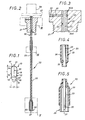
- the invention relates to a pressure tank 10 of the kind comprising, in an envelope 11, made in practice of rigid material, a separator 12 which divides the internal volume of said envelope 11 into two chambers of variable volume, namely a liquid chamber 13 and a gas chamber 14, said casing 11 itself comprising, at a distance from each other, two orifices, not detailed in these figures, at namely a liquid orifice and a gas orifice, and said liquid chamber 13 and said gas chamber 14 each being respectively in communication with said orifices.
- the casing 11 is generally elongated, and it thus forms, over at least a portion of its length, in practice in its middle part, a cylinder 15 of diameter D, while its ends 16, 17 each form a hemisphere respectively.
- the separator 12 is a bladder, and in practice a bladder of flexible material, which is also elongated, like the envelope 11 , and whose opening, commonly called mouth, surrounds the gas orifice of the latter.
- this bladder forms, at the other end of it, what is agreed here to be called a transverse wall 18, this transverse wall 18, which is in fact generally in the shape of a hemisphere , extending generally transversely to the envelope 11.
- the transverse wall 18 of the separator 12 is generally movably mounted in this casing 11, due to the movements of contraction or expansion what is likely to be known therein the bladder constituting in this case this separator 12.
- a sensor 20 is used in the pressure tank 10 thus formed, which is a sensor sensitive to the presence of liquid, and which, thanks to an orifice of the envelope 11 in communication with the gas chamber 14, extends in said gas chamber 14.
- this sensor 20 is carried by a tubular plug 21 controlling the orifice of the envelope 11 through which it extends.
- this orifice is, very simply, the gas orifice of the envelope 11.
- tubular plug 21 is, in the embodiment shown, a threaded plug with a conical thread, which thereby ensures all the desired tightness.
- the sensitive end 22 of the sensor 20 which forms, in practice, the free end, is closer of said transverse wall 18 than of the orifice of the casing 11 through which it extends into the gas chamber 14, or, in other words, of the tubular plug 21 controlling this orifice.
- the senor 20 is preferably, according to the invention, an optical probe.
- Such an optical probe is well known in itself.
- optical conduit 23 which forms its essential constituent, and which is itself formed of at least one optical fiber.
- this sensitive end 22 is slightly tapered, before ending with a rounded end.
- the other end of the optical conduit 23 is intended to be in connection with a signal processing device 25, as shown diagrammatically in FIG. 6.
- the corresponding link 26 can be provided by the optical conduit 23 itself, the latter duly extending out of the envelope 11 for this purpose.
- connection 26 can be provided by an electrical conductor.
- a direct connection, via its optical conduit 23, of the sensor 20 with the signal processing device 25, has the advantage of being much more reliable and of being insensitive to interference, which can make it necessary in the case where the pressure tank 10 concerned is located in an environment which is not compatible with such a signal processing device 25, and, for example, in a humid, aggressive and / or explosive environment, this processing device of signals 25 then advantageously being in a room remote from that in which the pressure tank 10 is itself located.
- connection 26 can equally be provided by an optical conduit separate from the optical conduit 23 of the probe forming the sensor 20, and, in this case, the connector 28 is simply a connector suitable for ensuring a connection between two conduits optical.
- the optical conduit 23 has a very reduced diameter, less often than 1 mm, or even 0.5 mm.
- the optical probe forming according to the invention the sensor 20 is capable, by simple gravity, of taking the arrow.
- this optical probe is reduced in practice to a section of optical conduit 23, which, apart from such a possible deflection, is substantially rectilinear.
- the length L of this section of optical conduit 23, and therefore of the optical probe forming the sensor 20, counted from the tubular plug 21 carrying the latter, is preferably greater than 1.5 times the diameter D of the cylinder. 15 which the envelope 11 of the pressure tank 10 forms in its middle part.
- the optical probe forming the sensor 20 remains substantially rectilinear, suspended from it is, in a way, to the tubular plug 21 from which it extends.
- this optical probe which then extends in a cantilever fashion in the gas chamber 14, effectively takes , by gravity, of the arrow.
- the optical conduit 23 of the optical probe forming the sensor 20 is surrounded by a tubular guide 30 which itself extends in overhang from said tubular plug 21.
- This tubular guide 30, which is in fact formed by a capillary tube, can for example be made of metal.
- the optical probe forming the sensor 20 in order to impart progressive flexibility, upon its entry into the gas chamber 14, to the optical probe forming the sensor 20, it can advantageously be itself made of flexible material, and for example of elastomer.
- the optical conduit 23 is itself preferably secured by gluing to the tubular guide 30 which thus accompanies it over a portion of its length.
- This bonding can for example be carried out in the following manner: in the tubular plug 21, there is provided, transversely, a bore 32, which intersects the bore 31, by dividing the tubular guide 30 into two distinct sections 30A, 30B, and which is used for the injection, under pressure, of glue into the gap between the optical conduit 23 and both of said sections 30A, 30B of the tubular guide 30, this transverse bore 32 then being closed by a plug 33.
- the tubular guide 30 preferably has, and as shown, at its free end, at the internal periphery of its outlet, a chamfer 35, which, cutting down its corresponding edge obliquely, allows to spare the optical conduit 23 during any deflections of the latter relative to this tubular guide 30.
- the sensitive end 22 of the sensor 20 is surrounded by a tubular cage 36, being disposed radially at a distance from the side wall of the latter and axially set back relative to its outlet.
- this tubular cage 36 is a rigid and fixed cage.
- This tubular cage 36 has a sufficient diameter for a meniscus of liquid to be able to be established between it and the sensitive end 22 of the optical conduit 23.
- the tubular cage 36 has, axially, at least one slot 37 from its outlet.
- two such slots 37 can be provided, being arranged in diametrically opposite positions relative to each other.
- the optical conduit 23 of the optical probe forming according to the invention is, for its protection, as well as for a reduction in its deformation capacity elastic, jacketed by a sheath 39.
- this sheath 39 extends at least from the tubular guide 30, and at least as far as the tubular cage 36.
- this is a sheath made of synthetic material, and, for example, an elastomer sheath.
- pressure tanks 10 can be connected to the same signal processing device 25, which, on receipt of a signal indicative of a fault for one from them, makes it possible to identify which of these pressure tanks 10 is thus in default.
- the optical probe forming the sensor 20 is put in place on the pressure tank 10 to be fitted, according to the invention, by means of an adapter body 40 shown in isolation in FIGS. 8 and 9.
- this adapter body 40 has, on the one hand, projecting, at its lower part, a tubular plug 21 ⁇ , by which, as described in more detail below, it is adapted to be attached to the pressure tank 10 to be fitted, and, on the other hand, in the hollow, at its upper part, a tapped hole 42, by which it is adapted to receive the tubular plug 21 carrying the sensor 20 to be put in place.
- this tapped hole 42 is therefore conical, like the tubular plug 21.
- tubular plug 21 ⁇ which, like the tubular plug 21, is threaded, is cylindrical.
- the diameter of the axial channel 41 is made sufficient to allow the passage of the optical probe forming the sensor 20.
- the adapter body 40 has a transverse channel 43, which is in communication with its axial channel 41, and by which, as will appear below, it is adapted to receive a valve, not shown, this transverse channel forming , for this purpose, at its free end, a tapped hole 44.
- tubular plug 21 ⁇ is complementary to this threaded bore 44.
- the adapter body 40 has, transversely, in the embodiment shown, three channels, all of which are in communication with its axial channel 41, and which all form a threaded bore at their free end, namely, in addition the transverse channel 43 above, which is intended to allow the introduction of gas into the gas chamber 14 of the pressure tank 10 concerned, a transverse channel 45, which is intended for example to allow the implantation of a pressure sensor , not shown, and a transverse channel 46, which is intended for example to allow the installation of a temperature sensor, also not shown, these pressure and temperature sensors being intended to allow to have additional information on the proper functioning of such a pressure tank 10.
- the adapter body 40 according to the invention is presented, at the in the form of a nut, in the form of a cylindrical block of polygonal cross section, and in practice hexagonal, which facilitates the control in rotation proper to allow the screwing or unscrewing, and which therefore facilitates the setting in place on the pressure tank 10 to be fitted.
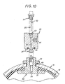
- FIG. 10 The implementation of such an adapter body is illustrated by FIG. 10, on which the casing 11 of such a pressure tank 10 is partially represented, with its gas orifice 48, and the bladder forming the separator 12 qu 'it contains.
- valve body 50 is installed in the gas orifice 48, and this valve body 50, which, inside the envelope 11, is surrounded by the opening 51 of the bladder forming the separator 12 ensures the sealing of this bladder in this envelope 11, while itself being secured by a nut 52 to this envelope 11 outside of the latter.
- valve body 50 has axially a channel 54, and, at the end thereof, on the side external to the casing 11, a threaded bore 55 suitable for the implantation of a valve (not shown), for controlling the inflation of the bladder forming the separator 12.
- the tubular plug 21 ⁇ of the adapter body 40 has the dimensions of the tapped hole 55, which are usually standard, and it is thus adapted to replace the valve normally implanted in this tapped hole 55, the latter then finding in return its place in its own tapped hole 44.
- the senor 20 implemented according to the invention can advantageously, if desired, equip a pre-existing pressure tank 10.
- a seal 57 for sealing cooperation with the corresponding upper face of the valve body 50.
- the overhang in the gas chamber 14 of the sensor 20 therefore extends only from this valve body 50, even if, theoretically, it extends from the plug. tubular 21 carrying this sensor 20.
- the tubular cage 36 is formed of arms 58 mounted to move between a retracted position, FIG. 11, for which they extend substantially parallel to the sensitive end 22 of the sensor 20, around it, and a deployed position, FIG. 12, for which their free end is spaced from this sensitive end 22, and the cage 36 thus formed of such movable arms 58 is surrounded by a tube 59 which, mounted axially movable, from outside the pressure tank 10 concerned, is capable of holding said arms 58 in the deployed position when it is itself in the advanced position, FIG. 11, and in releasing them, when it is in the retracted position, figure 12.
- the distance separating the sensitive end 22 of the sensor 20 from the free end of the arms 58 once they have thus been deployed is then greater, which is particularly suitable in the case where the liquid present in the liquid chamber 13 is relatively viscous, because he it is then relatively easier for this liquid to reach this sensitive end 22.
- the separator 12 can usually consist of a piston mounted movable transversely in the case 11.
- This piston forms alo by itself the transverse wall 18 of such a separator 12, this separator 12 reducing in this case to this transverse wall 18.
- the optical probe used for constituting the sensor 20 then forms at least one helical turn 60, and, in the vicinity of its sensitive end 22, it is preferably coupled, by fixing means 61, to the piston then forming the wall transverse 18.
- this optical probe in practice comprises several helical turns 60.
- the fastening means 61 by which it is coupled to the piston forming the transverse wall 18 are rotary means, to take account of any rotation, around the axis of the assembly, of this piston in the envelope 11.
- the sheath lining the optical fiber of the optical probe preferably used as sensor can, if desired, be molded onto the assembly, rather than being made of retractable material.
- the senor used is preferably an optical probe, it would not go beyond the scope of the invention either to replace it with another type of sensor.
- the orifice of the envelope of the pressure tank through which this sensor extends into the gas chamber thereof is not necessarily the gas orifice of this envelope.
- the sensor overhang in the gas chamber is made from this tubular plug.
- the envelope of the pressure tanks likely to be concerned is not necessarily cylindrical or elongated.
Landscapes
- Engineering & Computer Science (AREA)
- Physics & Mathematics (AREA)
- Fluid Mechanics (AREA)
- Mechanical Engineering (AREA)
- General Engineering & Computer Science (AREA)
- Measuring Fluid Pressure (AREA)
- Supply Devices, Intensifiers, Converters, And Telemotors (AREA)
- Filling Or Discharging Of Gas Storage Vessels (AREA)
Applications Claiming Priority (2)
| Application Number | Priority Date | Filing Date | Title |
|---|---|---|---|
| FR8612843 | 1986-09-15 | ||
| FR8612843A FR2603954B1 (fr) | 1986-09-15 | 1986-09-15 | Reservoir de pression a capteur de presence de liquide dans une chambre de gaz |
Publications (2)
| Publication Number | Publication Date |
|---|---|
| EP0261021A1 true EP0261021A1 (de) | 1988-03-23 |
| EP0261021B1 EP0261021B1 (de) | 1989-12-27 |
Family
ID=9338929
Family Applications (1)
| Application Number | Title | Priority Date | Filing Date |
|---|---|---|---|
| EP87402010A Expired EP0261021B1 (de) | 1986-09-15 | 1987-09-09 | Druckmittelbehälter mit Anwesenheitsgeber für Flüssigkeit in einer Gaskammer |
Country Status (5)
| Country | Link |
|---|---|
| US (1) | US4788851A (de) |
| EP (1) | EP0261021B1 (de) |
| JP (1) | JPS6377000A (de) |
| DE (1) | DE3761258D1 (de) |
| FR (1) | FR2603954B1 (de) |
Families Citing this family (27)
| Publication number | Priority date | Publication date | Assignee | Title |
|---|---|---|---|---|
| JPH0792083B2 (ja) * | 1988-03-04 | 1995-10-09 | 宣行 杉村 | 可動式椀状センサ付プラダ形アキユムレータ |
| US6232789B1 (en) | 1997-05-28 | 2001-05-15 | Cascade Microtech, Inc. | Probe holder for low current measurements |
| US5821462A (en) * | 1995-11-20 | 1998-10-13 | Corcom, Inc. | Insulated terminal and method of constructing same |
| DE10143173A1 (de) | 2000-12-04 | 2002-06-06 | Cascade Microtech Inc | Wafersonde |
| US6970634B2 (en) | 2001-05-04 | 2005-11-29 | Cascade Microtech, Inc. | Fiber optic wafer probe |
| US7040142B2 (en) * | 2002-01-04 | 2006-05-09 | Nxstage Medical, Inc. | Method and apparatus for leak detection in blood circuits combining external fluid detection and air infiltration detection |
| EP1509776A4 (de) | 2002-05-23 | 2010-08-18 | Cascade Microtech Inc | Sonde zum testen einer zu testenden einrichtung |
| US6724205B1 (en) | 2002-11-13 | 2004-04-20 | Cascade Microtech, Inc. | Probe for combined signals |
| US7057404B2 (en) | 2003-05-23 | 2006-06-06 | Sharp Laboratories Of America, Inc. | Shielded probe for testing a device under test |
| WO2005065258A2 (en) | 2003-12-24 | 2005-07-21 | Cascade Microtech, Inc. | Active wafer probe |
| KR20070058522A (ko) | 2004-09-13 | 2007-06-08 | 캐스케이드 마이크로테크 인코포레이티드 | 양측 프루빙 구조 |
| US7656172B2 (en) | 2005-01-31 | 2010-02-02 | Cascade Microtech, Inc. | System for testing semiconductors |
| US7535247B2 (en) | 2005-01-31 | 2009-05-19 | Cascade Microtech, Inc. | Interface for testing semiconductors |
| US7449899B2 (en) | 2005-06-08 | 2008-11-11 | Cascade Microtech, Inc. | Probe for high frequency signals |
| EP1932003A2 (de) | 2005-06-13 | 2008-06-18 | Cascade Microtech, Inc. | Breitbandige aktiv-passiv-differenzsignalsonde |
| DE102006001623B4 (de) * | 2006-01-11 | 2009-05-07 | Sartorius Stedim Biotech Gmbh | Behälter und Verfahren zum Mischen von Medien |
| US7609077B2 (en) | 2006-06-09 | 2009-10-27 | Cascade Microtech, Inc. | Differential signal probe with integral balun |
| US7403028B2 (en) | 2006-06-12 | 2008-07-22 | Cascade Microtech, Inc. | Test structure and probe for differential signals |
| US7764072B2 (en) | 2006-06-12 | 2010-07-27 | Cascade Microtech, Inc. | Differential signal probing system |
| US7723999B2 (en) | 2006-06-12 | 2010-05-25 | Cascade Microtech, Inc. | Calibration structures for differential signal probing |
| US7443186B2 (en) | 2006-06-12 | 2008-10-28 | Cascade Microtech, Inc. | On-wafer test structures for differential signals |
| US7876114B2 (en) | 2007-08-08 | 2011-01-25 | Cascade Microtech, Inc. | Differential waveguide probe |
| DE102011105813A1 (de) | 2011-05-05 | 2012-11-08 | Hydac Technology Gmbh | Sensorvorrichtung zum Detektieren von strömungsfähigen Medien, eine Druckeinrichtung und ein Messverfahren |
| DE102011100532A1 (de) * | 2011-05-05 | 2012-11-08 | Hydac Technology Gmbh | Medientrennvorrichtung, insbesondere Hydrospeicher einschließlich zugehöriger Messeinrichtung und Messverfahren |
| WO2017023303A1 (en) | 2015-08-05 | 2017-02-09 | Stren Microlift Technology, Llc | Hydraulic pumping system for use with a subterranean well |
| US10167865B2 (en) | 2015-08-05 | 2019-01-01 | Weatherford Technology Holdings, Llc | Hydraulic pumping system with enhanced piston rod sealing |
| CN115575053B (zh) * | 2022-10-10 | 2025-04-15 | 中冶赛迪工程技术股份有限公司 | 一种用于皮囊式蓄能器的皮囊破损检测装置 |
Citations (2)
| Publication number | Priority date | Publication date | Assignee | Title |
|---|---|---|---|---|
| FR2130037A1 (de) * | 1971-03-25 | 1972-11-03 | Danel M F | |
| FR2531754A1 (fr) * | 1982-08-12 | 1984-02-17 | Vsi Corp | Reservoir de pression hydraulique, tel qu'accumulateur muni d'un dispositif detecteur de panne |
Family Cites Families (2)
| Publication number | Priority date | Publication date | Assignee | Title |
|---|---|---|---|---|
| US4038650A (en) * | 1975-10-14 | 1977-07-26 | Martin Evans | Fluid level detector and probe assembly |
| US4487226A (en) * | 1982-08-12 | 1984-12-11 | Vsi Corporation | Failure sensing hydraulic accumulator and system |
-
1986
- 1986-09-15 FR FR8612843A patent/FR2603954B1/fr not_active Expired
-
1987
- 1987-09-01 US US07/091,670 patent/US4788851A/en not_active Expired - Fee Related
- 1987-09-09 DE DE8787402010T patent/DE3761258D1/de not_active Expired - Lifetime
- 1987-09-09 EP EP87402010A patent/EP0261021B1/de not_active Expired
- 1987-09-16 JP JP62231988A patent/JPS6377000A/ja active Pending
Patent Citations (2)
| Publication number | Priority date | Publication date | Assignee | Title |
|---|---|---|---|---|
| FR2130037A1 (de) * | 1971-03-25 | 1972-11-03 | Danel M F | |
| FR2531754A1 (fr) * | 1982-08-12 | 1984-02-17 | Vsi Corp | Reservoir de pression hydraulique, tel qu'accumulateur muni d'un dispositif detecteur de panne |
Also Published As
| Publication number | Publication date |
|---|---|
| FR2603954B1 (fr) | 1988-12-16 |
| DE3761258D1 (de) | 1990-02-01 |
| JPS6377000A (ja) | 1988-04-07 |
| FR2603954A1 (fr) | 1988-03-18 |
| US4788851A (en) | 1988-12-06 |
| EP0261021B1 (de) | 1989-12-27 |
Similar Documents
| Publication | Publication Date | Title |
|---|---|---|
| EP0261021B1 (de) | Druckmittelbehälter mit Anwesenheitsgeber für Flüssigkeit in einer Gaskammer | |
| EP0038492B1 (de) | Leckkontrollvorrichtung für gekapselte Hochspannungsanlage | |
| EP0134734B1 (de) | Verfahren und Vorrichtung zum Messen in einer Erdölbohrung | |
| EP0216706B1 (de) | Verfahren und Vorrichtung zur Messung des Brodelpunktes von Petroleum in einer unterirdischen Schicht | |
| FR2633718A1 (fr) | Cellule d'essais triaxiaux de contraintes sur un echantillon de roche et methode d'essais utilisant une telle cellule | |
| EP0148696A1 (de) | Vorrichtung und Verfahren zur Entnahme einer repräsentativen Probe der Flüssigkeit in einem Bohrloch | |
| EP0122839A1 (de) | Verfahren und Vorrichtung zum Messen und/oder Ausführen von Arbeiten in einem Bohrloch | |
| FR2767556A1 (fr) | Outil de mesures en cours de forage destine a etre installe dans un train de tiges de forage et generateur d'impulsions pour un tel outil | |
| EP0337842B1 (de) | Verfahren und Vorrichtung zum Messen der Elastizität einer oberflächlichen Schicht, insbesondere der Haut | |
| FR2531754A1 (fr) | Reservoir de pression hydraulique, tel qu'accumulateur muni d'un dispositif detecteur de panne | |
| CH427666A (fr) | Appareil d'essai du comportement mécanique statique du sol ou d'autres matériaux à partir d'un forage | |
| FR2638526A1 (fr) | Procede et appareil pour detecter des fissures dans des pales de rotor d'helicoptere | |
| FR2606008A1 (fr) | Tete de remplissage pour machine de remplissage de bouteilles et machine de remplissage equipee de telles tetes de remplissage | |
| FR2776135A1 (fr) | Conduit associe a un conducteur electrique de detection, par exemple pour le tirage ou poussage d'un cable | |
| FR2703157A1 (fr) | Dispositif pour la mesure de la porosité d'un élément de filtre. | |
| FR2795174A1 (fr) | Dispositif de controle de niveau de fluide dans le carter | |
| EP0964235A1 (de) | Leckdetector für Flüssigkeiten | |
| EP0419309A1 (de) | Vorrichtung zur Entnahme einer Fluidprobe aus einem Bohrloch | |
| EP0047707A1 (de) | Nachfüllverfahren für ein Wegwerfgasfeuerzeug ohne Docht und Feuerzeuge für die Durchführung dieses Verfahrens | |
| EP1166040B1 (de) | Bragg-gitter-dehnungsmesser und verfahren zur herstellung dieses dehnungsmessers | |
| EP0273801B1 (de) | Verschleissfühler für eine Abnutzungswarnvorrichtung für einen Reibbelag | |
| WO1996035937A1 (fr) | Systeme d'obturation d'un matras et appareil de traitement par micro-ondes comportant un tel systeme d'obturation | |
| FR2546969A1 (fr) | Dispositif de maintien du niveau d'un liquide de lubrification dans le carter d'un moteur a combustion interne | |
| FR2796151A1 (fr) | Procede et dispositif pour determiner la densite moyenne d'un fluide circulant dans un puits d'hydrocarbure incline ou horizontal | |
| FR2638153A1 (fr) | Dispositif de remplissage d'un reservoir de liquide comportant un orifice de trop-plein |
Legal Events
| Date | Code | Title | Description |
|---|---|---|---|
| PUAI | Public reference made under article 153(3) epc to a published international application that has entered the european phase |
Free format text: ORIGINAL CODE: 0009012 |
|
| AK | Designated contracting states |
Kind code of ref document: A1 Designated state(s): BE CH DE ES GB IT LI LU NL |
|
| 17P | Request for examination filed |
Effective date: 19880423 |
|
| 17Q | First examination report despatched |
Effective date: 19881201 |
|
| GRAA | (expected) grant |
Free format text: ORIGINAL CODE: 0009210 |
|
| AK | Designated contracting states |
Kind code of ref document: B1 Designated state(s): BE CH DE ES GB IT LI LU NL |
|
| REF | Corresponds to: |
Ref document number: 3761258 Country of ref document: DE Date of ref document: 19900201 |
|
| ITF | It: translation for a ep patent filed | ||
| GBT | Gb: translation of ep patent filed (gb section 77(6)(a)/1977) | ||
| PG25 | Lapsed in a contracting state [announced via postgrant information from national office to epo] |
Ref country code: ES Free format text: LAPSE BECAUSE OF FAILURE TO SUBMIT A TRANSLATION OF THE DESCRIPTION OR TO PAY THE FEE WITHIN THE PRESCRIBED TIME-LIMIT Effective date: 19900407 |
|
| PLBE | No opposition filed within time limit |
Free format text: ORIGINAL CODE: 0009261 |
|
| STAA | Information on the status of an ep patent application or granted ep patent |
Free format text: STATUS: NO OPPOSITION FILED WITHIN TIME LIMIT |
|
| 26N | No opposition filed | ||
| ITTA | It: last paid annual fee | ||
| PGFP | Annual fee paid to national office [announced via postgrant information from national office to epo] |
Ref country code: LU Payment date: 19920826 Year of fee payment: 6 |
|
| EPTA | Lu: last paid annual fee | ||
| PGFP | Annual fee paid to national office [announced via postgrant information from national office to epo] |
Ref country code: CH Payment date: 19930714 Year of fee payment: 7 |
|
| PGFP | Annual fee paid to national office [announced via postgrant information from national office to epo] |
Ref country code: BE Payment date: 19930715 Year of fee payment: 7 |
|
| PG25 | Lapsed in a contracting state [announced via postgrant information from national office to epo] |
Ref country code: LU Free format text: LAPSE BECAUSE OF NON-PAYMENT OF DUE FEES Effective date: 19930909 |
|
| PGFP | Annual fee paid to national office [announced via postgrant information from national office to epo] |
Ref country code: NL Payment date: 19930930 Year of fee payment: 7 |
|
| PGFP | Annual fee paid to national office [announced via postgrant information from national office to epo] |
Ref country code: DE Payment date: 19931129 Year of fee payment: 7 |
|
| PGFP | Annual fee paid to national office [announced via postgrant information from national office to epo] |
Ref country code: GB Payment date: 19940308 Year of fee payment: 7 |
|
| PG25 | Lapsed in a contracting state [announced via postgrant information from national office to epo] |
Ref country code: GB Effective date: 19940909 |
|
| PG25 | Lapsed in a contracting state [announced via postgrant information from national office to epo] |
Ref country code: LI Effective date: 19940930 Ref country code: CH Effective date: 19940930 Ref country code: BE Effective date: 19940930 |
|
| BERE | Be: lapsed |
Owner name: OLAER INDUSTRIES Effective date: 19940930 |
|
| PG25 | Lapsed in a contracting state [announced via postgrant information from national office to epo] |
Ref country code: NL Effective date: 19950401 |
|
| GBPC | Gb: european patent ceased through non-payment of renewal fee |
Effective date: 19940909 |
|
| NLV4 | Nl: lapsed or anulled due to non-payment of the annual fee | ||
| REG | Reference to a national code |
Ref country code: CH Ref legal event code: PL |
|
| PG25 | Lapsed in a contracting state [announced via postgrant information from national office to epo] |
Ref country code: DE Effective date: 19950601 |
|
| PG25 | Lapsed in a contracting state [announced via postgrant information from national office to epo] |
Ref country code: IT Free format text: LAPSE BECAUSE OF NON-PAYMENT OF DUE FEES Effective date: 20050909 |