EP0262931A2 - Planare Antenne - Google Patents
Planare Antenne Download PDFInfo
- Publication number
- EP0262931A2 EP0262931A2 EP87308629A EP87308629A EP0262931A2 EP 0262931 A2 EP0262931 A2 EP 0262931A2 EP 87308629 A EP87308629 A EP 87308629A EP 87308629 A EP87308629 A EP 87308629A EP 0262931 A2 EP0262931 A2 EP 0262931A2
- Authority
- EP
- European Patent Office
- Prior art keywords
- dielectric layer
- planar antenna
- methylbutene
- thickness
- dielectric
- Prior art date
- Legal status (The legal status is an assumption and is not a legal conclusion. Google has not performed a legal analysis and makes no representation as to the accuracy of the status listed.)
- Withdrawn
Links
Images
Classifications
-
- H—ELECTRICITY
- H01—ELECTRIC ELEMENTS
- H01Q—ANTENNAS, i.e. RADIO AERIALS
- H01Q21/00—Antenna arrays or systems
- H01Q21/0087—Apparatus or processes specially adapted for manufacturing antenna arrays
-
- H—ELECTRICITY
- H01—ELECTRIC ELEMENTS
- H01Q—ANTENNAS, i.e. RADIO AERIALS
- H01Q1/00—Details of, or arrangements associated with, antennas
- H01Q1/36—Structural form of radiating elements, e.g. cone, spiral, umbrella; Particular materials used therewith
- H01Q1/38—Structural form of radiating elements, e.g. cone, spiral, umbrella; Particular materials used therewith formed by a conductive layer on an insulating support
-
- Y—GENERAL TAGGING OF NEW TECHNOLOGICAL DEVELOPMENTS; GENERAL TAGGING OF CROSS-SECTIONAL TECHNOLOGIES SPANNING OVER SEVERAL SECTIONS OF THE IPC; TECHNICAL SUBJECTS COVERED BY FORMER USPC CROSS-REFERENCE ART COLLECTIONS [XRACs] AND DIGESTS
- Y10—TECHNICAL SUBJECTS COVERED BY FORMER USPC
- Y10S—TECHNICAL SUBJECTS COVERED BY FORMER USPC CROSS-REFERENCE ART COLLECTIONS [XRACs] AND DIGESTS
- Y10S428/00—Stock material or miscellaneous articles
- Y10S428/901—Printed circuit
Definitions
- the present invention relates to a planar antenna.
- planar antenna has been developed for receiving satellite broadcasting waves. It has the merit of being little influenced by snow, wind pressure, etc. as compared to a parabolic antenna. However, at present, the problem with planar antennae is that there is little gain.
- Connectors, printed circuit boards, metal-plated plastics used for magnetic recording materials and durable composite materials such as packaging material and bottles which contain 3-methylbutene-1.
- the present inventors have found that the high-frequency characteristics which have not been obtained by the conventional dielectric substrate for the planar antenna can be obtained by the use of a resin composed of a homopolymer of 3-methylbutene-1 or a copolymer of 3-methylbutene-1 and an alpha-olefin of from 2 to 12 carbon atoms and/or a polyene as the dielectric layer, and based on the finding, the present invention have been attained.
- a planar antenna comprising a dielectric layer containing a homopolymer of 3-methylbutene-1 or a copolymer of 3-methylbutene-1 and an alpha-olefin of from 2 to 12 carbon atoms, a polyene or a mixture thereof, a conductor laminated on the whole back surface of the dielectric layer and a circularly polarized radiation microstrip element formed from a metal foil and provided on the other surface of the dielectric layer.
- a method for producing a planar antenna comprises the steps of interposing a dielectric layer containing a homopolymer of 3-methylbutene-1 or a copolymer of 3-methylbutene-1 and an alpha-olefin of from 2 to 12 carbon atoms, a polyene or a mixture thereof between a conductor and a metal foil, molding the thus formed laminate by thermal pressing at a temperature of from 280 to 330 °C under a pressure of from 40 to 50 kg/cm2, and etching the metal foil on the surface of the dielectric substrate, thereby forming a microstrip element circuit.
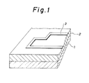
- Fig. 1 shows an example of the planar antenna according to the present invention.
- the heart of the present invention lies in the use of a dielectric layer containing a homopolymer of 3-methylbutene-1 or a copolymer of 3-methylbutene-1 and an alpha-olefin of from 2 to 12 carbon atoms and/or a polyene as a dielectric layer in a planar antenna comprising the dielectric layer, a conductor laminated on the whole back surface of the dielectric layer and a circularly polarized radiation microstrip element formed from a metal foil and provided on the surface of the dielectric layer.
- the dielectric layer containing a homopolymer of 3-methylbutene-1 or a copolymer of 3-methylbutene-1 and an alpha-olefin of from 2 to 12 carbon atoms and/or a polyene which is used in the present invention, a single or laminated substance comprising film or sheet of the polymer or copolymer of a thickness of from 20 to 1000 ⁇ m may be used.
- the thickness of the dielectric layer is in the extent of from 500 to 1000 ⁇ m. In the case where the thickness is below 500 ⁇ m, the gain becomes smaller and on the other hand, in the case where the thickness is over 1000 ⁇ m, the effective area of the antenna becomes smaller. Namely, these two cases are unfavorable.
- the particularly preferable thickness of the dielectric layer is in the extent of from 750 to 850 ⁇ m.
- the dielectric layer includes a copolymer of 3-methylbutene-1 of not less than 70% by weight, preferably not less than 80 % by weight and an alpha-olefin of from 2 to 12 carbon atoms and/or a polyene of not more than 30% by weight, preferably not more than 20 % by weight from the viewpoint of the moldability of the material.
- the homopolymer of 3-methylbutene-1 shows a melting point of from 260 to 310°C, a dielectric constant ( ⁇ ) of from 2.0 to 2.2 and a dielectric loss tangent (tan ⁇ ) of from 10 ⁇ 10 ⁇ 4 to 12 ⁇ 10 ⁇ 4 at a frequency of 12 GHz, namely the homopolymer of 3-methylbutene-1 is provided with excellent properties as the dielectric substance for the planar antenna.
- a glass cloth of from 50 to 200 ⁇ m in thickness between the dielectric layer and the metal foil.
- a dielectric constant ( ⁇ ) and a dielectric loss tangent (tan ⁇ )of the thus laminated material are respectively not larger than 2.2 and not larger than 15 ⁇ 10 ⁇ 4.
- those made of alkali glass and those made of quartz glass may be exemplified, and from the viewpoint of electrical properties, those made of quartz glass are preferable.
- the dielectric constant ( ⁇ ) becomes to not higher than 2.0, preferably not higher than 1.7 and the dielectric loss tangent (tan ⁇ ) becomes to not higher than 7 ⁇ 10 ⁇ 4, preferably not higher than 5 ⁇ 10 ⁇ 4.
- the specific properties of higher degree can be achieved, and it is particularly favorable.
- a copper-damage inhibitor, an anti-ultraviolet agent, an antioxidant, etc. may be added into the dielectric layer if necessary.
- a filler such as glass balloon, alumina fiber, alumina cloth, silica, mica, etc. may be added into the dielectric layer in the extent which does not damage the dielectric properties of the dielectric layer.
- Fig. 1 shows an example of the planar antenna according to the present invention
- 1 is a conductor
- 2 is a dielectric layer of a polymer of 3-methylbutene-1
- 3 is a microstrip element.
- the conductor 1 is composed of a metal plate of aluminum, etc. and generally has a thickness of from 0.5 to 3.0 mm.
- the microstrip element (receiving circuit) 3 is generally formed by etching a metal foil of copper, etc. of from 10 to 40 ⁇ m in thickness.
- the pattern of the circuit is designed for receiving the circularly polarized waves sent from the broadcasting satellite and in consideration of the receiving frequency band, etc.
- the electric current generated by receiving the electric-wave flows in the microstrip element 3 and is sent to converter and tuner through the coaxial cable via the feed point (not shown in Fig. 1).
- the dielectric substrate for the planar antenna which has the above-mentioned construction, is produced as follows.
- a sheet of the polymer of 3-methylbutene-1 of a thickness of from 500 to 1000 ⁇ m is interposed, and the thus formed laminate are molded into one body by an electrically heating press of a temperature of heat plate of from 280 to 330 °C and of a pressure of from 10 to 50 g/cm2, thereby obtaining a dielectric substrate having the two metal-clad surfaces for the planar antenna.
- the copper foil the electrolytic copper foil, the rolled copper foil and the oxygen-free copper foil can be used, however, from the viewpoint of the high frequency properties, the oxygen-free copper foil is preferable.
- the dielectric substance in order to provide the strength and the durability, it is possible to laminate the afore-mentioned glass cloth, a film of fluorocarbon resin (Teflon®, etc.), a composite material of a fluorocarbon resin and glass cloth, etc. in combination with the film or sheet of a polymer of 3-methylbutene-1 and to mold the thus formed laminate into one body by heating under a pressure.
- a film of fluorocarbon resin Teflon®, etc.
- a composite material of a fluorocarbon resin and glass cloth etc.
- the polymer of 3-methylbutene-1 is a modified polymer obtained by graft-polymerizing a radically polymerizable monomer to at least part of the polymer of 3-methylbutene-1.
- various monomers such as an unsaturated carboxylic acid and the derivative thereof, for instance, a monocarboxylic acid such as acrylic acid, an ester derivative such as glycidyl acrylate, an unsaturated dicarboxylic acid and the anhydride thereof such as maleic acid and maleic anhydride, an amide such as maleamide, unsaturated carboxylic acids such as cycloaliphatic polyvalent carboxylic acids containing unsaturated bonds, an aromatic vinyl compound such as styrene and alpha-methylstyrene, a vinyl ester such as vinyl acetate, etc. may be used. It is possible to carry out the modification of the polymer of 3-methylbutene-1 by the use of a mixture of the above-mentioned monomers.
- an unsaturated carboxylic acid and the derivative thereof such as an unsaturated monocarboxylic acid, an ester derivative, an unsaturated dicarboxylic acid and the anhydride thereof is preferable.
- the most preferable is an unsaturated dicarboxylic acid and the anhydride thereof.
- the amount of graft polymerization may be generally in the extent of from 0.01 to 10% by weight per the grafted polymer of 3-methylbutene-1, however, according to circumstances, the grafted polymer having graft polymerization of upto 60% by weight may be used.
- the amount of the unsaturated carboxylic acid is in the extent of from 0.02 to 1% by weight per the finally obtained composition.
- the surface of the film or sheet of the polymer of 3-methylbutene-1 and fluorocarbon resin has been treated with corona discharge, etc.
- the polymer of 3-methylbutene-1 porous In order to further improve the gain, it is preferable to make the polymer of 3-methylbutene-1 porous, and the extent of porosity is generally not smaller than 1.2 times, preferably from 1.5 to 5 times as calculated by expansion ratio.
- the method of compounding a plasticizer with the polymer and extracting the thus compounded plasticizer is a preferable method.
- plasticizer which is compounded with the polymer of 3-methylbutene-1 [Component (A)]
- an aliphatic compound, an aromatic compound, an aliphatic mineral oil and an aromatic mineral oil is preferably used according to the under-mentioned reasons.
- the compatibility thereof with the substrative resin is favorable; (s) they are soluble in a easily handlable solvent such as a lower alcohol, a hydrocarbon or a mixture thereof and (3) they are excellent in thermal stability and the boiling point thereof is not lower than 260°C.
- Alcohols such as cetyl alcohol[CH3(CH2)14CH2OH], heptadecyl alcohol[CH3(CH2)15CH2OH], stearyl alcohol[CH3(CH2)16CH2OH], ceryl alcohol[CH3(CH2)24CH2OH] and behenyl alcohol[CH3(CH2)20CH2OH]; ethers such as dioctyl ether[(C8H17)2O], didecyl ether[(C10H21)2O], didodecyl ether[(C12H25)2O] and dioctadecyl ether[(C18H37)2O]; ketones such as methyl tetradecyl ketone[CH3CO(CH2)13CH3], n-propyl hexadecyl ketone[CH3(CH2)2CO(CH2)15CH3], didodecyl ketone
- a Component (B) In order to produce the porous sheet having minute and uniform pores, from 30 to 80 % by weight of a Component (B) are compounded with from 20 to 70 % by weight of a Component (A) and a film or sheet of a thickness or from 20 to 1000 ⁇ m is produced from the thus compounded materials by inflation molding, T-die sheet molding, press molding, etc. at a temperature of from 260 to 320°C.
- the plasticizer in the thus obtained sheet is removed from the sheet by extracting the plasticizer with a low-boiling solvent such as a lower alcohol (methanol, ethanol, propanol, etc.), a ketone(acetone, methyl ethyl ketone, etc.), a saturated aliphatic hydrocarbon(hexane, heptane, etc.) or a mixture thereof at a temperature of from 20 to 80°C.
- a low-boiling solvent such as a lower alcohol (methanol, ethanol, propanol, etc.), a ketone(acetone, methyl ethyl ketone, etc.), a saturated aliphatic hydrocarbon(hexane, heptane, etc.) or a mixture thereof at a temperature of from 20 to 80°C.
- a low-boiling solvent such as a lower alcohol (methanol, ethanol, propanol, etc.), a ketone(acetone, methyl
- the thus obtained porous sheet composed of the polymer of 3-methylbutene-1 is interposed between an aluminum plate of a thickness of from 0.5 to 3.0 mm and a copper foil of a thickness of from 10 to 40 ⁇ m, and the thus formed laminate is molded into a dielectric substrate having the two metal-clad surfaces for the planar antenna by an electrothermal press molding machine at a heat plate temperature of from 260 to 320°C under a pressure of 5 ⁇ 30 kg/cm2.
- dry film is laminated on a surface of the copper foil of the dielectric substrate and after exposing and developing, the circuit is formed by etching the copper foil with an aqueous solution of ferric chloride, thereby producing the planar antenna.
- the planar antenna according to the present invention has a dielectric constant ( ⁇ ) of not higher than 2.2, preferably not higher than 2.0, more preferably not higher than 1.7, a dielectric loss tangent (tan ⁇ ) of not higher than 15 ⁇ 10 ⁇ 4, preferably not higher than 7 ⁇ 10 ⁇ 4, more preferably not higher than 5 ⁇ 10 ⁇ 4 and a gain of not less than 30 dB, preferably not less than 31.5 dB.
- a planar antenna according to the present invention is excellent in high-frequency properties and thermal-resistance, and can be obtained at a low cost.
- planar antenna according to the present invention realizes a large contribution in the propagation thereof as a part of the receiving system of the satellite broadcasting in future.
- planar antenna according to the present invention will be explained in detail while referring to Examples and Comparative Examples as follows.
- the polymers A to D of 3-methylbutene-1 were used after improving the wettability thereof by treating thereof with corona discharge.
- An electrolytic copper foil of 35 ⁇ m in thickness, a film of the polymer A of 3-methylbutene-1 of 800 ⁇ m in thickness and an aluminum plate of 2.0 mm in thickness were laminated in this order, and the thus formed laminate were molded into one body by heating at a hot plate temperature of 300°C under a pressure of 40 kg/cm2.
- An oxygen-free copper foil of 35 ⁇ m in thickness, a film of the polymer B of 3-methylbutene-1 of 800 ⁇ m in thickness and an aluminum plate of 2.0 mm in thickness were laminated in this order, and the thus formed laminate were molded into one body by heating at a hot plate temperature of 300°C under a pressure of 40 kg/cm2.
- An oxygen-free copper foil of 35 ⁇ m in thickness, a film of Teflon® of 50 ⁇ m in thickness, a film of the polymer C of 3-methylbutene-1 of 800 ⁇ m in thickness and an aluminum plate of 2.0 mm in thickness were laminated in this order, and the thus formed laminate were molded into one body by heating at a hot plate temperature of 350°C under a pressure of 40 kg/cm2.
- An electrolytic copper foil of 35 ⁇ m in thickness, a film of Teflon® of 50 ⁇ m in thickness, a Teflon® ⁇ glass cloth prepreg of 200 ⁇ m in thickness, a film of the polymer D of 3-methylbutene-1 of 600 ⁇ m in thickness and an aluminum plate of 2.0 mm in thickness were laminated in this order, and the thus formed laminate were molded into one body by heating at a hot plate temperature of 350°C under a pressure of 40 kg/cm2.
- An oxygen-free copper foil of 35 ⁇ m in thickness, a film of the polymer A of 3-methylbutene-1 of 200 ⁇ m in thickness, a glass cloth of 100 ⁇ m in thickness, a film of the polymer A of 3-methylbutene-1 of 500 ⁇ m in thickness and an aluminum plate of 2.0 mm in thickness were laminated in this order, and the thus formed laminate were molded into one body by heating at a hot plate temperature of 300°C under a pressure of 40 kg/cm2.
- An oxygen-free copper foil of 35 ⁇ m in thickness, a film of the polymer A of 3-methylbutene-1 of 200 ⁇ m in thickness, a glass cloth of 100 ⁇ m in thickness, a film of the polymer A of 3-methylbutene-1 of 500 ⁇ m in thickness, an oxygen-free copper foil of 35 ⁇ m in thickness, an adhesive film of epoxy resins of 50 ⁇ m in thickness and an aluminum plate of 2.0 mm in thickness were laminated in this order, and the thus formed laminate were molded into one body by heating at a hot plate temperature of 300°C under a pressure of 40 kg/cm2.
- the thus obtained sheet was treated for 20 min in ethanol at from 50 to 60°C to extract AROMIX® from the sheet.
- a porous sheet of 800 ⁇ m in thickness was obtained.
- An oxygen-free copper foil of 35 ⁇ m in thickness, a film of the polymer B of 3-methylbutene-1 of 30 ⁇ m in thickness, the thus obtained porous sheet of the polymer B of 3-methylbutene-1 of 800 ⁇ m in thickness and an aluminum plate of 2.0 mm in thickness were laminated in this order, and the thus formed laminate were molded into one body at a hot plate temperature of 280°C under a pressure of 20 kg/cm2.
- An electrolytic copper foil of 35 ⁇ m in thickness, a sheet of cross-linked polyethylene of 800 ⁇ m in thickness and an aluminum plate of 2.0 mm in thickness were laminated in this order, and the thus formed laminate were molded into one body by heating thereof at a hot plate temperature of 350°C under a pressure of 40 kg/cm2.
- An electrolytic copper foil of 35 ⁇ m in thickness, a film of Teflon® of 50 ⁇ m in thickness, four pieces of Teflon® ⁇ glass cloth prepreg of each 200 ⁇ m in thickness, a film of Teflon® of 50 ⁇ m in thickness and an aluminum plate of 2.0 mm in thickness were laminated in this order, and the thus formed laminate were molded into one body by heating thereof at a hot plate temperature of 350°C under a pressure of 40 kg/cm2.
- the copper foil was subjected to etching for forming the strip line and the dielectric constant ( ⁇ ), the dielectric loss tangent (tan ⁇ ) and the gain were measured at a frequency of 12 GHz(12 ⁇ 109 Hz). The results of the measurement are shown in Tables 1 and 2.
- the planar antennas obtained in Examples 1 to 6 are low in the dielectric constant and the dielectric loss tangent as compared to the conventional planar antenna, and at the same time, are excellent in the dimensional stability and the heat-resistance, and they can be obtained at a low cost, therefore they are excellent as the planar antenna.
- the oxygen-free copper foil was better than the electrolytic copper foil by 1 dB.
- the gain of the planar antenna of Example 6 was higher by about 0.5 dB than that of the planar antenna of Example 5.
- Example 7 As a result of the comparison of Example 7 with Example 2, it was found that the planar antenna having the porous dielectric layer was excellent in the durability and the gain, and had a high performance.
Landscapes
- Engineering & Computer Science (AREA)
- Manufacturing & Machinery (AREA)
- Laminated Bodies (AREA)
- Waveguide Aerials (AREA)
- Organic Insulating Materials (AREA)
- Non-Insulated Conductors (AREA)
Applications Claiming Priority (2)
| Application Number | Priority Date | Filing Date | Title |
|---|---|---|---|
| JP233010/86 | 1986-09-30 | ||
| JP61233010A JPS6386320A (ja) | 1986-09-30 | 1986-09-30 | 平面アンテナ用両面金属張り誘電体基板 |
Publications (2)
| Publication Number | Publication Date |
|---|---|
| EP0262931A2 true EP0262931A2 (de) | 1988-04-06 |
| EP0262931A3 EP0262931A3 (de) | 1989-08-09 |
Family
ID=16948400
Family Applications (1)
| Application Number | Title | Priority Date | Filing Date |
|---|---|---|---|
| EP87308629A Withdrawn EP0262931A3 (de) | 1986-09-30 | 1987-09-29 | Planare Antenne |
Country Status (3)
| Country | Link |
|---|---|
| US (1) | US4963891A (de) |
| EP (1) | EP0262931A3 (de) |
| JP (1) | JPS6386320A (de) |
Cited By (2)
| Publication number | Priority date | Publication date | Assignee | Title |
|---|---|---|---|---|
| FR2651953A1 (fr) * | 1989-09-12 | 1991-03-15 | France Etat | Support metallise a base de polymethylpentene et procede de fabrication de ce support. |
| EP0651458A1 (de) * | 1993-10-28 | 1995-05-03 | France Telecom | Ebene Antenne und Verfahren zu ihrer Herstellung |
Families Citing this family (12)
| Publication number | Priority date | Publication date | Assignee | Title |
|---|---|---|---|---|
| ZA941671B (en) * | 1993-03-11 | 1994-10-12 | Csir | Attaching an electronic circuit to a substrate. |
| GB9417401D0 (en) * | 1994-08-30 | 1994-10-19 | Pilkington Plc | Patch antenna assembly |
| US5767808A (en) * | 1995-01-13 | 1998-06-16 | Minnesota Mining And Manufacturing Company | Microstrip patch antennas using very thin conductors |
| US5844523A (en) * | 1996-02-29 | 1998-12-01 | Minnesota Mining And Manufacturing Company | Electrical and electromagnetic apparatuses using laminated structures having thermoplastic elastomeric and conductive layers |
| US6501350B2 (en) | 2001-03-27 | 2002-12-31 | Electrolock, Inc. | Flat radiating cable |
| US20050079903A1 (en) * | 2002-04-18 | 2005-04-14 | Hirokazu Taketomi | Cell phone and built-in antenna thereof |
| US7215299B2 (en) * | 2004-10-12 | 2007-05-08 | Eaton Corporation | Antenna protected from dielectric breakdown and sensor or switchgear apparatus including the same |
| US8414962B2 (en) | 2005-10-28 | 2013-04-09 | The Penn State Research Foundation | Microcontact printed thin film capacitors |
| US20100071197A1 (en) * | 2008-09-22 | 2010-03-25 | Fridy Joseph M | Integral antennas in metal laminates |
| US11069978B2 (en) * | 2017-04-07 | 2021-07-20 | Skyworks Solutions, Inc. | Method of manufacturing a radio-frequency module with a conformal shield antenna |
| JP2024095447A (ja) * | 2022-12-28 | 2024-07-10 | 株式会社クラレ | ミリ波レドーム |
| KR20250131775A (ko) | 2022-12-28 | 2025-09-03 | 주식회사 쿠라레 | 절연 필름, 동장 적층판, 및 밀리미터파 안테나 |
Family Cites Families (11)
| Publication number | Priority date | Publication date | Assignee | Title |
|---|---|---|---|---|
| GB2131232B (en) * | 1982-09-27 | 1986-05-08 | Rogers Corp | Microstrip antenna and method of manufacture thereof |
| DE3482557D1 (de) * | 1983-11-30 | 1990-07-26 | Mitsubishi Chem Ind | 3-methylbuten-1-polymer, dessen zusammensetzung und giessform. |
| FR2557497B1 (fr) * | 1983-12-29 | 1986-07-11 | Demeure Loic | Support metallise a base de polypropylene et procede de fabrication de ce support |
| DE3582262D1 (de) * | 1984-01-23 | 1991-05-02 | Showa Denko Kk | Reflektor fuer zirkular polarisierte wellen. |
| CA1242796A (en) * | 1984-10-12 | 1988-10-04 | Yoshihiro Kitsuda | Microwave plane antenna |
| US4772496A (en) * | 1985-06-15 | 1988-09-20 | Showa Denko Kabushiki Kaisha | Molded product having printed circuit board |
| US4829309A (en) * | 1986-08-14 | 1989-05-09 | Matsushita Electric Works, Ltd. | Planar antenna |
| JPH028611A (ja) * | 1988-06-27 | 1990-01-12 | Mitsubishi Heavy Ind Ltd | 排気のダウンウオツシユ防止装置 |
| JPH044405A (ja) * | 1990-04-23 | 1992-01-08 | Mori Seiki Co Ltd | 数値制御装置 |
| JPH057403A (ja) * | 1991-06-26 | 1993-01-19 | Iseki & Co Ltd | トラクタのリフトアーム角センサ |
| JP2949612B2 (ja) * | 1995-06-19 | 1999-09-20 | 株式会社粋好 | 和装用草履 |
-
1986
- 1986-09-30 JP JP61233010A patent/JPS6386320A/ja active Pending
-
1987
- 1987-09-29 EP EP87308629A patent/EP0262931A3/de not_active Withdrawn
- 1987-09-29 US US07/332,890 patent/US4963891A/en not_active Expired - Fee Related
Cited By (4)
| Publication number | Priority date | Publication date | Assignee | Title |
|---|---|---|---|---|
| FR2651953A1 (fr) * | 1989-09-12 | 1991-03-15 | France Etat | Support metallise a base de polymethylpentene et procede de fabrication de ce support. |
| EP0418148A1 (de) * | 1989-09-12 | 1991-03-20 | France Telecom | Verfahren zur Herstellung eines metallisierten Trägers auf Basis von Polymethylpenten |
| EP0651458A1 (de) * | 1993-10-28 | 1995-05-03 | France Telecom | Ebene Antenne und Verfahren zu ihrer Herstellung |
| FR2711845A1 (fr) * | 1993-10-28 | 1995-05-05 | France Telecom | Antenne plane et procédé de réalisation d'une telle antenne. |
Also Published As
| Publication number | Publication date |
|---|---|
| US4963891A (en) | 1990-10-16 |
| EP0262931A3 (de) | 1989-08-09 |
| JPS6386320A (ja) | 1988-04-16 |
Similar Documents
| Publication | Publication Date | Title |
|---|---|---|
| EP0262931A2 (de) | Planare Antenne | |
| US4353954A (en) | Flexible printed circuit base board and method for producing the same | |
| EP0382312B1 (de) | Härtbare Polyphenylenether-Zusammensetzung und eine daraus herstellbare gehärtete Zusammensetzung | |
| EP0991082B1 (de) | Dielektrische verbundwerkstoffzusammensetzung, und film, substrat, elektronische teile und formteile davon | |
| JP2002528611A (ja) | ウレタン又はエステル残基含有のビニル末端のポリブタジエン類 | |
| EP0257657B1 (de) | Substrat für Hochfrequenzschaltung und Verfahren zur Herstellung desselben | |
| JP7507382B2 (ja) | 樹脂組成物、並びに、それを用いたプリプレグ、樹脂付きフィルム、樹脂付き金属箔、金属張積層板及び配線基板 | |
| JPH09291148A (ja) | 変成ポリフェニレンオキサイドの製法、この製法による変成ポリフェニレンオキサイドを用いたエポキシ樹脂組成物、この組成物を用いたプリプレグ、及びこのプリプレグを用いた積層板 | |
| EP0739915A2 (de) | Wärmehärtbare Harzzusammensetzungen, daraus hergestellte elektrische Laminate und Verfahren zu deren Herstellung | |
| CN109760398B (zh) | 一种高频覆铜板含氟树脂半固化片组合方式 | |
| CN109370497B (zh) | 一种生产高速覆铜板的胶水的制备方法及其产品 | |
| JP3339301B2 (ja) | エポキシ樹脂組成物、この樹脂組成物を用いたプリプレグ及びこのプリプレグを用いた積層板 | |
| JP3265984B2 (ja) | エポキシ樹脂組成物、この樹脂組成物を用いたプリプレグ、及びこのプリプレグを用いた積層板 | |
| EP0642412B1 (de) | Bedruckte schaltträger | |
| JPH07162111A (ja) | 複合誘電体基板 | |
| JP3261871B2 (ja) | 積層板用プリプレグの製造法および積層板の製造法 | |
| JPH01173695A (ja) | 高周波回路用積層板 | |
| JPS62157403A (ja) | 平面アンテナ用両面金属張り誘電体基板の製造方法 | |
| JPS6386313A (ja) | 平面アンテナ用基板 | |
| JP2002536518A (ja) | マイクロ波透過性熱硬化性樹脂組成物、それより得られる電気的積層体及びそれらの製造方法 | |
| JPS61287739A (ja) | 積層板 | |
| JPH01126344A (ja) | 積層板の製造方法 | |
| JP2002053646A (ja) | エポキシ樹脂組成物、プリプレグ、及び、絶縁基板 | |
| JPH0740628B2 (ja) | 高周波回路用基板 | |
| JPS63126120A (ja) | 平面アンテナ用基板 |
Legal Events
| Date | Code | Title | Description |
|---|---|---|---|
| PUAI | Public reference made under article 153(3) epc to a published international application that has entered the european phase |
Free format text: ORIGINAL CODE: 0009012 |
|
| AK | Designated contracting states |
Kind code of ref document: A2 Designated state(s): DE FR GB |
|
| RIN1 | Information on inventor provided before grant (corrected) |
Inventor name: AOYAGI, YOSHIKI Inventor name: MURAKAMI, ATSUSHI Inventor name: AJIKI, MITSUNORI Inventor name: SUZUKI, SHIGERU Inventor name: NAKADA, MAMORU |
|
| RAP1 | Party data changed (applicant data changed or rights of an application transferred) |
Owner name: MITSUBISHI KASEI CORPORATION Owner name: SUMITOMO BAKELITE COMPANY LIMITED |
|
| PUAL | Search report despatched |
Free format text: ORIGINAL CODE: 0009013 |
|
| RHK1 | Main classification (correction) |
Ipc: H01Q 1/38 |
|
| AK | Designated contracting states |
Kind code of ref document: A3 Designated state(s): DE FR GB |
|
| 17P | Request for examination filed |
Effective date: 19900120 |
|
| 17Q | First examination report despatched |
Effective date: 19920221 |
|
| STAA | Information on the status of an ep patent application or granted ep patent |
Free format text: STATUS: THE APPLICATION IS DEEMED TO BE WITHDRAWN |
|
| 18D | Application deemed to be withdrawn |
Effective date: 19920703 |