EP0262939A2 - Aerostatisches Lager - Google Patents
Aerostatisches Lager Download PDFInfo
- Publication number
- EP0262939A2 EP0262939A2 EP87308641A EP87308641A EP0262939A2 EP 0262939 A2 EP0262939 A2 EP 0262939A2 EP 87308641 A EP87308641 A EP 87308641A EP 87308641 A EP87308641 A EP 87308641A EP 0262939 A2 EP0262939 A2 EP 0262939A2
- Authority
- EP
- European Patent Office
- Prior art keywords
- porous graphite
- bearing
- gaseous fluid
- graphite member
- bearing assembly
- Prior art date
- Legal status (The legal status is an assumption and is not a legal conclusion. Google has not performed a legal analysis and makes no representation as to the accuracy of the status listed.)
- Granted
Links
Images

Classifications
-
- F—MECHANICAL ENGINEERING; LIGHTING; HEATING; WEAPONS; BLASTING
- F16—ENGINEERING ELEMENTS AND UNITS; GENERAL MEASURES FOR PRODUCING AND MAINTAINING EFFECTIVE FUNCTIONING OF MACHINES OR INSTALLATIONS; THERMAL INSULATION IN GENERAL
- F16C—SHAFTS; FLEXIBLE SHAFTS; ELEMENTS OR CRANKSHAFT MECHANISMS; ROTARY BODIES OTHER THAN GEARING ELEMENTS; BEARINGS
- F16C32/00—Bearings not otherwise provided for
- F16C32/06—Bearings not otherwise provided for with moving member supported by a fluid cushion formed, at least to a large extent, otherwise than by movement of the shaft, e.g. hydrostatic air-cushion bearings
- F16C32/0603—Bearings not otherwise provided for with moving member supported by a fluid cushion formed, at least to a large extent, otherwise than by movement of the shaft, e.g. hydrostatic air-cushion bearings supported by a gas cushion, e.g. an air cushion
- F16C32/0614—Bearings not otherwise provided for with moving member supported by a fluid cushion formed, at least to a large extent, otherwise than by movement of the shaft, e.g. hydrostatic air-cushion bearings supported by a gas cushion, e.g. an air cushion the gas being supplied under pressure, e.g. aerostatic bearings
- F16C32/0618—Bearings not otherwise provided for with moving member supported by a fluid cushion formed, at least to a large extent, otherwise than by movement of the shaft, e.g. hydrostatic air-cushion bearings supported by a gas cushion, e.g. an air cushion the gas being supplied under pressure, e.g. aerostatic bearings via porous material
-
- C—CHEMISTRY; METALLURGY
- C23—COATING METALLIC MATERIAL; COATING MATERIAL WITH METALLIC MATERIAL; CHEMICAL SURFACE TREATMENT; DIFFUSION TREATMENT OF METALLIC MATERIAL; COATING BY VACUUM EVAPORATION, BY SPUTTERING, BY ION IMPLANTATION OR BY CHEMICAL VAPOUR DEPOSITION, IN GENERAL; INHIBITING CORROSION OF METALLIC MATERIAL OR INCRUSTATION IN GENERAL
- C23C—COATING METALLIC MATERIAL; COATING MATERIAL WITH METALLIC MATERIAL; SURFACE TREATMENT OF METALLIC MATERIAL BY DIFFUSION INTO THE SURFACE, BY CHEMICAL CONVERSION OR SUBSTITUTION; COATING BY VACUUM EVAPORATION, BY SPUTTERING, BY ION IMPLANTATION OR BY CHEMICAL VAPOUR DEPOSITION, IN GENERAL
- C23C14/00—Coating by vacuum evaporation, by sputtering or by ion implantation of the coating forming material
- C23C14/22—Coating by vacuum evaporation, by sputtering or by ion implantation of the coating forming material characterised by the process of coating
- C23C14/24—Vacuum evaporation
- C23C14/32—Vacuum evaporation by explosion; by evaporation and subsequent ionisation of the vapours, e.g. ion-plating
-
- C—CHEMISTRY; METALLURGY
- C23—COATING METALLIC MATERIAL; COATING MATERIAL WITH METALLIC MATERIAL; CHEMICAL SURFACE TREATMENT; DIFFUSION TREATMENT OF METALLIC MATERIAL; COATING BY VACUUM EVAPORATION, BY SPUTTERING, BY ION IMPLANTATION OR BY CHEMICAL VAPOUR DEPOSITION, IN GENERAL; INHIBITING CORROSION OF METALLIC MATERIAL OR INCRUSTATION IN GENERAL
- C23C—COATING METALLIC MATERIAL; COATING MATERIAL WITH METALLIC MATERIAL; SURFACE TREATMENT OF METALLIC MATERIAL BY DIFFUSION INTO THE SURFACE, BY CHEMICAL CONVERSION OR SUBSTITUTION; COATING BY VACUUM EVAPORATION, BY SPUTTERING, BY ION IMPLANTATION OR BY CHEMICAL VAPOUR DEPOSITION, IN GENERAL
- C23C30/00—Coating with metallic material characterised only by the composition of the metallic material, i.e. not characterised by the coating process
-
- F—MECHANICAL ENGINEERING; LIGHTING; HEATING; WEAPONS; BLASTING
- F16—ENGINEERING ELEMENTS AND UNITS; GENERAL MEASURES FOR PRODUCING AND MAINTAINING EFFECTIVE FUNCTIONING OF MACHINES OR INSTALLATIONS; THERMAL INSULATION IN GENERAL
- F16C—SHAFTS; FLEXIBLE SHAFTS; ELEMENTS OR CRANKSHAFT MECHANISMS; ROTARY BODIES OTHER THAN GEARING ELEMENTS; BEARINGS
- F16C33/00—Parts of bearings; Special methods for making bearings or parts thereof
- F16C33/02—Parts of sliding-contact bearings
- F16C33/04—Brasses; Bushes; Linings
- F16C33/16—Sliding surface consisting mainly of graphite
-
- F—MECHANICAL ENGINEERING; LIGHTING; HEATING; WEAPONS; BLASTING
- F16—ENGINEERING ELEMENTS AND UNITS; GENERAL MEASURES FOR PRODUCING AND MAINTAINING EFFECTIVE FUNCTIONING OF MACHINES OR INSTALLATIONS; THERMAL INSULATION IN GENERAL
- F16C—SHAFTS; FLEXIBLE SHAFTS; ELEMENTS OR CRANKSHAFT MECHANISMS; ROTARY BODIES OTHER THAN GEARING ELEMENTS; BEARINGS
- F16C32/00—Bearings not otherwise provided for
- F16C32/06—Bearings not otherwise provided for with moving member supported by a fluid cushion formed, at least to a large extent, otherwise than by movement of the shaft, e.g. hydrostatic air-cushion bearings
- F16C32/0681—Construction or mounting aspects of hydrostatic bearings, for exclusively rotary movement, related to the direction of load
- F16C32/0685—Construction or mounting aspects of hydrostatic bearings, for exclusively rotary movement, related to the direction of load for radial load only
-
- F—MECHANICAL ENGINEERING; LIGHTING; HEATING; WEAPONS; BLASTING
- F16—ENGINEERING ELEMENTS AND UNITS; GENERAL MEASURES FOR PRODUCING AND MAINTAINING EFFECTIVE FUNCTIONING OF MACHINES OR INSTALLATIONS; THERMAL INSULATION IN GENERAL
- F16C—SHAFTS; FLEXIBLE SHAFTS; ELEMENTS OR CRANKSHAFT MECHANISMS; ROTARY BODIES OTHER THAN GEARING ELEMENTS; BEARINGS
- F16C32/00—Bearings not otherwise provided for
- F16C32/06—Bearings not otherwise provided for with moving member supported by a fluid cushion formed, at least to a large extent, otherwise than by movement of the shaft, e.g. hydrostatic air-cushion bearings
- F16C32/0681—Construction or mounting aspects of hydrostatic bearings, for exclusively rotary movement, related to the direction of load
- F16C32/0696—Construction or mounting aspects of hydrostatic bearings, for exclusively rotary movement, related to the direction of load for both radial and axial load
-
- F—MECHANICAL ENGINEERING; LIGHTING; HEATING; WEAPONS; BLASTING
- F16—ENGINEERING ELEMENTS AND UNITS; GENERAL MEASURES FOR PRODUCING AND MAINTAINING EFFECTIVE FUNCTIONING OF MACHINES OR INSTALLATIONS; THERMAL INSULATION IN GENERAL
- F16C—SHAFTS; FLEXIBLE SHAFTS; ELEMENTS OR CRANKSHAFT MECHANISMS; ROTARY BODIES OTHER THAN GEARING ELEMENTS; BEARINGS
- F16C33/00—Parts of bearings; Special methods for making bearings or parts thereof
- F16C33/02—Parts of sliding-contact bearings
- F16C33/04—Brasses; Bushes; Linings
- F16C33/043—Sliding surface consisting mainly of ceramics, cermets or hard carbon, e.g. diamond like carbon [DLC]
-
- Y—GENERAL TAGGING OF NEW TECHNOLOGICAL DEVELOPMENTS; GENERAL TAGGING OF CROSS-SECTIONAL TECHNOLOGIES SPANNING OVER SEVERAL SECTIONS OF THE IPC; TECHNICAL SUBJECTS COVERED BY FORMER USPC CROSS-REFERENCE ART COLLECTIONS [XRACs] AND DIGESTS
- Y10—TECHNICAL SUBJECTS COVERED BY FORMER USPC
- Y10S—TECHNICAL SUBJECTS COVERED BY FORMER USPC CROSS-REFERENCE ART COLLECTIONS [XRACs] AND DIGESTS
- Y10S384/00—Bearings
- Y10S384/90—Cooling or heating
- Y10S384/902—Porous member
Definitions
- This invention relates to improvements in a static pressure gas bearing assembly wherein a bearing member, called a bearing pad, made of a porous material is disposed at a bearing area opposed to a member (such as a rotatable shaft) to be supported and wherein a pressurized gaseous fluid such as pressurized air is discharged from pores of the bearing pad into a minute clearance between the bearing pad and the member to be supported such that a gaseous film is formed in this clearance to support the member to be supported.
- a bearing member called a bearing pad, made of a porous material
- porous graphite As for the material of the porous member usable as the bearing pad in the gas bearing assembly, usually, porous graphite is used.
- Such porous graphite member can be produced by: grinding calcined coke; kneading the ground coke with a binder such as pitch added thereto, while heating them; forming (by pressure molding) the kneaded coke powder into an article; heating the molded article to a temperature of about 1000 - 1400 °C for calcination; impregnating the calcined article with a binder pitch under reduced pressure so as to reduce interstices in the calcined article; heating again the article for calcination; and, after repeating the above-described impregnation and calcination, heating the article to a temperature of about 2000 - 3000 °C for graphitization.
- such conventional porous graphite material shows undesirable characteristics. For example, the density is low. Also, micro-cracking occurs easily. Further, the particle diameter of the coke powder is not uniform. Because of these features, when such porous graphite material is used as a bearing pad in a static pressure gas bearing assembly, the quantity of gaseous fluid discharged from the bearing surface (i.e., the rate of gas flow through the bearing pad) is too large or too small as compared with a designed value. Further, the quantity distribution is not uniform.
- the manufacture of conventional static pressure gas bearing assemblies using the porous graphite material as the bearing pad necessarily includes a flow adjustment operation which is to be excuted after the finishing of the bearing surface in order that a desired quantity of gaseous fluid is discharged with uniform distribution.
- the bearing surface of the porous graphite bearing pad is coated with or impregnated with resin or otherwise. Thereafter, while measuring the flow rate of gaseous fluid passed through the pad, the resin material or the like is removed gradually by use of a solvent until a uniform distribution of the discharging quantity of gaseous fluid is obtained.
- flow adjusting operation requires expert works by a skilled operator. As a result, it is difficult to retain the quality stably. Also, many processes are necessary. Due to these features, the necessity of the flow adjusting operation is a bar to the mass-production of the static pressure gas bearing assemblies.
- a static pressure gas bearing assembly wherein a pressurized gaseous fluid is discharged from pores of a porous graphite bearing member, having a bearing surface, into a minute clearance between the bearing surface and a member to be supported so as to form in this clearance a gaseous film effective to support the member to be supported and wherein the porous graphite bearing member is provided by an article having been formed by molding, calcining and graphitizing particles of a raw material usable as a carbon material and having particle diameters distributed substantially in a range not greater than 40 microns, the porous graphite bearing member thus having pores distributed substantially uniformly.
- the flow rate of the gaseous fluid at the bearing surface becomes inform with the result that the necessity of the flow adjusting operating which requires expert works of skilled operators, a long working time, many working steps, etc. and which increases the manufacturing cost can be omitted. Therefore, high-quality gas bearing assembly can always be manufactured with reduced cost.
- the porous graphite bearing member used in the present invention shows a very low swelling degree which is not greater than 0.02 %. Accordingly, in operation, it is not necessary to precisely control the ambient humidity.
- the porous graphite bearing member used in the present invention has high hardness. Because of such high hardness, where the bearing assembly of the present invention is used with a rotatable shaft member having a surface coating formed by hard chrome plating or otherwise, there is a possibility of undesirable seizing of the bearing member and the shaft member during rotation thereof if the bearing surface accidentally contacts the shaft member due to any drop of the gaseous fluid supplying pressure, any overloading or otherwise.
- the surface of the member to be supported by the bearing assembly and opposed to the bearing surface of the bearing member is coated with a film of titanium nitride, particularly suitably by ion plating process.
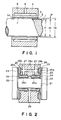
- the bearing assembly is used to support a member 1 which is a rotational shaft.
- the shaft 1 has a surface film 2 made of a titanium nitride material (TiN) and formed on the shaft 1 surface by ion plating.
- the bearing assembly includes a porous bearing member (bearing pad) 3 which is made of porous graphite according to the present invention.
- the porous graphite member 3 has been made by molding the raw material by cold isostatic press method, calcining the molded article and graphitizing the calcined article.
- the porous graphite bearing member has formed therein a number of pores which are distributed uniformly. Details of the porous graphite material used in the present embodiment will be described later.
- the bearing assembly further includes a housing 4, a gaseous fluid supplying port 5 and a gaseous fluid supplying chamber 6.
- the pressurized gaseous fluid When, in operation, the pressurized gaseous fluid is supplied from the fluid supplying port 5, the gaseous fluid flows into the fluid supplying chamber 6, and then, flows through the porous member 3, such that the gaseous fluid is discharged from the pores in the bearing surface 3a of the porous bearing member 3.
- a gaseous film is formed in a minute clearance between the shaft 1 and the bearing surface 3a.
- the gaseous fluid forming the gaseous film and thereby supporting the shaft 1 is exhausted outwardly of the bearing assembly.
- Table 1 shows the characteristics of the static pressure gas bearing assembly of the present embodiment, as compared with those of a convetional type static pressure gas bearing assembly.
- the flow rate of the gaseous fluid passed through the porous graphite material (bearing member), the thickness of the porous member and the gaseous fluid supplying pressure have been selected as the characteristics to be compared.
- a very long time of an order of about 8 hours is required to complete the flow adjsuting operation.
- a predetermined flow rate is obtainable without the flow adjustment to the porous graphite member.
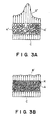
- Figure 3A is a schematic view showing a model of the distribution of the flow rate (quantity) of gaseous fluid at the bearing surface of a conventional type porous graphite bearing member used in a conventional type static pressure gas bearing assembly.
- Figure 3B is a schematic view showing a model of the distribution of the flow rate (quantity) of the gaseous fluid at the bearing surface of the porous graphite bearing member used in the static pressure gas bearing assembly according to the present embodiment.
- a reference character A ⁇ denotes the section of the porous graphite used as the conventional type bearing member; a reference character A denotes the section of the porous graphite used in the present embodiment as the bearing member; a reference character B ⁇ denotes the distribution of the flow rate of the gaseous fluid passed through the porous graphite member of the conventional bearing assembly; a reference character B denotes the distribution of the flow rate of the gaseous fluid passed through the porous graphite used in the present embodiment; and a reference character C denotes a constant gaseous fluid supplying pressure (g).
- the particles K ⁇ have non-uniform particle diameters and, in addition thereto, the pores are distributed non-uniformly. Therefore, the distribution B ⁇ of the flow rate of the gaseous fluid passed through the bearing pad is not uniform, as illustrated.
- the particles K have uniformly distributed particle diameters, the diameters being not more than about 40 microns. Particularly, approximately 80 % of the particles have diameters ranging from 1 - 20 microns, as will be described later.
- pores of the graphite material are distributed substantially uniformly. As a result, a substantially uniform distribution of the flow rate of the passing gaseous fluid is obtainble, as illustrated.
- porous graphite used in the present embodiment it can be produced by use of a raw material which are used in the production of such a porous graphite material that is commercially sold in the trade name "Ceraphite” by Toshiba Ceramics Kabushiki Kaisha, Japan).
- a raw material which are used in the production of such a porous graphite material that is commercially sold in the trade name "Ceraphite” by Toshiba Ceramics Kabushiki Kaisha, Japan.
- such porous graphite material "Ceraphite” is used as a material of a wall member in a high-temperature oven. Also, it is used as a material of a mold.
- porous graphite material used in the present embodiment will be described in detail.
- the raw material for the porous graphite member of the present embodiment is obtainable by a known method such as disclosed, for example, in Japanese Published Patent Application, Publication No. 18879/1975. Namely, small spherial particles are first obtained from pitch in a molten state. Then, these particles are made infusible by oxidization. Thereafter, the spherical particles are ground into fine particles by use of an oscillating mill or a ball mill. These fine particles (powder) is usable as the raw material of the porous graphite. Similarly to the aforementioned "ceraphite", the particle diameters of the obtained fine particles are distributed substantially in a range not greater than approx. 40 microns.
- Typical physical properties of the raw material are listed in Table 2. Also, the diameter distribution is illustrated in Figure 4.
- the graph of Figure 4 shows the cumulative distribution, and each horizontal bar denotes the weight percentage of such particles having diameters not greater than a corresponding diameter value (e.g. 0.6 micron, 0.8 micron, etc.).
- the average particle diameter of the raw material is 6.5 microns (median average), and approximately 80 % of the raw material particles have diameters ranging from 1 to 20 microns.
- the above-described raw material was formed by use of rubber molds and in accordance with CIP (cold isostatic press) method.
- CIP column isostatic press
- a few molded articles were formed.
- Each article had a cylindrical shape having an outer diameter of approx. 80 mm, an inner diameter of approx. 65 mm, an axial length of approx. 75 mm and a thickness of approx. 15 mm.
- Each article was calcined (carbonized) in N2 ambience for two hours with a temperature of 1100 °C. The heating rate was 15 °C/h while the temperature dropping rate was 400 °C/h.
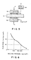
- the area of the portion of the porous member surface as encircled by the O-ring seal 54 is 1 cm2.
- the gaseous fluid such as air is supplied from the gaseous fluid supplying pad 52 in the direction of an arrow A under a pressure of 5 kgf/cm2.
- the gaseous fluid as collected by the collecting pad 53 flows through a flow meter 55, whereby the flow rate is measured or metered. After this, the gaseous fluid is discharged to the atmosphere.
- Figure 6 is a graph showing the results of measurement (metering) of the quantity of gaseous fluid passed through various porous graphite members having been produced with different molding pressures, as described hereinbefore. The measurement was made in the manner described with reference to Figure 5. As illustrated in the graph of Figure 6, it has been confirmed that a desirable flow rate of the gaseous fluid passing through the porous member (which rate is desirable in a gas bearing assembly) is attainable with a molding pressure within a range of 400 - 550 Kgf/cm2. Further, it has been confirmed that, where the molding pressure is within this range, the variation in the flow rate of the passing gaseous fluid at each portion of the bearing surface is satisfactorily suppressed within a narrow range.
- test pieces which were formed respectively of different graphite materials produced respectively in accordance with the above-described production conditions.
- Each test piece was 35 mm in length, 70 mm in width and 5 mm in thickness.
- the tolerance was zero on the plus (+) side of each numerical value but it was not more than 0.1 mm on the minus (-) side.
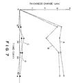
- the amount of change in the thickness of each test piece was measured by use of a measuring device manufactured by Carl-Zeiss, West Germany, and having a resolution of 0.1 micron. From the measured amount of thickness change, the rate of elongation (E) was calculated.
- the value L was measured on the condition that a test piece was dipped in tap water or water-soluble grinding oil diluted with water at the ratio of 1:80 and left therein for 42 days for natural absorption.
- the dipped test pieces were temporarily picked up out of the solution on each of the 11th day, 18th day, 28th day and the 42nd day and, after elapse of 4 hours for temperature stabilization (at 23 ⁇ 5 °C), the thickness was measured.
- test piece made of the conventionall porous graphite material and having a thickness of 5 mm showed expansion of an order of 0.07 % (3.5 microns).
- test piece made of the porous graphite material of the present embodiment showed expansion of an order of only 0.007 % (0.34 micron). Thus, substantially no change in size was noted.
- the porous member usable as a gaseous fluid supplying bearing member in a gas bearing assembly has a thickness in a range of 3 - 7 mm. This is because of the following reason: Where the clearance between the porous member and the shaft to be supported is constant and if the thickness of the porous member is not greater than 3 mm, the flow rate of the passing gaseous fluid becomes too high with the result that there occurs oscillation. If, on the other hand, the thickness is not less than 7 mm, the flow rate of the passing gaseous fluid becomes too low with the result that the rigidity necessary for the gas bearing assembly is not attainable. In any case, the optimum flow rate of the passing gaseous fluid necessary for assuring the rigidity of the gas bearing assembly is not obtainable.
- the clearance should be made small while, on the other hand, it should be made large in a case where the flow rate of the passing gaseous fluid is high.
- MC microbeads meso-carbon microbeads
- the MC microbeads can be produced by a known method such as disclosed, for example, in Japanese Published Patent Application, Publication No. 39633/1975. Now, description will be made of an embodiment of a bearing assembly which uses the MC microbeads as the raw material.
- Table 4 shows typical physical properties of the MC microbeads.
- Figure 8 is a graph similar to the graph of Figure 4 but showing the cumulative distirbution of the particle diameter of the MC microbeads.
- the MC microbeads were used as the raw material and the porous graphite was produced in the following manner:
- the MC microbeads were introduced into rubber molds in accordance with the cold isostatic press molding method. Then, by use of different molding pressures ranging from 350 - 750 Kgf/cm2, a few articles were formed. Thereafter, these articles were calcined (carbonized) by placing them in an ambience of N2 for two hours at a temperature of 1100 °C with the heating rate of 100 °C/h and with a temperature dropping rate of 400 °C/h.
- the calcined articles were graphitized by placing them in an ambience of Ar gas for two hours at a temperature of 2500 °C with both the heating rate and the temperature dropping rate being maintained at 400 °C/h.
- the thus formed carbon members were machined, and final bearing members were obtained.
- these porous bearing members are the same as those of the foregoing example.
- the thus formed bearing members were examined, and the measurement (metering) of the flow rate therethrough and the measurement of the swelling were carried out in the same manner as in the foregoing example.
- the film coating 2 of titanium nitride (TiN) material formed on the shaft 1 surface by the ion plating is effective to prevent seizing of the bearing member with the shaft.
- the porous graphite of the present embodiment has hardness (bearing surface hardness: Hv 1000) which is significantly higher than that of the conventional porous graphite (having the bearing surface hardness: Hv 600).
- the surface film or the titanium nitride material formed on the shaft 1 surface by the ion plating has a high hardness (surface hardness of Hv 1800). Also, the titanium nitride material has self-lubricating properties.
- the provision of the titanium nitride surface coating is effective to prevent the seizing. It has been confirmed by experiments that the advantageous effect of the provision of the titanium nitride coating is retained even in a case where the porous graphite material of the present embodiment having high surface hardness is used.
- a shaft receiving bore 7 of the bearing assembly and the surface of the shaft 1 may be machined in the following manner: First, the shaft receiving bore 7 is finished by machining with a predetermined geometrical precision such as the roundness, cylindricity and otherwise, with the inner diameter being denoted by d3. Subsequently, while taking the optimum bearing clearance as being ⁇ , the shaft 1 is finished by machining with predetermined geometrical precision so that its outer diameter d1 becomes slightly smaller than "d3-2 ⁇ ". After the machining, the shaft 1 is coated with titanium nitride by the ion plating, until the outer diameter d2 including the thickness of the surface coating 2 becomes equal to "d3-2 ⁇ ".
- a predetermined geometrical precision such as the roundness, cylindricity and otherwise
- the film 2 can be formed on the shaft 1 surface with uniform thickness bh the ion plating technique. Further, by suitably setting the conditions of the ion plating treatment, the thickness of the film 2 can be determined easily. For this reason, at the time of machining (cutting, grinding, etc.) of the shaft 1, it is only necessary for the machining operation to finish the shaft 1 surface so as to assure the geometrical precision (roundness, cylindricity, etc.) of an order of submicrons. The exact outer diameter d2 which is finally required in the shaft 1 can be achieved by the formation of the surface coating 2 by the ion plating treatment.
- the provision of the titanium nitride coating on the shaft 1 surface provides various advantageous effects such as follows.
- FIG. 2 there is shown a second embodiment of the present invention.
- the invention is applied to a static pressure thrust and radial gas bearing assembly, and in Figure 2 the assembly is illustrated in a vertical section.
- Denoted at 21 is a rotational shaft having a titanium nitride coating formed on the surface thereof by the ion plating treatment in a similar manner as the case of the shaft 1 of the Figure 1 embodiment.
- Denoted at 22 are thrust plates provided at the opposite ends of the shaft 21. Each thrust plate 22 has a titanium nitride coating provided, by the ion plating treatment, on the surface thereof as opposed to a corresponding thrust bearing surfce 25a of the bearing assembly.
- the static pressure gas bearing assembly of the present embodiment further includes radial bearing members 24 each made of a porous material and having a cylindrical shape; thrust bearing members 25 each made of a porous material and having a ring-like shape; a housing 26; gaseous fluid supplying ports 27; gaseous fluid supplying chambers 28a and 28b; and a fluid exhausting port 29.
- the pressurized gaseous fluid supplied from the supplying ports 27 flows into the fluid supplying chambers 28a and, then, from these chambers the fluid flows into the radial and porous bearing members 24 and is discharged from their bearing surfaces 24a into a minute clearance between the shaft 21 and the bearing surfaces 24a.
- a gaseous film is formed in this clearance.
- the gaseous fluid thus forming the gaseous film and supporting the shaft 21 in the radial direction is exhausted from the port 29.
- the pressurized gaseous fluid supplied from the supplying chambers 28b and passed through the thrust and porous bearing members 25 is discharged from the bearing surfaces 25a into minute clearances defined between the bearing surfaces 25a and the thrust plates 22.
- a gaseous film is formed to support the shaft 21 by way of the thrust plates 22, in the thrust direction.
- the gaseous fluid forming the gaseous film is exhausted while supporting the shaft 21 in the described manner.
- Each of the radial bearing members 24 and the thrust bearing members 25 is made of porous graphite having been produced by molding (by cold isostatic pressing), calcination and graphitization, with its pores being distributed uniformly.
- the porous graphite material of the present invention preferably has a void content in a range of 17 - 20 % with a further effect of preventing both the self-excited vibration and the decrease in the flow rate.
Landscapes
- Chemical & Material Sciences (AREA)
- Engineering & Computer Science (AREA)
- Mechanical Engineering (AREA)
- General Engineering & Computer Science (AREA)
- Chemical Kinetics & Catalysis (AREA)
- Materials Engineering (AREA)
- Metallurgy (AREA)
- Organic Chemistry (AREA)
- Dispersion Chemistry (AREA)
- Magnetic Bearings And Hydrostatic Bearings (AREA)
Applications Claiming Priority (6)
| Application Number | Priority Date | Filing Date | Title |
|---|---|---|---|
| JP23003886A JPS6388317A (ja) | 1986-09-30 | 1986-09-30 | 軸・軸受組立体 |
| JP23003786 | 1986-09-30 | ||
| JP230037/86 | 1986-09-30 | ||
| JP230038/86 | 1986-09-30 | ||
| JP62228578A JP2566789B2 (ja) | 1986-09-30 | 1987-09-14 | 多孔質静圧気体軸受の製造方法 |
| JP228578/87 | 1987-09-14 |
Publications (3)
| Publication Number | Publication Date |
|---|---|
| EP0262939A2 true EP0262939A2 (de) | 1988-04-06 |
| EP0262939A3 EP0262939A3 (en) | 1989-02-08 |
| EP0262939B1 EP0262939B1 (de) | 1993-12-01 |
Family
ID=27331414
Family Applications (1)
| Application Number | Title | Priority Date | Filing Date |
|---|---|---|---|
| EP87308641A Expired - Lifetime EP0262939B1 (de) | 1986-09-30 | 1987-09-29 | Aerostatisches Lager |
Country Status (3)
| Country | Link |
|---|---|
| US (1) | US4838710A (de) |
| EP (1) | EP0262939B1 (de) |
| DE (1) | DE3788331T2 (de) |
Cited By (10)
| Publication number | Priority date | Publication date | Assignee | Title |
|---|---|---|---|---|
| WO1990005247A1 (en) * | 1988-11-09 | 1990-05-17 | Allied-Signal Inc. | High temperature bearing |
| US5017022A (en) * | 1988-11-09 | 1991-05-21 | Allied-Signal, Inc. | High temperature bearing |
| WO1996001956A1 (en) * | 1994-07-07 | 1996-01-25 | The Glacier Metal Company Limited | Back-up bearing arrangement for a magnetic bearing |
| WO2006109039A3 (en) * | 2005-04-15 | 2007-05-03 | Gsi Group Ltd | Gas bearing spindle |
| CN102261984A (zh) * | 2011-04-18 | 2011-11-30 | 中国计量学院 | 一种静压气浮轴承振动特性的检测装置 |
| WO2014081901A1 (en) * | 2012-11-20 | 2014-05-30 | New Way Machine Components, Inc. | Air bearing for use as seal |
| EP2800917A4 (de) * | 2012-01-03 | 2015-11-25 | New Way Machine Components Inc | Luftlager zur verwendung als dichtung |
| EP3201497A4 (de) * | 2014-09-29 | 2018-05-30 | New Way Machine Components, Inc. | Entlüftungslose dichtung für poröse medien |
| CN108895086A (zh) * | 2018-09-20 | 2018-11-27 | 燕山大学 | 一种带有金属橡胶环的空气静压轴承 |
| US10598222B2 (en) | 2012-01-03 | 2020-03-24 | New Way Machine Components, Inc. | Air bearing for use as seal |
Families Citing this family (29)
| Publication number | Priority date | Publication date | Assignee | Title |
|---|---|---|---|---|
| JPH02271106A (ja) * | 1989-04-10 | 1990-11-06 | Hitachi Ltd | すべり軸受装置 |
| DE3939004A1 (de) * | 1989-11-25 | 1991-05-29 | Kugelfischer G Schaefer & Co | Luftgelagerte verlegerolle |
| US5295330A (en) * | 1992-09-08 | 1994-03-22 | Hoffman Steve E | Fluid thrust bearing centrifugal disk finisher |
| JP3086764B2 (ja) * | 1993-02-22 | 2000-09-11 | キヤノン株式会社 | 静圧軸受装置 |
| US5718516A (en) * | 1996-04-02 | 1998-02-17 | Sae Magnetics (H.K.) Ltd. | Spindle motors with hard coated hydrodynamic bearings |
| JP3860253B2 (ja) * | 1996-04-30 | 2006-12-20 | 黒田精工株式会社 | 静圧気体軸受 |
| DE19630476A1 (de) * | 1996-07-27 | 1998-01-29 | Rieter Ingolstadt Spinnerei | Offenend-Spinnvorrichtung |
| DE19630477A1 (de) * | 1996-07-27 | 1998-01-29 | Rieter Ingolstadt Spinnerei | Offenend-Spinnvorrichtung |
| US5833370A (en) * | 1996-08-21 | 1998-11-10 | Japan Servo Co., Ltd. | Oil-retaining bearing structure for rotary machine |
| JP2002503317A (ja) * | 1997-04-17 | 2002-01-29 | ザ ティムケン カンパニー | 回転空気軸受及びその製造方法 |
| US5887985A (en) * | 1997-07-24 | 1999-03-30 | Thermo Cardiosystems Inc. | Wear-resistant bearings |
| DE19738919C1 (de) * | 1997-09-05 | 1999-04-29 | Maxon Motor Gmbh | Verfahren zur Herstellung eines Gleitlagers und Gleitlager |
| US5998898A (en) * | 1997-12-19 | 1999-12-07 | Matsushita Electric Industrial Co., Ltd. | Motor having hydrodynamic bearing |
| RU2186268C2 (ru) * | 1999-07-19 | 2002-07-27 | Комсомольский-на-Амуре государственный технический университет | Пористый вкладыш газостатического подшипника и способ его обработки |
| US7052182B2 (en) * | 2000-02-01 | 2006-05-30 | Toto Ltd. | Hydrostatic gas bearing, hydrostatic gas bearing device for use in vacuum environment, and gas recovering method for the hydrostatic gas bearing device |
| US6515288B1 (en) * | 2000-03-16 | 2003-02-04 | Applied Materials, Inc. | Vacuum bearing structure and a method of supporting a movable member |
| JP2002075855A (ja) * | 2000-06-14 | 2002-03-15 | Canon Inc | 自重補償装置およびこれを用いたステージ装置並びに露光装置およびそれを用いたデバイス製造方法 |
| US6502991B2 (en) | 2001-03-14 | 2003-01-07 | The Timken Company | Rotary fluid bearing coatings and coining and processes for manufacturing the same |
| US6547439B2 (en) * | 2001-04-10 | 2003-04-15 | Yen Sun Technology Corp. | Bearing device |
| GB0304320D0 (en) * | 2003-02-26 | 2003-04-02 | Bladon Jets Ltd | Gas turbine engines |
| US7429132B1 (en) | 2005-08-16 | 2008-09-30 | Florida Turbine Technologies, Inc. | Hydrostatic air bearing with a porous metal ring |
| JP4992986B2 (ja) * | 2010-01-22 | 2012-08-08 | 新東工業株式会社 | 静圧軸受装置および静圧軸受装置を備えたステージ |
| CN102061946A (zh) * | 2010-11-16 | 2011-05-18 | 苏州制氧机有限责任公司 | 增压透平膨胀机 |
| WO2014045270A1 (en) | 2012-09-23 | 2014-03-27 | Ettem Engineering S.A. Ltd | Compliant fluid-film riding taper bearing |
| CA2834615C (en) * | 2013-08-28 | 2020-04-28 | Gedex Systems Inc. | Single axis rotational gas bearing with feed-through |
| US9429191B2 (en) * | 2013-10-11 | 2016-08-30 | General Electric Company | Journal bearing assemblies and methods of assembling same |
| WO2016149203A1 (en) * | 2015-03-13 | 2016-09-22 | New Way Machine Components, Inc. | Externally pressurized porous media gas bearing for use in valves and preventing fugitive emissions of the same |
| US10557501B1 (en) * | 2018-12-21 | 2020-02-11 | Metal Industries Research & Development Centre | Noncontact fluid bearing and manufacturing method thereof |
| JPWO2021124978A1 (de) * | 2019-12-18 | 2021-06-24 |
Family Cites Families (14)
| Publication number | Priority date | Publication date | Assignee | Title |
|---|---|---|---|---|
| US2645534A (en) * | 1950-02-10 | 1953-07-14 | Gen Electric | Pressurized bearing |
| FR1061978A (fr) * | 1952-05-23 | 1954-04-16 | Etude Et D Expl Du Palier Flui | Palier perméable |
| FR1377414A (fr) * | 1963-09-13 | 1964-11-06 | Metallurgie Francaise | Coussinet autolubrifiant |
| US3349462A (en) * | 1966-06-14 | 1967-10-31 | Lambert H Mott | Air roller |
| US3645590A (en) * | 1970-12-17 | 1972-02-29 | Gen Motors Corp | Carbon-graphite gas-bearing roll |
| JPS5018879A (de) * | 1973-06-20 | 1975-02-27 | ||
| JPS5143979B2 (de) * | 1973-08-15 | 1976-11-25 | ||
| US4013326A (en) * | 1976-04-02 | 1977-03-22 | General Motors Corporation | Gas bearing roll shell assembly with preload means |
| DE2712126A1 (de) * | 1977-03-19 | 1978-09-21 | Langlet Geb Boeckheler Sofie S | Gleitlager |
| CH640885A5 (de) * | 1978-07-21 | 1984-01-31 | Suisse Horlogerie Rech Lab | Mit einem harten ueberzug versehene maschinenelemente. |
| DE3110712C2 (de) * | 1981-03-19 | 1986-08-07 | Joachim Prof. Dr.-Ing. 8000 München Heinzl | Aerostatisches Lager |
| CH653581A5 (de) * | 1982-03-05 | 1986-01-15 | Bbc Brown Boveri & Cie | Verfahren zur herstellung einer grossflaechigen platte oder folie aus poroesem titan. |
| DE3230232A1 (de) * | 1982-08-13 | 1984-02-16 | Interatom Internationale Atomreaktorbau Gmbh, 5060 Bergisch Gladbach | Lagerschale fuer ein gasstatisches lager und verfahren zu seiner herstellung |
| JPH03137189A (ja) * | 1983-06-30 | 1991-06-11 | Kasei Optonix Co Ltd | 燐酸塩蛍光体の製造方法 |
-
1987
- 1987-09-29 DE DE87308641T patent/DE3788331T2/de not_active Expired - Fee Related
- 1987-09-29 EP EP87308641A patent/EP0262939B1/de not_active Expired - Lifetime
- 1987-09-29 US US07/102,358 patent/US4838710A/en not_active Expired - Lifetime
Cited By (18)
| Publication number | Priority date | Publication date | Assignee | Title |
|---|---|---|---|---|
| WO1990005247A1 (en) * | 1988-11-09 | 1990-05-17 | Allied-Signal Inc. | High temperature bearing |
| US5017022A (en) * | 1988-11-09 | 1991-05-21 | Allied-Signal, Inc. | High temperature bearing |
| WO1996001956A1 (en) * | 1994-07-07 | 1996-01-25 | The Glacier Metal Company Limited | Back-up bearing arrangement for a magnetic bearing |
| US5693994A (en) * | 1994-07-07 | 1997-12-02 | The Glacier Metal Company Limited | Back-up bearing arrangement for a magnetic bearing |
| DE112006000916B4 (de) * | 2005-04-15 | 2013-12-12 | Gsi Group Ltd. | Gaslagerspindeln |
| GB2440299A (en) * | 2005-04-15 | 2008-01-23 | Gsi Group Ltd | Gas bearing spindle |
| GB2440299B (en) * | 2005-04-15 | 2008-10-01 | Gsi Group Ltd | Gas bearing spindle |
| WO2006109039A3 (en) * | 2005-04-15 | 2007-05-03 | Gsi Group Ltd | Gas bearing spindle |
| CN102261984A (zh) * | 2011-04-18 | 2011-11-30 | 中国计量学院 | 一种静压气浮轴承振动特性的检测装置 |
| US9441668B2 (en) | 2012-01-03 | 2016-09-13 | New Way Machine Components, Inc. | Air bearing for use as seal |
| EP2800917A4 (de) * | 2012-01-03 | 2015-11-25 | New Way Machine Components Inc | Luftlager zur verwendung als dichtung |
| US10598222B2 (en) | 2012-01-03 | 2020-03-24 | New Way Machine Components, Inc. | Air bearing for use as seal |
| US11619263B2 (en) | 2012-01-03 | 2023-04-04 | New Way Machine Components, Inc. | Externally pressurized oil-free freon bearing |
| US12044272B2 (en) | 2012-01-03 | 2024-07-23 | New Way Machine Components, Inc. | Air bearing for use as seal |
| WO2014081901A1 (en) * | 2012-11-20 | 2014-05-30 | New Way Machine Components, Inc. | Air bearing for use as seal |
| EP3201497A4 (de) * | 2014-09-29 | 2018-05-30 | New Way Machine Components, Inc. | Entlüftungslose dichtung für poröse medien |
| US10030666B2 (en) | 2014-09-29 | 2018-07-24 | New Way Machine Components, Inc. | Porous media ventless seal |
| CN108895086A (zh) * | 2018-09-20 | 2018-11-27 | 燕山大学 | 一种带有金属橡胶环的空气静压轴承 |
Also Published As
| Publication number | Publication date |
|---|---|
| EP0262939B1 (de) | 1993-12-01 |
| US4838710A (en) | 1989-06-13 |
| DE3788331T2 (de) | 1994-04-28 |
| DE3788331D1 (de) | 1994-01-13 |
| EP0262939A3 (en) | 1989-02-08 |
Similar Documents
| Publication | Publication Date | Title |
|---|---|---|
| EP0262939A2 (de) | Aerostatisches Lager | |
| Lancaster | Dry bearings: a survey of materials and factors affecting their performance | |
| EP0454616B1 (de) | Wälzkörper, Verfahren zu seiner Herstellung und Wälzkörper- oder Gleitlager | |
| WO1995023122A1 (en) | Self-sintered silicon carbide/carbon composite__________________ | |
| US5538649A (en) | Carbon composite mateiral for tribological applications | |
| JPH07332367A (ja) | 三様式の細孔構成を有する多孔性SiCのベアリング材料及びその製造方法 | |
| EP0864549B1 (de) | Gesintertes Siliciumcarbid mit Graphitzusatz, dasselbe enthaltender Sinterverbund, und mechanische Dichtung | |
| JP5637513B2 (ja) | 摺動材料およびメカニカルシール | |
| US7166550B2 (en) | Ceramic composite body of silicon carbide/boron nitride/carbon | |
| EP1988067B1 (de) | Gesinterte keramik, schiebeteil dafür und verfahren zur herstellung gesinterter keramik | |
| JP3654861B2 (ja) | Cmp装置用ロータリジョイント | |
| JPS63186030A (ja) | 多孔質静圧気体軸受の製造方法 | |
| JP4209484B2 (ja) | 摺動用炭素材、摺動用炭素材を用いたシール材及び摺動用炭素材の製造方法 | |
| JP3764089B2 (ja) | 複合SiC摺動部材、メカニカルシール用密封環、メカニカルシール、及び複合SiC摺動部材の製造方法 | |
| Kwan | Processing and fluid flow characteristics of hot isostatically pressed porous alumina for aerostatic bearing applications | |
| JPH0379746A (ja) | 連続溶融金属めっき用ロール及びそれを用いた装置 | |
| EP0708067A1 (de) | Keramisches Material und Verfahren zur Herstellung eines keramischen Produktes welches dieses verwendet | |
| KR100559790B1 (ko) | 다공질 세라믹을 이용한 정압 공기베어링 | |
| JP4913468B2 (ja) | 炭化珪素系研磨プレートおよび半導体ウェーハの研磨方法 | |
| JPS62210275A (ja) | ベ−ンポンプ | |
| JPS62148384A (ja) | 炭化珪素質複合材料 | |
| JPH0226818A (ja) | 炭素材料 | |
| US20240253268A1 (en) | Bimodal cemented carbide powders for additive manufacturing and structured bodies made therefrom | |
| JPS62234223A (ja) | 薄膜磁気ヘツドスライダおよびその製造方法 | |
| JP2752417B2 (ja) | アルミナー二硫化モリブデン系複合材料の製法 |
Legal Events
| Date | Code | Title | Description |
|---|---|---|---|
| PUAI | Public reference made under article 153(3) epc to a published international application that has entered the european phase |
Free format text: ORIGINAL CODE: 0009012 |
|
| AK | Designated contracting states |
Kind code of ref document: A2 Designated state(s): DE FR GB NL SE |
|
| PUAL | Search report despatched |
Free format text: ORIGINAL CODE: 0009013 |
|
| AK | Designated contracting states |
Kind code of ref document: A3 Designated state(s): DE FR GB NL SE |
|
| 17P | Request for examination filed |
Effective date: 19890705 |
|
| 17Q | First examination report despatched |
Effective date: 19910715 |
|
| GRAA | (expected) grant |
Free format text: ORIGINAL CODE: 0009210 |
|
| AK | Designated contracting states |
Kind code of ref document: B1 Designated state(s): DE FR GB NL SE |
|
| REF | Corresponds to: |
Ref document number: 3788331 Country of ref document: DE Date of ref document: 19940113 |
|
| ET | Fr: translation filed | ||
| PLBE | No opposition filed within time limit |
Free format text: ORIGINAL CODE: 0009261 |
|
| STAA | Information on the status of an ep patent application or granted ep patent |
Free format text: STATUS: NO OPPOSITION FILED WITHIN TIME LIMIT |
|
| 26N | No opposition filed | ||
| EAL | Se: european patent in force in sweden |
Ref document number: 87308641.7 |
|
| REG | Reference to a national code |
Ref country code: GB Ref legal event code: IF02 |
|
| PGFP | Annual fee paid to national office [announced via postgrant information from national office to epo] |
Ref country code: FR Payment date: 20050914 Year of fee payment: 19 |
|
| PGFP | Annual fee paid to national office [announced via postgrant information from national office to epo] |
Ref country code: NL Payment date: 20050915 Year of fee payment: 19 |
|
| PGFP | Annual fee paid to national office [announced via postgrant information from national office to epo] |
Ref country code: GB Payment date: 20050916 Year of fee payment: 19 |
|
| PGFP | Annual fee paid to national office [announced via postgrant information from national office to epo] |
Ref country code: SE Payment date: 20050920 Year of fee payment: 19 |
|
| PGFP | Annual fee paid to national office [announced via postgrant information from national office to epo] |
Ref country code: DE Payment date: 20051118 Year of fee payment: 19 |
|
| PG25 | Lapsed in a contracting state [announced via postgrant information from national office to epo] |
Ref country code: SE Free format text: LAPSE BECAUSE OF NON-PAYMENT OF DUE FEES Effective date: 20060930 |
|
| PG25 | Lapsed in a contracting state [announced via postgrant information from national office to epo] |
Ref country code: NL Free format text: LAPSE BECAUSE OF NON-PAYMENT OF DUE FEES Effective date: 20070401 |
|
| PG25 | Lapsed in a contracting state [announced via postgrant information from national office to epo] |
Ref country code: DE Free format text: LAPSE BECAUSE OF NON-PAYMENT OF DUE FEES Effective date: 20070403 |
|
| EUG | Se: european patent has lapsed | ||
| GBPC | Gb: european patent ceased through non-payment of renewal fee |
Effective date: 20060929 |
|
| NLV4 | Nl: lapsed or anulled due to non-payment of the annual fee |
Effective date: 20070401 |
|
| REG | Reference to a national code |
Ref country code: FR Ref legal event code: ST Effective date: 20070531 |
|
| PG25 | Lapsed in a contracting state [announced via postgrant information from national office to epo] |
Ref country code: GB Free format text: LAPSE BECAUSE OF NON-PAYMENT OF DUE FEES Effective date: 20060929 |
|
| PG25 | Lapsed in a contracting state [announced via postgrant information from national office to epo] |
Ref country code: FR Free format text: LAPSE BECAUSE OF NON-PAYMENT OF DUE FEES Effective date: 20061002 |