EP0263281A1 - Mouton de forage pneumatique - Google Patents
Mouton de forage pneumatique Download PDFInfo
- Publication number
- EP0263281A1 EP0263281A1 EP87112220A EP87112220A EP0263281A1 EP 0263281 A1 EP0263281 A1 EP 0263281A1 EP 87112220 A EP87112220 A EP 87112220A EP 87112220 A EP87112220 A EP 87112220A EP 0263281 A1 EP0263281 A1 EP 0263281A1
- Authority
- EP
- European Patent Office
- Prior art keywords
- boring machine
- ram boring
- hollow cylinder
- machine according
- exhaust air
- Prior art date
- Legal status (The legal status is an assumption and is not a legal conclusion. Google has not performed a legal analysis and makes no representation as to the accuracy of the status listed.)
- Granted
Links
Images

Classifications
-
- F—MECHANICAL ENGINEERING; LIGHTING; HEATING; WEAPONS; BLASTING
- F01—MACHINES OR ENGINES IN GENERAL; ENGINE PLANTS IN GENERAL; STEAM ENGINES
- F01N—GAS-FLOW SILENCERS OR EXHAUST APPARATUS FOR MACHINES OR ENGINES IN GENERAL; GAS-FLOW SILENCERS OR EXHAUST APPARATUS FOR INTERNAL-COMBUSTION ENGINES
- F01N1/00—Silencing apparatus characterised by method of silencing
- F01N1/08—Silencing apparatus characterised by method of silencing by reducing exhaust energy by throttling or whirling
- F01N1/082—Silencing apparatus characterised by method of silencing by reducing exhaust energy by throttling or whirling by passing the exhaust gases through porous members
-
- B—PERFORMING OPERATIONS; TRANSPORTING
- B25—HAND TOOLS; PORTABLE POWER-DRIVEN TOOLS; MANIPULATORS
- B25D—PERCUSSIVE TOOLS
- B25D17/00—Details of, or accessories for, portable power-driven percussive tools
- B25D17/11—Arrangements of noise-damping means
- B25D17/12—Arrangements of noise-damping means of exhaust silencers
-
- E—FIXED CONSTRUCTIONS
- E21—EARTH OR ROCK DRILLING; MINING
- E21B—EARTH OR ROCK DRILLING; OBTAINING OIL, GAS, WATER, SOLUBLE OR MELTABLE MATERIALS OR A SLURRY OF MINERALS FROM WELLS
- E21B21/00—Methods or apparatus for flushing boreholes, e.g. by use of exhaust air from motor
- E21B21/002—Down-hole drilling fluid separation systems
-
- E—FIXED CONSTRUCTIONS
- E21—EARTH OR ROCK DRILLING; MINING
- E21B—EARTH OR ROCK DRILLING; OBTAINING OIL, GAS, WATER, SOLUBLE OR MELTABLE MATERIALS OR A SLURRY OF MINERALS FROM WELLS
- E21B4/00—Drives for drilling, used in the borehole
- E21B4/06—Down-hole impacting means, e.g. hammers
- E21B4/14—Fluid operated hammers
- E21B4/145—Fluid operated hammers of the self propelled-type, e.g. with a reverse mode to retract the device from the hole
-
- E—FIXED CONSTRUCTIONS
- E21—EARTH OR ROCK DRILLING; MINING
- E21B—EARTH OR ROCK DRILLING; OBTAINING OIL, GAS, WATER, SOLUBLE OR MELTABLE MATERIALS OR A SLURRY OF MINERALS FROM WELLS
- E21B7/00—Special methods or apparatus for drilling
- E21B7/20—Driving or forcing casings or pipes into boreholes, e.g. sinking; Simultaneously drilling and casing boreholes
- E21B7/205—Driving or forcing casings or pipes into boreholes, e.g. sinking; Simultaneously drilling and casing boreholes without earth removal
- E21B7/206—Driving or forcing casings or pipes into boreholes, e.g. sinking; Simultaneously drilling and casing boreholes without earth removal using down-hole drives
-
- Y—GENERAL TAGGING OF NEW TECHNOLOGICAL DEVELOPMENTS; GENERAL TAGGING OF CROSS-SECTIONAL TECHNOLOGIES SPANNING OVER SEVERAL SECTIONS OF THE IPC; TECHNICAL SUBJECTS COVERED BY FORMER USPC CROSS-REFERENCE ART COLLECTIONS [XRACs] AND DIGESTS
- Y10—TECHNICAL SUBJECTS COVERED BY FORMER USPC
- Y10S—TECHNICAL SUBJECTS COVERED BY FORMER USPC CROSS-REFERENCE ART COLLECTIONS [XRACs] AND DIGESTS
- Y10S173/00—Tool driving or impacting
- Y10S173/02—Sound muffling
Definitions
- the invention relates to a pneumatic ram boring machine in which an axially reciprocating piston delivers its impact energy to the housing and / or its impact tip.
- Ram boring machines also known as ground rockets, are primarily used to lay water or electricity supply lines and telephone cables without having to tear down the pavement or sidewalks. They usually have a percussion tip which is actuated by a pneumatically operated percussion piston. When the percussion tip is propelled, the percussion piston is moved back and forth in a tubular housing in that compressed air supplied via a compressed air line alternately acts on the front and rear foreheads of the percussion piston. Through openings in the rear end of the housing allow the exhaust air to exit into the earth channel created by the ram boring machine and from there to the outside.
- compressed air lubricants such as B. mineral oils or other additives. These additives are released as a mist together with the exhaust air and pose a danger to the operating personnel and the environment.
- the noise generated by most ram boring machines often exceeds the permanently harmful level of 90 dBA. This level is usually exceeded even with a ram boring machine that mainly works below the surface. In particular, if a pipe is pulled in at the same time as the ramming, considerable noise escapes because the pipe acts like a sound pipe.
- the invention has for its object to provide a ram boring machine which reduces some of the environmental impairments accompanying the operation of such compressed air devices.
- This object is achieved according to the invention in a ram boring machine of the type mentioned at the outset by an air-permeable hollow cylinder arranged in the exhaust air flow and having a sound-absorbing and / or an oil-separating filling.
- the hollow cylinder has a central passage, it can be pulled over the compressed air line of the ram boring machine; it can also have a concentric pipe section, for example with protruding threads for screwing with two sections of the compressed air line.
- the hollow cylinder then fills approximately the free annular space between the compressed air line and the wall of the earth channel created by the ram boring machine, so that essentially all of the exhaust air is conditioned.
- the hollow cylinder can also have a cable connection on at least one end face, in order to be able to tension a cable between the rear end of the ram boring machine and the hollow cylinder and / or the hollow cylinder and a pulling tube.
- the filter can also be arranged directly at the rear end of the ram boring machine or at a distance in a pipe pulled by the machine, since its outside diameter is adapted to the outside diameter of the compressed air device. In any case, it is ensured that practically no exhaust air escapes without having passed the filter.
- the hollow cylinder can have holes in its end faces serving as passages for the exhaust air coming from the ram boring machine. If the exhaust air inlet holes and the exhaust air outlet holes are opposite one another, an air passage which is only damped by the filling but is otherwise unimpeded is ensured.
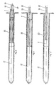
- the filter 1 consists of a hollow cylinder 2, the end faces 3, 4 of which each have a central circular opening 5 for a tube piece 6 of smaller diameter and slightly greater length arranged concentrically to the cylinder 2 for pulling through a compressed air line 10 and further with their center points arranged concentrically to the opening 5 Have holes 7, 8.
- filter materials 9, 11 for filtering and soundproofing the exhaust air flow.
- the filter can also be arranged between two sections of the compressed air line 10, it then migrates with the compressed air line in accordance with the device advance.
- the filter 1 is arranged in a pneumatically operated ram boring machine 12 in such a way that the compressed air reaches the ram boring machine 12 in the direction of arrow 14, then the exhaust air penetrates through the holes 7 on the end face 3 into the sound-absorbing filling 9 and then into the oil-separating filling 11 and finally emerges from the holes 8 on the end face 5.
- the filter 1 can be arranged directly at the rear end of the ram boring machine 12 (FIG. 3), at the beginning of the earth channel 13 created by the ram boring machine 12 (FIG. 4) or in a protective tube 15 drawn by the ram boring machine 12 (FIG. 5).
- the ram boring machine 12 is provided with a control line 16 and a pull rope 17, the hollow cylinder preferably has a corresponding, axially parallel passage, not shown in the drawing on.
- the pull rope can also be attached directly to the hollow cylinder.
- Its outer diameter corresponds to that of the ram boring machine or that of the protective tube, so that practically no exhaust air can escape unfiltered.
- the filter according to the invention substantially reduces the sound level of the exhaust air of 100 dBA in ram boring machines and removes oil to a high percentage from the exhaust air. This is of particular importance because ram boring machines of the type in question are mostly used in densely populated and / or busy areas for trenchless laying of supply lines.
Landscapes
- Engineering & Computer Science (AREA)
- Geology (AREA)
- Life Sciences & Earth Sciences (AREA)
- Mining & Mineral Resources (AREA)
- Mechanical Engineering (AREA)
- Physics & Mathematics (AREA)
- Environmental & Geological Engineering (AREA)
- Fluid Mechanics (AREA)
- General Life Sciences & Earth Sciences (AREA)
- Geochemistry & Mineralogy (AREA)
- Chemical & Material Sciences (AREA)
- Combustion & Propulsion (AREA)
- General Engineering & Computer Science (AREA)
- Earth Drilling (AREA)
Priority Applications (1)
| Application Number | Priority Date | Filing Date | Title |
|---|---|---|---|
| AT87112220T ATE57644T1 (de) | 1986-10-10 | 1987-08-22 | Pneumatisches rammbohrgeraet. |
Applications Claiming Priority (2)
| Application Number | Priority Date | Filing Date | Title |
|---|---|---|---|
| DE3634579 | 1986-10-10 | ||
| DE19863634579 DE3634579A1 (de) | 1986-10-10 | 1986-10-10 | Pneumatisches rammbohrgeraet |
Publications (2)
| Publication Number | Publication Date |
|---|---|
| EP0263281A1 true EP0263281A1 (fr) | 1988-04-13 |
| EP0263281B1 EP0263281B1 (fr) | 1990-10-24 |
Family
ID=6311485
Family Applications (1)
| Application Number | Title | Priority Date | Filing Date |
|---|---|---|---|
| EP87112220A Expired - Lifetime EP0263281B1 (fr) | 1986-10-10 | 1987-08-22 | Mouton de forage pneumatique |
Country Status (5)
| Country | Link |
|---|---|
| US (1) | US4840234A (fr) |
| EP (1) | EP0263281B1 (fr) |
| JP (1) | JPS63107686A (fr) |
| AT (1) | ATE57644T1 (fr) |
| DE (1) | DE3634579A1 (fr) |
Cited By (4)
| Publication number | Priority date | Publication date | Assignee | Title |
|---|---|---|---|---|
| WO1991012987A1 (fr) * | 1990-03-02 | 1991-09-05 | Desinsectisation Moderne | Sonde autopropulsee, notamment pour penetrer dans une matiere pulverulente |
| FR2659111A1 (fr) * | 1990-03-02 | 1991-09-06 | Desinsectisation Moderne | Sonde comprenant des moyens d'echappement d'air. |
| FR2659112A1 (fr) * | 1990-03-02 | 1991-09-06 | Desinsectisation Moderne | Sonde pour penetrer et se deplacer dans une masse de matiere pulverulente. |
| EP0694675A1 (fr) * | 1994-07-30 | 1996-01-31 | Tracto-Technik Paul Schmidt Spezialmaschinen Kg | Dispositif de fixation et de maintien en tension d'un câble de traction fixé à un mouton de forage |
Families Citing this family (1)
| Publication number | Priority date | Publication date | Assignee | Title |
|---|---|---|---|---|
| US20080148697A1 (en) * | 2006-12-20 | 2008-06-26 | Chia Sheng Liang | Filter for Nail Gun |
Citations (8)
| Publication number | Priority date | Publication date | Assignee | Title |
|---|---|---|---|---|
| DE14978C (de) * | Gildemeister & Kamp in Dortmund | Neuerungen an Bohrapparaten zum Aufbohren von Ueberhauen | ||
| CH351921A (de) * | 1958-01-10 | 1961-01-31 | Ganz Rudolf | Presslufthammer |
| CH378820A (de) * | 1960-03-18 | 1964-06-15 | Sig Schweiz Industrieges | Schalldämpfer an Pressluftwerkzeug |
| US4134472A (en) * | 1977-08-29 | 1979-01-16 | Trainor John B | Combination muffler and air filter |
| US4144941A (en) * | 1977-09-30 | 1979-03-20 | Ritter Lester L | Directional impact tool for tunneling |
| US4196783A (en) * | 1978-07-11 | 1980-04-08 | Lofs Verkstads Ab | Device for boring |
| CA1155400A (fr) * | 1981-02-09 | 1983-10-18 | George H. Williams | Silencieux |
| US4424883A (en) * | 1981-03-31 | 1984-01-10 | Panda S.R.L. | Silencer for pneumatic equipment |
Family Cites Families (3)
| Publication number | Priority date | Publication date | Assignee | Title |
|---|---|---|---|---|
| US3115209A (en) * | 1960-05-11 | 1963-12-24 | Edward A Bembinster | Muffler |
| US3981378A (en) * | 1974-10-16 | 1976-09-21 | Horn Construction Co., Inc. | Muffler for pile driving apparatus |
| US4184564A (en) * | 1977-08-29 | 1980-01-22 | Trainor John B | Combination muffler and air filter |
-
1986
- 1986-10-10 DE DE19863634579 patent/DE3634579A1/de not_active Withdrawn
-
1987
- 1987-08-22 EP EP87112220A patent/EP0263281B1/fr not_active Expired - Lifetime
- 1987-08-22 AT AT87112220T patent/ATE57644T1/de not_active IP Right Cessation
- 1987-10-05 US US07/105,104 patent/US4840234A/en not_active Expired - Fee Related
- 1987-10-09 JP JP62256131A patent/JPS63107686A/ja active Pending
Patent Citations (8)
| Publication number | Priority date | Publication date | Assignee | Title |
|---|---|---|---|---|
| DE14978C (de) * | Gildemeister & Kamp in Dortmund | Neuerungen an Bohrapparaten zum Aufbohren von Ueberhauen | ||
| CH351921A (de) * | 1958-01-10 | 1961-01-31 | Ganz Rudolf | Presslufthammer |
| CH378820A (de) * | 1960-03-18 | 1964-06-15 | Sig Schweiz Industrieges | Schalldämpfer an Pressluftwerkzeug |
| US4134472A (en) * | 1977-08-29 | 1979-01-16 | Trainor John B | Combination muffler and air filter |
| US4144941A (en) * | 1977-09-30 | 1979-03-20 | Ritter Lester L | Directional impact tool for tunneling |
| US4196783A (en) * | 1978-07-11 | 1980-04-08 | Lofs Verkstads Ab | Device for boring |
| CA1155400A (fr) * | 1981-02-09 | 1983-10-18 | George H. Williams | Silencieux |
| US4424883A (en) * | 1981-03-31 | 1984-01-10 | Panda S.R.L. | Silencer for pneumatic equipment |
Cited By (5)
| Publication number | Priority date | Publication date | Assignee | Title |
|---|---|---|---|---|
| WO1991012987A1 (fr) * | 1990-03-02 | 1991-09-05 | Desinsectisation Moderne | Sonde autopropulsee, notamment pour penetrer dans une matiere pulverulente |
| FR2659111A1 (fr) * | 1990-03-02 | 1991-09-06 | Desinsectisation Moderne | Sonde comprenant des moyens d'echappement d'air. |
| FR2659112A1 (fr) * | 1990-03-02 | 1991-09-06 | Desinsectisation Moderne | Sonde pour penetrer et se deplacer dans une masse de matiere pulverulente. |
| US5377551A (en) * | 1990-03-02 | 1995-01-03 | Desinsectisation Moderne | Probe for penetrating and displacing particularly into a mass of pulverulent material |
| EP0694675A1 (fr) * | 1994-07-30 | 1996-01-31 | Tracto-Technik Paul Schmidt Spezialmaschinen Kg | Dispositif de fixation et de maintien en tension d'un câble de traction fixé à un mouton de forage |
Also Published As
| Publication number | Publication date |
|---|---|
| US4840234A (en) | 1989-06-20 |
| DE3634579A1 (de) | 1988-04-21 |
| EP0263281B1 (fr) | 1990-10-24 |
| ATE57644T1 (de) | 1990-11-15 |
| JPS63107686A (ja) | 1988-05-12 |
Similar Documents
| Publication | Publication Date | Title |
|---|---|---|
| DE2814717C3 (de) | Schalldämpfende Vorrichtung zur Dämpfung des sich in einem Luftkanal ausbreitenden Geräuschs | |
| EP0255686A2 (fr) | Méthode pour la fabrication d'un élément optique de transmission rempli et dispositif pour la réalisation de la méthode | |
| DE69229099T2 (de) | Vorrichtung zur Installation eines Drahtes | |
| EP0263281B1 (fr) | Mouton de forage pneumatique | |
| EP0735303A1 (fr) | Procédé de pose de canalisations enterrées entre des regards d'égout | |
| EP1790895B1 (fr) | Passage traversant un mur ou un plafond | |
| DE3501215C2 (fr) | ||
| DE3603238A1 (de) | Verfahren zur erneuerung von abwasserleitungen und vorrichtung zur durchfuehrung des verfahrens | |
| DE19745918A1 (de) | Verfahren und Vorrichtung zum Einziehen mindestens eines langgestreckten, flexiblen Elementes in ein Kanalsystem | |
| DE1450446A1 (de) | Einrichtung zur Daempfung der Schwingungen eines pulsierenden Fluessigkeitsstromes | |
| DE102013007533B4 (de) | "Vorrichtung zum Einbringen eines Neurohres in ein Altrohr mittels eines selbstgetriebenen Schlaggerätes" | |
| DE102010041100A1 (de) | Entgasung | |
| DE3731611A1 (de) | Verfahren und einrichtung zum nachtraeglichen einziehen von kabeln in kabelschutzrohre | |
| EP0468091B1 (fr) | Méthode pour la fabrication et l'installation de sorties d'air | |
| AT393982B (de) | Druckluftnagelgeraet | |
| DE2123783A1 (de) | Vorrichtung zur Handhabung flexibler Versorgungsleitungen | |
| DE1810367U (de) | Vorrichtung zum abdichten der ein- und ausfuehrungsoeffnungen fuer kabel in rohren. | |
| AT504215B1 (de) | Verfahren und vorrichtung zum einziehen von kabeln und/oder leitungen | |
| EP0361055A1 (fr) | Dispositif pour dériver des tuyaux souples à haut pression | |
| DE4013548A1 (de) | Verfahren und einrichtung zum einziehen eines kabels in ein kabelschutzrohr | |
| DE3433745C2 (de) | Vorrichtung zum Bearbeiten von Material mit einem Flüssigkeitsstrahl hoher Geschwindigkeit | |
| DE202025103713U1 (de) | Zyklondüse | |
| EP1120623A1 (fr) | Dispositif et procédé de nettoyage de tubes d'échangeur de chaleur | |
| DE8531635U1 (de) | Druckluftbetriebenes Gerät zur Gesteinsbearbeitung | |
| DE2655935A1 (de) | Aufspreizbare vorrichtung zum befestigen von rohrfoermigen wickelhuelsen auf spindeln |
Legal Events
| Date | Code | Title | Description |
|---|---|---|---|
| PUAI | Public reference made under article 153(3) epc to a published international application that has entered the european phase |
Free format text: ORIGINAL CODE: 0009012 |
|
| AK | Designated contracting states |
Kind code of ref document: A1 Designated state(s): AT BE CH ES FR GB GR IT LI LU NL SE |
|
| 17P | Request for examination filed |
Effective date: 19880709 |
|
| 17Q | First examination report despatched |
Effective date: 19890419 |
|
| GRAA | (expected) grant |
Free format text: ORIGINAL CODE: 0009210 |
|
| ITF | It: translation for a ep patent filed | ||
| AK | Designated contracting states |
Kind code of ref document: B1 Designated state(s): AT BE CH ES FR GB GR IT LI LU NL SE |
|
| PG25 | Lapsed in a contracting state [announced via postgrant information from national office to epo] |
Ref country code: SE Effective date: 19901024 Ref country code: GR Free format text: LAPSE BECAUSE OF FAILURE TO SUBMIT A TRANSLATION OF THE DESCRIPTION OR TO PAY THE FEE WITHIN THE PRESCRIBED TIME-LIMIT Effective date: 19901024 |
|
| REF | Corresponds to: |
Ref document number: 57644 Country of ref document: AT Date of ref document: 19901115 Kind code of ref document: T |
|
| GBT | Gb: translation of ep patent filed (gb section 77(6)(a)/1977) | ||
| ET | Fr: translation filed | ||
| PG25 | Lapsed in a contracting state [announced via postgrant information from national office to epo] |
Ref country code: ES Free format text: LAPSE BECAUSE OF FAILURE TO SUBMIT A TRANSLATION OF THE DESCRIPTION OR TO PAY THE FEE WITHIN THE PRESCRIBED TIME-LIMIT Effective date: 19910204 |
|
| PGFP | Annual fee paid to national office [announced via postgrant information from national office to epo] |
Ref country code: FR Payment date: 19910816 Year of fee payment: 5 |
|
| PG25 | Lapsed in a contracting state [announced via postgrant information from national office to epo] |
Ref country code: AT Effective date: 19910822 |
|
| PLBE | No opposition filed within time limit |
Free format text: ORIGINAL CODE: 0009261 |
|
| STAA | Information on the status of an ep patent application or granted ep patent |
Free format text: STATUS: NO OPPOSITION FILED WITHIN TIME LIMIT |
|
| ITTA | It: last paid annual fee | ||
| PG25 | Lapsed in a contracting state [announced via postgrant information from national office to epo] |
Ref country code: LU Free format text: LAPSE BECAUSE OF NON-PAYMENT OF DUE FEES Effective date: 19910831 |
|
| PGFP | Annual fee paid to national office [announced via postgrant information from national office to epo] |
Ref country code: NL Payment date: 19910831 Year of fee payment: 5 |
|
| PGFP | Annual fee paid to national office [announced via postgrant information from national office to epo] |
Ref country code: BE Payment date: 19910904 Year of fee payment: 5 |
|
| PGFP | Annual fee paid to national office [announced via postgrant information from national office to epo] |
Ref country code: CH Payment date: 19910918 Year of fee payment: 5 |
|
| 26N | No opposition filed | ||
| PGFP | Annual fee paid to national office [announced via postgrant information from national office to epo] |
Ref country code: GB Payment date: 19920813 Year of fee payment: 6 |
|
| PG25 | Lapsed in a contracting state [announced via postgrant information from national office to epo] |
Ref country code: LI Effective date: 19920831 Ref country code: CH Effective date: 19920831 Ref country code: BE Effective date: 19920831 |
|
| BERE | Be: lapsed |
Owner name: SCHMIDT PAUL Effective date: 19920831 |
|
| PG25 | Lapsed in a contracting state [announced via postgrant information from national office to epo] |
Ref country code: NL Effective date: 19930301 |
|
| NLV4 | Nl: lapsed or anulled due to non-payment of the annual fee | ||
| PG25 | Lapsed in a contracting state [announced via postgrant information from national office to epo] |
Ref country code: FR Effective date: 19930430 |
|
| REG | Reference to a national code |
Ref country code: CH Ref legal event code: PL |
|
| REG | Reference to a national code |
Ref country code: FR Ref legal event code: ST |
|
| PG25 | Lapsed in a contracting state [announced via postgrant information from national office to epo] |
Ref country code: GB Effective date: 19930822 |
|
| GBPC | Gb: european patent ceased through non-payment of renewal fee |
Effective date: 19930822 |
|
| PG25 | Lapsed in a contracting state [announced via postgrant information from national office to epo] |
Ref country code: IT Free format text: LAPSE BECAUSE OF NON-PAYMENT OF DUE FEES;WARNING: LAPSES OF ITALIAN PATENTS WITH EFFECTIVE DATE BEFORE 2007 MAY HAVE OCCURRED AT ANY TIME BEFORE 2007. THE CORRECT EFFECTIVE DATE MAY BE DIFFERENT FROM THE ONE RECORDED. Effective date: 20050822 |