EP0264452A1 - Verfahren zur herstellung von verformten stahlblechen in einer warmbandstrasse - Google Patents
Verfahren zur herstellung von verformten stahlblechen in einer warmbandstrasse Download PDFInfo
- Publication number
- EP0264452A1 EP0264452A1 EP87901680A EP87901680A EP0264452A1 EP 0264452 A1 EP0264452 A1 EP 0264452A1 EP 87901680 A EP87901680 A EP 87901680A EP 87901680 A EP87901680 A EP 87901680A EP 0264452 A1 EP0264452 A1 EP 0264452A1
- Authority
- EP
- European Patent Office
- Prior art keywords
- rolling
- strip
- deformed section
- width
- roll
- Prior art date
- Legal status (The legal status is an assumption and is not a legal conclusion. Google has not performed a legal analysis and makes no representation as to the accuracy of the status listed.)
- Granted
Links
Images


Classifications
-
- B—PERFORMING OPERATIONS; TRANSPORTING
- B21—MECHANICAL METAL-WORKING WITHOUT ESSENTIALLY REMOVING MATERIAL; PUNCHING METAL
- B21B—ROLLING OF METAL
- B21B1/00—Metal-rolling methods or mills for making semi-finished products of solid or profiled cross-section; Sequence of operations in milling trains; Layout of rolling-mill plant, e.g. grouping of stands; Succession of passes or of sectional pass alternations
- B21B1/22—Metal-rolling methods or mills for making semi-finished products of solid or profiled cross-section; Sequence of operations in milling trains; Layout of rolling-mill plant, e.g. grouping of stands; Succession of passes or of sectional pass alternations for rolling plates, strips, bands or sheets of indefinite length
- B21B1/24—Metal-rolling methods or mills for making semi-finished products of solid or profiled cross-section; Sequence of operations in milling trains; Layout of rolling-mill plant, e.g. grouping of stands; Succession of passes or of sectional pass alternations for rolling plates, strips, bands or sheets of indefinite length in a continuous or semi-continuous process
- B21B1/26—Metal-rolling methods or mills for making semi-finished products of solid or profiled cross-section; Sequence of operations in milling trains; Layout of rolling-mill plant, e.g. grouping of stands; Succession of passes or of sectional pass alternations for rolling plates, strips, bands or sheets of indefinite length in a continuous or semi-continuous process by hot-rolling, e.g. Steckel hot mill
-
- B—PERFORMING OPERATIONS; TRANSPORTING
- B21—MECHANICAL METAL-WORKING WITHOUT ESSENTIALLY REMOVING MATERIAL; PUNCHING METAL
- B21B—ROLLING OF METAL
- B21B2273/00—Path parameters
- B21B2273/04—Lateral deviation, meandering, camber of product
-
- B—PERFORMING OPERATIONS; TRANSPORTING
- B21—MECHANICAL METAL-WORKING WITHOUT ESSENTIALLY REMOVING MATERIAL; PUNCHING METAL
- B21B—ROLLING OF METAL
- B21B27/00—Rolls, roll alloys or roll fabrication; Lubricating, cooling or heating rolls while in use
- B21B27/02—Shape or construction of rolls
Definitions
- This invention relates to rolling by use of a caliber roll provided in one or a plurality of stands of a continuous hot strip mill and to a rolling method of stably producing a steel strip of deformed section which steel strip varies in thickness in the direction of width.
- the former pertains to an operation qf producing usual strips.
- this method in a case of providing a large difference in thickness, rolls each having a large crown are used in preceding stages of rolling regarding a hot strip mill, and the size of each of the crowns is reduced in accordance with the successive reduction of thickness of a rolled material, thereby forming a crown on the strip without disturbing a contour of the strip.
- a widthwise cross-sectional shape of a strip to be formed is limited to a shape of the crown.
- a groove is formed in a roll so as to provide a local projection on a strip.
- this type of method is disclosed in U.S. Patent No. 3,488,988, Japanese Examined Patent Publication No. 34022/1977, Japanese Unexamined Patent Publication No. 88943/1980 and so forth. Since, in this method, a provision of the thickness difference is effected in a final stand, the shape of a strip will be degraded if a difference in thickness is large between a section defined prior to the rolling which is to be effected at the final stand and another section provided by the rolling in the final stand of the mill, with the result that a defective product will be caused or it will become impossible to effect the rolling at the final stand.
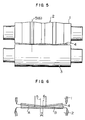
- Fig. 5 illustrates an examples of rolling for simultaneously obtaining a pair of deformed section steel strips each similar to that showed in Fig. 1 in which rolling a roll barrel of a rolling mill is effectively utilized to simultaneously provide two sets of deformed section in a steel strip.
- reference numerals 1 and 3 denote upper and lower working rolls for effecting the rolling to obtain the deformed section steel strip, respectively.
- Reference numeral 2 denotes a caliber provided on the upper roll 1
- reference numeral 4 denotes a material to be rolled.
- Japanese Patent Application No. 128880/1984 Japanese Unexamined Patent Publication No. 9911/1986
- a method of rolling by use of roll having caliber so as to produce a good steel strip of a deformed section having a large difference in thickness in the direction of the width thereof in which method a continuous hot rolling mill having one or a plurality of stands is used.
- This rolling method of producing a deformed section strip is characterized in that the strip is rolled under the following rolling condition for each stand: wherein Ch E is a thickness difference (mm) of a deformed section defined at the entrance side; h E is an average thickness (mm) thereof at the entrance side; Ch D is a thickness difference (mm) of another deformed section defined at the exit side; and h D is an average thickness (mm) thereof at the exit side.
- a bias occurring in another case of rolling a steel strip of deformed section having a thickness difference in the direction of width causes a position for engagement with rolls of a next stand to be deviated from a predetermined correct position, with the result that a difference in rolling reduction ratio occurs in the direction of the width of the steel strip with an elongation difference also occurring to cause an improper shape, so that in an extreme case it becomes impossible to effect the rolling due to the occurrence of defects such as bore or due to the occurrence of a phenomenon of chew up.
- Fig. 6 illustrates a main part of a strip and rolls at the time of occurrence of a biasing in this rolling process. In particular, when the strip is to be produced in a multiple-stage rolling manner, the influence of such biasing is more significant. In Fig.
- a reference numeral 5 indicates the center of a convex portion of the roll
- a reference numeral 6 indicating the center of a recessed portion of a rolled strip
- a reference numeral 7 indicating the extent of the bias regarding a strip.
- a reference symbol.A indicates an area of the strip at which area the strip is subjected to excessive rolling reduction
- a reference symbol B indicates an area where the strip is subjected to insufficient rolling reduction.
- a shape, an influence of the thickness difference at the entrance side of a rolling stand on the thickness difference at the exit side thereof and another influence of the depth of a caliber of a rolling stand on the thickness difference at the exit side have needed to be examined in detail.
- a first object of the present invention is to provide a method of producing a steel strip of deformed section in which method a strip is capable of being stably and optimally rolled by a caliber roll of each of multistage stands used to produce a steel strip of deformed section having a wide range of thickness difference in the direction of the width thereof, whereby such defects as described above in connection with the prior art are prevented from occurring regarding the contour of the deformed section steel strip.
- the method of the present invention provides a method comprising the steps of: providing an additional body portion at each side of a strip which is to be roiled into one or a plurality of steel strips of deformed section; and providing in a roll having a caliber a pair of hold portions each having a tilt face formed in connection with the caliber so that a self-aligning of the strip is obtained.
- a second object of the present invention is to provide a method of producing a steel strip of deformed section having a large thickness difference in a direction of width thereof, the method comprising the steps of: providing a formula capable of determining a limit of the thickness difference which can be provided in one stand with respect to both a shape and a heredity of the thickness difference; calculating both a number of stands necessary to effect rolling by use of caliber rolls and a depth of each caliber so that the aimed steel strip of deformed section is obtained with good results.
- the present invention provides a method which comprises, when producing a deformed section steel strip having a wide range of thickness difference in the direction of width by.using a continuous hot rolling mill, the steps of determining the number of necessary stands of rolling each applying a rolling-operation for providing a thickness difference in a rolled strip in accordance with both a degree of steepness concerning a thickness change occurring in the direction of width of the steel strip and a thickness difference in the steel strip, and effecting the rolling thereof by use of the rolling stands each having a roll of optimum caliber defined by the equation showed below.
- a degree of steepness is used to evaluate a shape of steel strip and is a percentage ratio of a height of a corrugation occurring in the rolling of a steel strip to a pitch of the corrugation.
- Equation (1) in the case of a deformed section steel strip, the symbols C h and C H are thickness difference in the direction of width, while in a case of a conventional flat plate the symbols C h and C H are values of strip crowns.
- Fig. 9 shows these regions.
- the crown heredity coefficient n used herein represents the rate of heredity of an entrance side strip crown, which rate is determined on the basis of the fact that the exit side thickness difference (the strip crown of a strip at the exit side) C h in the direction of width is created by both a partial heredity of the entrance thickness difference C H and a partial transfer of the roll-caliber depth C m .
- steps (1), (2) and (3) are in turn effected to determine the optimum number of caliber rolling stands and the optimum caliber depth at each stand so that a shape meeting a desired degree of steepness may be obtained with respect to a desired cross-sectional shape (average thickness, width and thickness difference).
- a deformed section steel strip is rolled through a hot strip mill by use of both the determined number of stands and the rolls for rolling determined in the manner described above.
- the rolling for producing a deformed section steel strip is effected in such a manner that a plurality of deformed section steel strips are simultaneously produced.
- Fig. 2 illustrates a case where two deformed section steel strips are obtained at the same time.
- reference numerals 8 and 8' denote excess metal portions formed in a rolled material
- reference numerals 9 and 9 1 denote hold portions of roll calibers. Since the rolling surfaces of the hold portions corresponding to the excess metal portions 8 and 8' which are in contact with the hold portions 9 and 9 at the time of rolling are slanted, the rolled material 4 receives from the roll at its both edges thereof reaction forces F and F' directed to the center of the rolled material 4. In a case where the rolled material 4 is biased in a direction, for example, to the right as viewed in Fig.
- the excess metal portion 8' excessively occupies the hold portion 9' at the side toward which the rolled material is biased, but the engagement of the excess metal portion 8 becomes insufficient with respect to the opposite hold portion 9. Also the width of a portion rolled by the hold portion 9' at the side toward which the rolled material is biased is increased, while the width at the opposite side is reduced. Therefore, the rolling reaction forces f and f' occurring at the hold portions and the reactions forces F and F' applied to the rolled material toward the center thereof are unbalanced, and the force is increased at the side toward which the rolled material is biased.
- the angle of inclination of the hold portions 9 and 9' will be described. If this inclination angle is not more than a tilt angle provided regarding the section of the rolled material 4, the hold portions will become insufficient with respect to the self-aligning function. Also, in a case where the excess metal portion is not to be used as a part a product, it is preferable to make a size of the excess metal portion smaller to increase a yield of a product, that is, it is preferable to make the width of the excess metal portion smaller and to make the inclination of the hold portion larger.
- the angle of the hold portion is set to be not less than 1° or not less than an angle of inclination of the cross-sectional shape of the rolled material.
- the relation between a width of the hold portion and a size of the excess metal portion is determined so that the former and the latter are made to equal to each other or so that the width of the excess metal portion is set to be slightly narrower than the width of the hold portion 9. This is necessary for preventing a part of the excess metal portion from being projected beyond the hold portion and for preventing this part from being rolled in a narrow roll gap defined by flat roll portions. Unless this condition is met, a local elongation occurs at the edge portion, unappropriate edge wave will occur.
- the width of the hold portion provided in a caliber roll is extremely small in comparison with the size of the excess metal portion, the excess metal portion will not sufficiently occupy a caliber portion, so that the reaction forces F and F' directed toward the center of the rolled material at the time of rolling are reduced. That is, the self-aligning function is reduced.
- the present invention provides the hold portions 9, 9' each comprising a tilted surface in a roll for rolling a deformed section steel strip, thereby enabling a self-aligning function brought about by a rolled material itself so as to substantially prevent any biasing of the strip and enabling a stable roll pass of the strip.
- This is particularly effective in a case where a steel material, which is to be continuously rolled into a deformed section steel strip by a plurality of stands of caliber rolls, is made to stably pass the caliber roll stands at a high speed.
- Fig. 3 shows the cutting of a deformed section steel strip provided with two deformed sections showed in Fig. 2, and a reference numeral 10 denotes portions cut out by a slitter or the like.
- the present invention can be applied to any cross-sectional shapes other than that showed in Fig. 1, for example, a section showed in Fig. 4 which is thin at its both sides and is thick at its center or other sections similar thereto.
- a steel material were rolled to have a form in which there are provided three deformed section portions to be slit into three strips. Therefore, the width of a product strip was 600 mm, and an excess metal portions of 30 mm in width were provided at each of the edges thereof when the material were rolled, with the result that a deformed section steel strip having a good, desired shape was produced.
- the rolling speed was the same value as that in the case of usual flat plate, and the rolling could be effected at a high speed.
- a deformed section steel strip having a width of 200 mm, average thickness of 2.6 mm, thickness difference of 0.8 mm and a degree of steepness not more than 2.5 % were produced by rolling through a hot strip mill having six finishing stands which were prepared as described below.
- optimal caliber rolling of a plurality of stands becomes possible by use of a hot strip mill, so that a mass production of a steel strip having an arbitrary thickness difference becomes possible.
Landscapes
- Engineering & Computer Science (AREA)
- Mechanical Engineering (AREA)
- Metal Rolling (AREA)
- Reduction Rolling/Reduction Stand/Operation Of Reduction Machine (AREA)
Applications Claiming Priority (4)
| Application Number | Priority Date | Filing Date | Title |
|---|---|---|---|
| JP57675/86 | 1986-03-15 | ||
| JP5767586A JPS62214803A (ja) | 1986-03-15 | 1986-03-15 | 異形断面鋼板の安定圧延方法 |
| JP5767686A JPS62214806A (ja) | 1986-03-15 | 1986-03-15 | ホツトストリツプミルによる異形断面鋼板の製造方法 |
| JP57676/86 | 1986-03-15 |
Publications (3)
| Publication Number | Publication Date |
|---|---|
| EP0264452A1 true EP0264452A1 (de) | 1988-04-27 |
| EP0264452A4 EP0264452A4 (de) | 1989-12-14 |
| EP0264452B1 EP0264452B1 (de) | 1992-07-01 |
Family
ID=26398739
Family Applications (1)
| Application Number | Title | Priority Date | Filing Date |
|---|---|---|---|
| EP87901680A Expired - Lifetime EP0264452B1 (de) | 1986-03-15 | 1987-03-13 | Verfahren zur herstellung von verformten stahlblechen in einer warmbandstrasse |
Country Status (4)
| Country | Link |
|---|---|
| US (1) | US4876874A (de) |
| EP (1) | EP0264452B1 (de) |
| DE (1) | DE3780116T2 (de) |
| WO (1) | WO1987005543A1 (de) |
Cited By (6)
| Publication number | Priority date | Publication date | Assignee | Title |
|---|---|---|---|---|
| RU2393932C1 (ru) * | 2009-04-08 | 2010-07-10 | Федеральное государственное образовательное учреждение высшего профессионального образования "Государственный технологический университет "Московский институт стали и сплавов" | Способ изготовления пластин для теплообменников |
| RU2455089C1 (ru) * | 2010-11-08 | 2012-07-10 | Общество с ограниченной ответственностью "Северсталь-Проект" | Способ производства стальных горячекатаных полос |
| CN102581028A (zh) * | 2012-03-06 | 2012-07-18 | 太原理工大学 | 一种控制带钢热轧成型工艺的硬度补偿方法 |
| RU2482930C1 (ru) * | 2012-03-30 | 2013-05-27 | Федеральное государственное автономное образовательное учреждение высшего профессионального образования "Национальный исследовательский технологический университет "МИСиС" | Способ производства полос с односторонним чечевичным рифлением |
| CN103192266A (zh) * | 2013-04-03 | 2013-07-10 | 哈尔滨理工大学 | 带筋整体壁板挤轧复合成形装置及方法 |
| CN103831297A (zh) * | 2014-03-05 | 2014-06-04 | 东北大学 | 横向局部加厚板带材及其制备方法 |
Families Citing this family (2)
| Publication number | Priority date | Publication date | Assignee | Title |
|---|---|---|---|---|
| JP2544682B2 (ja) * | 1990-10-04 | 1996-10-16 | 同和鉱業株式会社 | 異形条材の製造方法 |
| CN116550945B (zh) * | 2022-01-27 | 2025-08-05 | 有研金属复合材料(北京)股份公司 | 连续浇注法生产铜钢双金属轴瓦材料的板形控制方法 |
Family Cites Families (12)
| Publication number | Priority date | Publication date | Assignee | Title |
|---|---|---|---|---|
| JPS55106601A (en) * | 1979-01-11 | 1980-08-15 | Nippon Kokan Kk <Nkk> | Manufacture of slab for thick steel plate by continuous casting |
| JPS6012122B2 (ja) * | 1980-09-17 | 1985-03-30 | 住友金属工業株式会社 | ホツト・ストリツプ・ミルにおけるクロツプ改善方法 |
| SU1034800A1 (ru) * | 1981-04-08 | 1983-08-15 | Уральский ордена Трудового Красного Знамени политехнический институт им.С.М.Кирова | Валковый узел |
| JPS586708A (ja) * | 1981-07-02 | 1983-01-14 | Kawasaki Steel Corp | エツジヤロ−ル |
| ZA837266B (en) * | 1982-10-26 | 1984-05-30 | Kennecott Corp | Hot mill self-centering roll design |
| SU1119748A1 (ru) * | 1983-07-22 | 1984-10-23 | Запорожский индустриальный институт | Прокатный валок |
| JPS59209409A (ja) * | 1984-04-18 | 1984-11-28 | Ishikawajima Harima Heavy Ind Co Ltd | 圧延機 |
| JPS60255209A (ja) * | 1984-05-30 | 1985-12-16 | Mitsubishi Heavy Ind Ltd | 圧延機におけるエツジヤ開度制御方法 |
| US4531270A (en) * | 1984-06-13 | 1985-07-30 | United Technologies Corporation | Method for the manufacture of metal vanes for turbomachinery |
| JPS619911A (ja) * | 1984-06-22 | 1986-01-17 | Nippon Steel Corp | 異形断面ストリツプの圧延方法 |
| JPS61144202A (ja) * | 1984-12-19 | 1986-07-01 | Kawasaki Steel Corp | 板材の形状制御圧延方法および圧延機 |
| US4730475A (en) * | 1986-05-06 | 1988-03-15 | International Rolling Mills Consultants, Inc. | Rolling mill method |
-
1987
- 1987-03-12 US US07/128,112 patent/US4876874A/en not_active Expired - Fee Related
- 1987-03-13 WO PCT/JP1987/000158 patent/WO1987005543A1/ja not_active Ceased
- 1987-03-13 EP EP87901680A patent/EP0264452B1/de not_active Expired - Lifetime
- 1987-03-13 DE DE8787901680T patent/DE3780116T2/de not_active Expired - Fee Related
Cited By (9)
| Publication number | Priority date | Publication date | Assignee | Title |
|---|---|---|---|---|
| RU2393932C1 (ru) * | 2009-04-08 | 2010-07-10 | Федеральное государственное образовательное учреждение высшего профессионального образования "Государственный технологический университет "Московский институт стали и сплавов" | Способ изготовления пластин для теплообменников |
| RU2455089C1 (ru) * | 2010-11-08 | 2012-07-10 | Общество с ограниченной ответственностью "Северсталь-Проект" | Способ производства стальных горячекатаных полос |
| CN102581028A (zh) * | 2012-03-06 | 2012-07-18 | 太原理工大学 | 一种控制带钢热轧成型工艺的硬度补偿方法 |
| CN102581028B (zh) * | 2012-03-06 | 2013-11-13 | 太原理工大学 | 一种控制带钢热轧成型工艺的硬度补偿方法 |
| RU2482930C1 (ru) * | 2012-03-30 | 2013-05-27 | Федеральное государственное автономное образовательное учреждение высшего профессионального образования "Национальный исследовательский технологический университет "МИСиС" | Способ производства полос с односторонним чечевичным рифлением |
| CN103192266A (zh) * | 2013-04-03 | 2013-07-10 | 哈尔滨理工大学 | 带筋整体壁板挤轧复合成形装置及方法 |
| CN103192266B (zh) * | 2013-04-03 | 2016-01-13 | 哈尔滨理工大学 | 带筋整体壁板挤轧复合成形装置及方法 |
| CN103831297A (zh) * | 2014-03-05 | 2014-06-04 | 东北大学 | 横向局部加厚板带材及其制备方法 |
| CN103831297B (zh) * | 2014-03-05 | 2015-09-30 | 东北大学 | 横向局部加厚板带材及其制备方法 |
Also Published As
| Publication number | Publication date |
|---|---|
| DE3780116D1 (de) | 1992-08-06 |
| EP0264452B1 (de) | 1992-07-01 |
| EP0264452A4 (de) | 1989-12-14 |
| WO1987005543A1 (fr) | 1987-09-24 |
| US4876874A (en) | 1989-10-31 |
| DE3780116T2 (de) | 1993-02-18 |
Similar Documents
| Publication | Publication Date | Title |
|---|---|---|
| EP0264452B1 (de) | Verfahren zur herstellung von verformten stahlblechen in einer warmbandstrasse | |
| EP0142568B1 (de) | Verfahren und vorrichtung für rollende radkranzsektion | |
| US5115660A (en) | Method for making band plates deformed in section | |
| EP0348913B1 (de) | Verfahren zum Walzen von Doppel-T-Stahlprofilen | |
| KR900009128B1 (ko) | 열연 방법 | |
| EP0644001B1 (de) | Verfahren zum kaltwalzen von metallischem bandmaterial | |
| US4856313A (en) | Method of controlling strip crown in planetary rolling | |
| Saito et al. | Development of satellite mill and trial rolling of profiled metal strip | |
| JP2926170B2 (ja) | アングル材の製造方法 | |
| SU984522A1 (ru) | Рабочий валок листопрокатной клети | |
| CA1114658A (en) | Method for producing beam blank for large size h-beam from flat slab | |
| JP4454441B2 (ja) | 異形断面帯材の断面矯正方法 | |
| JP2003285112A (ja) | チタン板の冷間圧延方法 | |
| US3866451A (en) | Method for producing multiple gauge strip | |
| SU1328016A1 (ru) | Рабочий валок черновой листопрокатной клети | |
| SU984516A1 (ru) | Способ получени подката дл чистовой клети листового стана | |
| JPH0679387A (ja) | 異形断面をもつ条材の製造方法及び溝付き成形ロール | |
| EP0760263A1 (de) | Verfahren und vorrichtung zum warmwalzen von h-stahlträgern | |
| JPS62214803A (ja) | 異形断面鋼板の安定圧延方法 | |
| JP4089543B2 (ja) | 狭フランジ幅h形鋼のユニバーサル圧延方法 | |
| JPH0550105A (ja) | 異形断面帯板の製造方法 | |
| CA1302743C (en) | Method of controlling strip crown in planetary rolling | |
| SU971541A1 (ru) | Валковый узел прокатного стана | |
| EP0199017A2 (de) | Ausgleich der Spannung bei Bandmaterial | |
| JPWO1995017269A1 (ja) | H形鋼の製造方法 |
Legal Events
| Date | Code | Title | Description |
|---|---|---|---|
| PUAI | Public reference made under article 153(3) epc to a published international application that has entered the european phase |
Free format text: ORIGINAL CODE: 0009012 |
|
| 17P | Request for examination filed |
Effective date: 19871126 |
|
| AK | Designated contracting states |
Kind code of ref document: A1 Designated state(s): DE FR GB |
|
| A4 | Supplementary search report drawn up and despatched |
Effective date: 19891214 |
|
| 17Q | First examination report despatched |
Effective date: 19901210 |
|
| GRAA | (expected) grant |
Free format text: ORIGINAL CODE: 0009210 |
|
| AK | Designated contracting states |
Kind code of ref document: B1 Designated state(s): DE FR GB |
|
| REF | Corresponds to: |
Ref document number: 3780116 Country of ref document: DE Date of ref document: 19920806 |
|
| ET | Fr: translation filed | ||
| PLBE | No opposition filed within time limit |
Free format text: ORIGINAL CODE: 0009261 |
|
| STAA | Information on the status of an ep patent application or granted ep patent |
Free format text: STATUS: NO OPPOSITION FILED WITHIN TIME LIMIT |
|
| 26N | No opposition filed | ||
| PGFP | Annual fee paid to national office [announced via postgrant information from national office to epo] |
Ref country code: FR Payment date: 19960126 Year of fee payment: 10 |
|
| PGFP | Annual fee paid to national office [announced via postgrant information from national office to epo] |
Ref country code: GB Payment date: 19960304 Year of fee payment: 10 |
|
| PGFP | Annual fee paid to national office [announced via postgrant information from national office to epo] |
Ref country code: DE Payment date: 19960313 Year of fee payment: 10 |
|
| PG25 | Lapsed in a contracting state [announced via postgrant information from national office to epo] |
Ref country code: GB Effective date: 19970313 |
|
| GBPC | Gb: european patent ceased through non-payment of renewal fee |
Effective date: 19970313 |
|
| PG25 | Lapsed in a contracting state [announced via postgrant information from national office to epo] |
Ref country code: FR Free format text: LAPSE BECAUSE OF NON-PAYMENT OF DUE FEES Effective date: 19971128 |
|
| PG25 | Lapsed in a contracting state [announced via postgrant information from national office to epo] |
Ref country code: DE Effective date: 19971202 |
|
| REG | Reference to a national code |
Ref country code: FR Ref legal event code: ST |