EP0264523B1 - Méthode de séparation d'un mélange gazeux - Google Patents
Méthode de séparation d'un mélange gazeux Download PDFInfo
- Publication number
- EP0264523B1 EP0264523B1 EP87103169A EP87103169A EP0264523B1 EP 0264523 B1 EP0264523 B1 EP 0264523B1 EP 87103169 A EP87103169 A EP 87103169A EP 87103169 A EP87103169 A EP 87103169A EP 0264523 B1 EP0264523 B1 EP 0264523B1
- Authority
- EP
- European Patent Office
- Prior art keywords
- gas
- porous body
- gaseous mixture
- adsorption
- pressure
- Prior art date
- Legal status (The legal status is an assumption and is not a legal conclusion. Google has not performed a legal analysis and makes no representation as to the accuracy of the status listed.)
- Expired - Lifetime
Links
Images


Classifications
-
- B—PERFORMING OPERATIONS; TRANSPORTING
- B01—PHYSICAL OR CHEMICAL PROCESSES OR APPARATUS IN GENERAL
- B01D—SEPARATION
- B01D53/00—Separation of gases or vapours; Recovering vapours of volatile solvents from gases; Chemical or biological purification of waste gases, e.g. engine exhaust gases, smoke, fumes, flue gases, aerosols
- B01D53/02—Separation of gases or vapours; Recovering vapours of volatile solvents from gases; Chemical or biological purification of waste gases, e.g. engine exhaust gases, smoke, fumes, flue gases, aerosols by adsorption, e.g. preparative gas chromatography
- B01D53/04—Separation of gases or vapours; Recovering vapours of volatile solvents from gases; Chemical or biological purification of waste gases, e.g. engine exhaust gases, smoke, fumes, flue gases, aerosols by adsorption, e.g. preparative gas chromatography with stationary adsorbents
- B01D53/047—Pressure swing adsorption
-
- B—PERFORMING OPERATIONS; TRANSPORTING
- B01—PHYSICAL OR CHEMICAL PROCESSES OR APPARATUS IN GENERAL
- B01J—CHEMICAL OR PHYSICAL PROCESSES, e.g. CATALYSIS OR COLLOID CHEMISTRY; THEIR RELEVANT APPARATUS
- B01J20/00—Solid sorbent compositions or filter aid compositions; Sorbents for chromatography; Processes for preparing, regenerating or reactivating thereof
- B01J20/02—Solid sorbent compositions or filter aid compositions; Sorbents for chromatography; Processes for preparing, regenerating or reactivating thereof comprising inorganic material
- B01J20/20—Solid sorbent compositions or filter aid compositions; Sorbents for chromatography; Processes for preparing, regenerating or reactivating thereof comprising inorganic material comprising free carbon; comprising carbon obtained by carbonising processes
-
- B—PERFORMING OPERATIONS; TRANSPORTING
- B01—PHYSICAL OR CHEMICAL PROCESSES OR APPARATUS IN GENERAL
- B01D—SEPARATION
- B01D2253/00—Adsorbents used in seperation treatment of gases and vapours
- B01D2253/10—Inorganic adsorbents
- B01D2253/102—Carbon
-
- B—PERFORMING OPERATIONS; TRANSPORTING
- B01—PHYSICAL OR CHEMICAL PROCESSES OR APPARATUS IN GENERAL
- B01D—SEPARATION
- B01D2253/00—Adsorbents used in seperation treatment of gases and vapours
- B01D2253/25—Coated, impregnated or composite adsorbents
-
- B—PERFORMING OPERATIONS; TRANSPORTING
- B01—PHYSICAL OR CHEMICAL PROCESSES OR APPARATUS IN GENERAL
- B01D—SEPARATION
- B01D2253/00—Adsorbents used in seperation treatment of gases and vapours
- B01D2253/30—Physical properties of adsorbents
- B01D2253/302—Dimensions
- B01D2253/306—Surface area, e.g. BET-specific surface
-
- B—PERFORMING OPERATIONS; TRANSPORTING
- B01—PHYSICAL OR CHEMICAL PROCESSES OR APPARATUS IN GENERAL
- B01D—SEPARATION
- B01D2253/00—Adsorbents used in seperation treatment of gases and vapours
- B01D2253/30—Physical properties of adsorbents
- B01D2253/302—Dimensions
- B01D2253/308—Pore size
-
- B—PERFORMING OPERATIONS; TRANSPORTING
- B01—PHYSICAL OR CHEMICAL PROCESSES OR APPARATUS IN GENERAL
- B01D—SEPARATION
- B01D2253/00—Adsorbents used in seperation treatment of gases and vapours
- B01D2253/30—Physical properties of adsorbents
- B01D2253/302—Dimensions
- B01D2253/31—Pore size distribution
-
- B—PERFORMING OPERATIONS; TRANSPORTING
- B01—PHYSICAL OR CHEMICAL PROCESSES OR APPARATUS IN GENERAL
- B01D—SEPARATION
- B01D2253/00—Adsorbents used in seperation treatment of gases and vapours
- B01D2253/30—Physical properties of adsorbents
- B01D2253/302—Dimensions
- B01D2253/311—Porosity, e.g. pore volume
-
- B—PERFORMING OPERATIONS; TRANSPORTING
- B01—PHYSICAL OR CHEMICAL PROCESSES OR APPARATUS IN GENERAL
- B01D—SEPARATION
- B01D2253/00—Adsorbents used in seperation treatment of gases and vapours
- B01D2253/30—Physical properties of adsorbents
- B01D2253/34—Specific shapes
-
- B—PERFORMING OPERATIONS; TRANSPORTING
- B01—PHYSICAL OR CHEMICAL PROCESSES OR APPARATUS IN GENERAL
- B01D—SEPARATION
- B01D2256/00—Main component in the product gas stream after treatment
- B01D2256/10—Nitrogen
-
- B—PERFORMING OPERATIONS; TRANSPORTING
- B01—PHYSICAL OR CHEMICAL PROCESSES OR APPARATUS IN GENERAL
- B01D—SEPARATION
- B01D2256/00—Main component in the product gas stream after treatment
- B01D2256/16—Hydrogen
-
- B—PERFORMING OPERATIONS; TRANSPORTING
- B01—PHYSICAL OR CHEMICAL PROCESSES OR APPARATUS IN GENERAL
- B01D—SEPARATION
- B01D2256/00—Main component in the product gas stream after treatment
- B01D2256/20—Carbon monoxide
-
- B—PERFORMING OPERATIONS; TRANSPORTING
- B01—PHYSICAL OR CHEMICAL PROCESSES OR APPARATUS IN GENERAL
- B01D—SEPARATION
- B01D2257/00—Components to be removed
- B01D2257/10—Single element gases other than halogens
- B01D2257/104—Oxygen
-
- B—PERFORMING OPERATIONS; TRANSPORTING
- B01—PHYSICAL OR CHEMICAL PROCESSES OR APPARATUS IN GENERAL
- B01D—SEPARATION
- B01D2257/00—Components to be removed
- B01D2257/50—Carbon oxides
- B01D2257/504—Carbon dioxide
-
- B—PERFORMING OPERATIONS; TRANSPORTING
- B01—PHYSICAL OR CHEMICAL PROCESSES OR APPARATUS IN GENERAL
- B01D—SEPARATION
- B01D2257/00—Components to be removed
- B01D2257/70—Organic compounds not provided for in groups B01D2257/00 - B01D2257/602
- B01D2257/702—Hydrocarbons
- B01D2257/7022—Aliphatic hydrocarbons
- B01D2257/7025—Methane
-
- B—PERFORMING OPERATIONS; TRANSPORTING
- B01—PHYSICAL OR CHEMICAL PROCESSES OR APPARATUS IN GENERAL
- B01D—SEPARATION
- B01D2259/00—Type of treatment
- B01D2259/40—Further details for adsorption processes and devices
- B01D2259/40011—Methods relating to the process cycle in pressure or temperature swing adsorption
- B01D2259/40028—Depressurization
- B01D2259/4003—Depressurization with two sub-steps
-
- B—PERFORMING OPERATIONS; TRANSPORTING
- B01—PHYSICAL OR CHEMICAL PROCESSES OR APPARATUS IN GENERAL
- B01D—SEPARATION
- B01D2259/00—Type of treatment
- B01D2259/40—Further details for adsorption processes and devices
- B01D2259/40011—Methods relating to the process cycle in pressure or temperature swing adsorption
- B01D2259/40035—Equalization
- B01D2259/40037—Equalization with two sub-steps
-
- B—PERFORMING OPERATIONS; TRANSPORTING
- B01—PHYSICAL OR CHEMICAL PROCESSES OR APPARATUS IN GENERAL
- B01D—SEPARATION
- B01D2259/00—Type of treatment
- B01D2259/40—Further details for adsorption processes and devices
- B01D2259/40011—Methods relating to the process cycle in pressure or temperature swing adsorption
- B01D2259/40043—Purging
- B01D2259/4005—Nature of purge gas
- B01D2259/40052—Recycled product or process gas
-
- B—PERFORMING OPERATIONS; TRANSPORTING
- B01—PHYSICAL OR CHEMICAL PROCESSES OR APPARATUS IN GENERAL
- B01D—SEPARATION
- B01D2259/00—Type of treatment
- B01D2259/40—Further details for adsorption processes and devices
- B01D2259/40011—Methods relating to the process cycle in pressure or temperature swing adsorption
- B01D2259/40058—Number of sequence steps, including sub-steps, per cycle
- B01D2259/4006—Less than four
-
- B—PERFORMING OPERATIONS; TRANSPORTING
- B01—PHYSICAL OR CHEMICAL PROCESSES OR APPARATUS IN GENERAL
- B01D—SEPARATION
- B01D2259/00—Type of treatment
- B01D2259/40—Further details for adsorption processes and devices
- B01D2259/40011—Methods relating to the process cycle in pressure or temperature swing adsorption
- B01D2259/40058—Number of sequence steps, including sub-steps, per cycle
- B01D2259/40062—Four
-
- B—PERFORMING OPERATIONS; TRANSPORTING
- B01—PHYSICAL OR CHEMICAL PROCESSES OR APPARATUS IN GENERAL
- B01D—SEPARATION
- B01D2259/00—Type of treatment
- B01D2259/40—Further details for adsorption processes and devices
- B01D2259/40011—Methods relating to the process cycle in pressure or temperature swing adsorption
- B01D2259/40058—Number of sequence steps, including sub-steps, per cycle
- B01D2259/40064—Five
-
- B—PERFORMING OPERATIONS; TRANSPORTING
- B01—PHYSICAL OR CHEMICAL PROCESSES OR APPARATUS IN GENERAL
- B01D—SEPARATION
- B01D2259/00—Type of treatment
- B01D2259/40—Further details for adsorption processes and devices
- B01D2259/40011—Methods relating to the process cycle in pressure or temperature swing adsorption
- B01D2259/40077—Direction of flow
- B01D2259/40081—Counter-current
-
- B—PERFORMING OPERATIONS; TRANSPORTING
- B01—PHYSICAL OR CHEMICAL PROCESSES OR APPARATUS IN GENERAL
- B01D—SEPARATION
- B01D2259/00—Type of treatment
- B01D2259/40—Further details for adsorption processes and devices
- B01D2259/401—Further details for adsorption processes and devices using a single bed
-
- B—PERFORMING OPERATIONS; TRANSPORTING
- B01—PHYSICAL OR CHEMICAL PROCESSES OR APPARATUS IN GENERAL
- B01D—SEPARATION
- B01D2259/00—Type of treatment
- B01D2259/40—Further details for adsorption processes and devices
- B01D2259/402—Further details for adsorption processes and devices using two beds
-
- B—PERFORMING OPERATIONS; TRANSPORTING
- B01—PHYSICAL OR CHEMICAL PROCESSES OR APPARATUS IN GENERAL
- B01D—SEPARATION
- B01D2259/00—Type of treatment
- B01D2259/40—Further details for adsorption processes and devices
- B01D2259/404—Further details for adsorption processes and devices using four beds
-
- B—PERFORMING OPERATIONS; TRANSPORTING
- B01—PHYSICAL OR CHEMICAL PROCESSES OR APPARATUS IN GENERAL
- B01D—SEPARATION
- B01D53/00—Separation of gases or vapours; Recovering vapours of volatile solvents from gases; Chemical or biological purification of waste gases, e.g. engine exhaust gases, smoke, fumes, flue gases, aerosols
- B01D53/02—Separation of gases or vapours; Recovering vapours of volatile solvents from gases; Chemical or biological purification of waste gases, e.g. engine exhaust gases, smoke, fumes, flue gases, aerosols by adsorption, e.g. preparative gas chromatography
- B01D53/04—Separation of gases or vapours; Recovering vapours of volatile solvents from gases; Chemical or biological purification of waste gases, e.g. engine exhaust gases, smoke, fumes, flue gases, aerosols by adsorption, e.g. preparative gas chromatography with stationary adsorbents
- B01D53/0407—Constructional details of adsorbing systems
- B01D53/0431—Beds with radial gas flow
-
- B—PERFORMING OPERATIONS; TRANSPORTING
- B01—PHYSICAL OR CHEMICAL PROCESSES OR APPARATUS IN GENERAL
- B01D—SEPARATION
- B01D53/00—Separation of gases or vapours; Recovering vapours of volatile solvents from gases; Chemical or biological purification of waste gases, e.g. engine exhaust gases, smoke, fumes, flue gases, aerosols
- B01D53/02—Separation of gases or vapours; Recovering vapours of volatile solvents from gases; Chemical or biological purification of waste gases, e.g. engine exhaust gases, smoke, fumes, flue gases, aerosols by adsorption, e.g. preparative gas chromatography
- B01D53/04—Separation of gases or vapours; Recovering vapours of volatile solvents from gases; Chemical or biological purification of waste gases, e.g. engine exhaust gases, smoke, fumes, flue gases, aerosols by adsorption, e.g. preparative gas chromatography with stationary adsorbents
- B01D53/047—Pressure swing adsorption
- B01D53/0473—Rapid pressure swing adsorption
-
- Y—GENERAL TAGGING OF NEW TECHNOLOGICAL DEVELOPMENTS; GENERAL TAGGING OF CROSS-SECTIONAL TECHNOLOGIES SPANNING OVER SEVERAL SECTIONS OF THE IPC; TECHNICAL SUBJECTS COVERED BY FORMER USPC CROSS-REFERENCE ART COLLECTIONS [XRACs] AND DIGESTS
- Y02—TECHNOLOGIES OR APPLICATIONS FOR MITIGATION OR ADAPTATION AGAINST CLIMATE CHANGE
- Y02C—CAPTURE, STORAGE, SEQUESTRATION OR DISPOSAL OF GREENHOUSE GASES [GHG]
- Y02C20/00—Capture or disposal of greenhouse gases
- Y02C20/20—Capture or disposal of greenhouse gases of methane
-
- Y—GENERAL TAGGING OF NEW TECHNOLOGICAL DEVELOPMENTS; GENERAL TAGGING OF CROSS-SECTIONAL TECHNOLOGIES SPANNING OVER SEVERAL SECTIONS OF THE IPC; TECHNICAL SUBJECTS COVERED BY FORMER USPC CROSS-REFERENCE ART COLLECTIONS [XRACs] AND DIGESTS
- Y02—TECHNOLOGIES OR APPLICATIONS FOR MITIGATION OR ADAPTATION AGAINST CLIMATE CHANGE
- Y02C—CAPTURE, STORAGE, SEQUESTRATION OR DISPOSAL OF GREENHOUSE GASES [GHG]
- Y02C20/00—Capture or disposal of greenhouse gases
- Y02C20/40—Capture or disposal of greenhouse gases of CO2
-
- Y—GENERAL TAGGING OF NEW TECHNOLOGICAL DEVELOPMENTS; GENERAL TAGGING OF CROSS-SECTIONAL TECHNOLOGIES SPANNING OVER SEVERAL SECTIONS OF THE IPC; TECHNICAL SUBJECTS COVERED BY FORMER USPC CROSS-REFERENCE ART COLLECTIONS [XRACs] AND DIGESTS
- Y10—TECHNICAL SUBJECTS COVERED BY FORMER USPC
- Y10S—TECHNICAL SUBJECTS COVERED BY FORMER USPC CROSS-REFERENCE ART COLLECTIONS [XRACs] AND DIGESTS
- Y10S95/00—Gas separation: processes
- Y10S95/90—Solid sorbent
- Y10S95/902—Molecular sieve
- Y10S95/903—Carbon
Definitions
- This invention relates to a method of separating a gaseous mixture, and more specifically, to a method of separating a mixture of at least two gases having different chemical compositions by physical adsorption.
- This device was built by applying a pressure swing adsorption method (to be abbreviated as the PSA method) which comprises feeding air as a raw material under pressure into an adsorption tower packed with an adsorbent having a molecular sieving effect, such as granular molecular sieving carbon (MSC, a product of Bergbaumaschine), to adsorb oxygen selectively on the adsorbent and thus produce a gas rich in nitrogen (see Japanese Patent Publication No 17595/1969 and British Patent No 1480866). Nitrogen gas is obtained as a non-adsorbing component, and by desorbing the gas adsorbed on the adsorbent, a gas rich in oxygen can be produced.
- a pressure swing adsorption method to be abbreviated as the PSA method
- MSC granular molecular sieving carbon
- the device utilizing the PSA method has come into use in place of the low temperature liquefying separation device because it is relatively small in size and is convenient to operate and can be continuously operated without an operator.
- a device having a capacity of about 50 to 1000 Nm3/H has the advantage that the unit power cost is lower than that of the low temperature liquefying separation device and the product gas becomes lower in price.
- a device having a capacity of less than about 50 Nm3/H is economically very inferior because the unit power cost is very high.
- MSC molecular sieving carbon
- the present inventors studied the mechanism of adsorption and desorption of the MSC (usually in the form of a small solid cylinder having a diameter of 2 to 4 mm and a length of 3 to 5 mm) by taking its photograph through a scanning electron microscope.
- This study led to the following discovery.
- a relatively large pore (macropore) 101 for the inflow of the starting air is formed on the surface of MSC as schematically shown in Figure 6, and on the wall surface of the macropore 101, micropores 102 having a molecular sieving action are distributed to form a two-stage pore structure.
- the starting air comes into the macropore 101 from its opening 101a where oxygen is selectively adsorbed. Then, the air turns and flows reversely in the macropore 101, and goes out of it from the opening 101a. The air is separated by this flow of the starting air.
- the starting air passes through the spaces between MSC chip and enters the macropore 101 of each of the individual MSC chips where oxygen is selectively adsorbed. The remainder goes out from the macropores, and again enters the next macropore 101 where oxygen is selectively adsorbed. This action is repeated, and the remainder of the starting air is led out of the adsorption tower through the spaces among the MSC particles.
- FIG. 7 of the accompanying drawings is a scanning electronmicrograph (magnification 100) of the above granular MSC.
- the relatively large hole-like portions seen in the micrograph are the opening portions of macropores.
- Japanese Laid-Open Patent Publication No. 6108/1986 discloses molecular sieving carbon having the maximum value of the pore diameter distribution in a region not more than 10 ⁇ 10 ⁇ 10m and a pore volume of not more than 0.1 cm3/g in a pore diameter range of 15 to 200 ⁇ 10 ⁇ 10m which is produced from a mixture of a phenolic resin and a polyvinyl alcohol resin.
- This molecular sieving carbon is one of those adsorbents which have a high adsorption volume and a high speed of adsorption and desorption.
- EP-A-0 015 115 discloses partially pyrolyzed polymer particles which can be used to adsorb liquids or gases.
- Another object of this invention is to provide a method of efficiently separating at least a first gas by physical adsorption from a gaseous mixture, for example air, containing the first gas and a second gas having different chemical compositions, such as nitrogen and oxygen, in an amount of at least 50% by volume based on the entire mixture.
- a gaseous mixture for example air
- a second gas having different chemical compositions, such as nitrogen and oxygen
- Still another object of this invention is to provide a method of efficiently separating a gaseous mixture using an adsorbent having a high volume of adsorption and high speeds of absorption and desorption, in which the adsorbing and desorbing ability of the adsorbent is utilized to a maximum.
- Yet another object of this invention is to provide a method of efficiently obtaining a desired gas by subjecting a gaseous mixture to bulk separation by a pressure swing adsorption method.
- a method of separating at least a first gas from a gaseous mixture which comprises contacting a gaseous mixture containing a first and a second gas having different chemical compositions in an amount of at least 50% by volume based on the entire mixture with a molecular sieving carbonaceous porous body, said porous body having (1) a carbon content of at least 85 % by weight, (2) an apparent density of 0.1 to 0.8 g/cm3, (3) a porosity of 50 to 95 %, (4) a maximum value of the pore diameter distribution at a pore diameter of not more than 10 ⁇ 10 ⁇ 10m and a pore volume at a pore diameter in the range of 15 to 200 ⁇ 10 ⁇ 10m of not more than 0.1 cm3/g and containing (5) open cells having an average diameter of 1 to 500 micrometers.
- the gaseous mixture which is to be separated by the method of this invention contains two gases (the first and second gases) in a proportion of at least 50% by volume, preferably at least 75% by volume, more preferably at least 90% by volume, based on the total volume of the gaseous mixture.
- the volume percents herein are based on the volumes in a standard condition, namely at 0°C and 1 bar (atmosphere).
- gaseous mixtures containing hydrogen and methane as main components such as an ethylene plant offgas and a coke furnace offgas
- gaseous mixtures containing hydrogen and carbon dioxide as main components such as methanol reformed gas generated by reaction of methanol with steam and steam reforming gas
- gaseous mixtures containing carbon monoxide and methane as main components such as a gaseous mixture obtained by separating hydrogen gas from a coke furnace offgas
- gaseous mixtures containing hydrogen and carbon monoxide as main components such as a gaseous mixture resulting from decomposition of methanol
- gaseous mixtures containing nitrogen and carbon monoxide as main components such as a converter offgas
- gaseous mixtures containing nitrogen and oxygen as main components such as air.
- the ethylene plant offgas typically contains 94 to 96% of hydrogen and 4 to 6% of methane and minor amounts of ethane, ethylene, nitrogen, etc.
- the coke furnace offgas contains 55 to 57% of hydrogen, 26 to 27% of methane, 6 to 7% of carbon monoxide and 2 to 3% of carbon dioxide.
- the methanol reformed gas contains about 75% of hydrogen and about 24% of carbon dioxide as main components and minor amounts of carbon monoxide, methane, etc.
- the adsorbent used in this invention contains at least 85% by weight, preferably at least 90% by weight, of carbon.
- the upper limit of the carbon content substantially reaches 100%, and is usually about 98%.
- Elements contained in addition to carbon are usually oxygen, hydrogen and nitrogen.
- the adsorbent used in this invention is a carbonaceous porous body containing open cells in a three-dimensional network structure. These open cells constitute substantial flow passages for the gaseous mixture to be separated.
- the average pore diameter of the open pores is preferably 1 to 500 micrometers, more preferably 10 to 300 micrometers.
- the carbonaceous porous body has an apparent density of 0.1 to 0.8 g/cm3, preferably 0.3 to 0.65 g/cm3, and a porosity of 50 to 95%, preferably 60 to 82%.
- the carbonaceous porous body used in this invention may be prepared from polyvinyl alcohol, a melamine resin and a phenol resin by, for example, preparing a porous body of a synthetic resin from 10 to 50% by weight of polyvinyl alcohol, 10 to 40% by weight of the melamine resin and 80 to 70% by weight of the phenolic resin, and carbonizing the porous body in a non-oxidizing atmosphere at a temperature of 500 to 700°C.
- the resulting carbonized product can be directly used as the carbonaceous porous body in this invention. If desired, it is used after activating it by heat-treating it in an oxidizing atmosphere at a temperature of 500 to 700°C within the weight loss of the carbonized product being up to 15% by weight.
- Polyvinyl alcohol may be used as such or as a polyvinyl acetal resin such as polyvinyl formal or polyvinyl benzal obtained by acetalization of polyvinyl alcohol.
- the melamine resin is an initial-stage condensate of melamine and formaldehyde usually having solubility in water.
- a resol resin or novolak resin in solution form can be conveniently used as the phenolic resin.
- Production of the porous body of synthetic resin from the polyvinyl alcohol, melamine resin and phenolic resin is carried out by adding a pore-forming material such as starch, a modified starch, a starch derivative or a water-soluble metal salt to these raw materials in any desired step of specific methods described below in accordance with the methods described in, for example, Japanese Patent Publication No. 54082/1983, Japanese Laid-Open Patent Publication No. 51109/1982, and Japanese Patent Publication No. 31052/1985.
- a plastic porous body containing open-cellular macropores in a network structure can be produced.
- Examples of the specific methods include a method which comprises reacting polyvinyl alcohol with a crosslinking agent in the presence of a curing catalyst to produce a polyvinyl acetal resin such as polyvinyl formal or polyvinyl benzal, and applying predetermined amounts of the melamine resin and the phenolic resin to the acetal resin by such means as impregnation; a method which comprises uniformly mixing polyvinyl alcohol with a liquid melamine resin or a liquid phenolic resin, adding a cross-linking agent and a curing agent or a curing catalyst, copolymerizing the above mixture, and then applying the remaining one resin to the copolymer; and a method which comprises uniformly mixing polyvinyl alcohol, a liquid melamine resin and a liquid phenolic resin, adding a crosslinking agent and a curing agent or a curing catalyst, and copolymerizing the above mixture.
- crosslinking agent such as formaldehyde and benzaldehyde are suitable as crosslinking agents for polyvinyl alcohol.
- Suitable catalysts for the acetalization reaction of polyvinyl alcohol and the curing reaction of the phenolic resin are hydrochloric acid, sulfuric acid, oxalic acid, lactic acid, p-toluenesulfonic acid, maleic acid and malonic acid.
- Suitable curing agents for the melamine resin include inorganic acids such as hydrochloric acid and sulfuric acid, carboxylic acid esters such as dimethyl oxalate, and amine hydrochlorides such as ethylamine hydrochloride and triethanolamine hydrochloride.
- a preferred combination of the raw materials comprises 15 to 40% by weight of polyvinyl alcohol, 15 to 30% by weight of the melamine resin and 40 to 65% by weight of the phenolic resin.
- a more preferred combination comprises 20 to 30% by weight of polyvinyl alcohol, 15 to 25% by weight of the melamine resin and 45 to 60% by weight of the phenolic resin.
- the weight percentages of the raw materials are based on the total weight of the polyvinyl alcohol, melamine resin and phenolic resin.
- the carbonaceous porous body used in this invention is obtained by carbonizing the resulting porous body of synthetic resin in a non-oxidizing atmosphere at a temperature of 500 to 700°C.
- micropore volume and pore radius of the micropores are measured by analysis using a nitrogen adsoprtion isotherm and the Kelvin equation to be described hereinafter.
- the above analysis shows that micropores having a pore diameter of not more than 10 ⁇ 10 ⁇ 10m are usually formed in an amount corresponding to a pore volume of 0.01 to 0.1 cm3/g by carbonization at a temperature in the range of 500 to 700°C.
- the pore diameter of the micropores formed by carbonization in a nonoxidizing atmosphere depends also upon the rate of temperature elevation, and the pore diameter tends to increase with increasing rate of temperature elevation.
- the rate of temperature elevation is preferably slower.
- the rate of temperature elevation above 200°C is preferably not more than 120°C/hr, more preferably not more than 90°C/hr, most preferably not more than 60°C/hr.
- the carbonized product obtained as above can be directly used as a molecular sieving carbon.
- an oxidizing atmosphere such as an atmosphere of steam or an atmosphere of carbon dioxide gas
- micropores having a pore diameter of not more than 10 ⁇ 10 ⁇ 10m can be markedly increased, and its molecular sieving ability can be markedly increased.
- the weight loss by activation exceeds 15% of the weight of the carbonized product obtained by carbonization in a non-oxidizing atmosphere, the pore diameter of the micropores increases and the molecular sieving effect of the resulting carbon tends to be decreased greatly.
- the weight loss by activation is preferably within 12% by weight, most prreferably with 10% by weight, of the weight of the carbonized product before activation.
- the carbonaceous porous body preferably having a maximum value of the pore diameter distribution at a pore diameter of not more than 10 ⁇ 10 ⁇ 10m and a pore volume at a pore diameter in the range of 15 to 200 ⁇ 10 ⁇ 10m of not more than 0.1 cm3/g, is used as an adsorbent.
- the method of this invention is carried out by contacting the aforesaid gaseous mixture with the carbonaceous porous body so that the open cells of the porous body form substantial flow passages for the gaseous mixture.
- at least one gas (second gas) in the gaseous mixture is adsorbed physically on the porous body, and at least one other gas (first gas) is obtained.
- the gaseous mixture is air
- the first gas is nitrogen
- the second gas is oxygen
- the first gas is hydrogen
- the second gas is methane
- the gaseous mixture is a mixture obtained after separating hydrogen from the coke furnace gas
- the first gas is carbon monoxide and the second gas is methane.
- the gaseous mixture is a methanol reformed gas
- the first gas is hydrogen and the second gas is carbon dioxide.
- the gaseous mixture is contacted with the porous body so that the open cells of the porous body in a three-dimensional network structure form substantial flow passages of the gaseous mixture.
- This can be effected by providing a container having an inlet and an outlet for the gaseous mixture at positions separated from each other, filling the porous body having a cross section with substantially the same size and shape in contour as those of a cross-section of the container space taken at right angles to the direction extending from the inlet to the outlet, and passing the gaseous mixture from the inlet of the container.
- the inner wall surface of the container seals up the peripheral surface of the porous body (the outside surface of the porous body parallel to the direction in which the gaseous mixture passes through the open cells of the porous body in a three-dimensional network structure), the gaseous mixture which enters the open pores of the porous body from the inlet surface escape from the outlet surfacee without escaping from the peripheral surface of the porous body.
- the peripheral surface of the porous body can, for example, be sealed by coating it with a thermoplastic resin such as nylon or polyethylene or a thermosetting resin such as an epoxy resin or phenolic resin, or covering it with a heat shrinkable film prepared from a material containing polyvinyl chloride or a polyolefin as a main component.
- a thermoplastic resin such as nylon or polyethylene
- a thermosetting resin such as an epoxy resin or phenolic resin
- the porous body may be in the form of, for example, a cylinder, circle or disc.
- the gaseous mixture is contacted with the porous body preferably under atmospheric or elevated pressure.
- pressures of 2 to 9 kg/cm2 (0.196 to 0.883 MPa) are preferably employed as the elevated pressure conditions.
- the preferred temperature at the time of contacting is usually 0 to 35°C.
- the gaseous mixture is passed through the porous body at a rate of 1 to 50 cm/sec, preferably 3 to 30 cm/sec, as a superficial linear velocity, although strictly it varies depending upon the type of the gaseous mixture.
- the second gas Since during the passing of the gaseous mixture through the porous body, the second gas is adsorbed on the porous body and the first gas goes out unadsorbed, the first gas in the gaseous mixture can be separated from the second gas.
- the second gas adsorbed on the porous body can be desorbed by stopping the supply of the gaseous mixture to the porous body, and then heating the porous body at a higher temperature or exposing it to a lower pressure.
- the adsorption pressure is as high as 4 to 9 kg/cm2
- the desorption can be carried out at atmospheric pressure.
- the adsorption pressure is relatively low, for example 2 to 5 bar(kg/cm2), it is preferred to regenerate the porous body (desorb the adsorbed gas) under reduced pressure by using a vacuum pump.
- the present invention provides a method of separating at least a first gas from a gaseous mixture, which comprises
- a mixture of nitrogen (first gas) and oxygen (second gas), such as air, can be very efficiently separated.
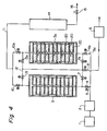
- the method of this invention can be advantageously carried out by a separating device (PSA device) comprising
- This separating device is operated in five steps, i.e., adsorption, pressure equalization (pressure reduction), evacuation, pressure equalization (pressure elevation), and pressure elevation.
- the pressure equalization step is carried out by concurrent pressure equalization whereby a gas is caused to flow in the same direction as the flowing direction of the starting air (gaseous mixture) or countercurrent pressure equalization whereby a gas is caused to flow in a direction opposite to the flowing direction of the starting air. Investigations of the present inventors have shown that the concurrent pressure equalization more easily permits production of a high-purity gas.
- the PSA device It is possible to operate the PSA device in three steps of adsorption, evacuation and pressure elevation, or four steps of adsorption, pressure reduction, purging and pressure elevation by omitting the pressure equalization step.
- To increase the unit power cost in a small-sized PSA device it is frequently advantageous to use two adsorption towers.
- the method of this invention can also be carried out by using a so-called rapid PSA device in which an adsorption-desorption cycle is quickened by using a single tower.
- the pore volume and the pore size distribution of of the porous body of the invention are measured by a mercury penetration method using a porosimeter (Poresizer 9310 made by Shimazu Seisakusho) for a pore diameter range of from 60 ⁇ 10 ⁇ 10m to 500 micrometers.
- a porosimeter Pierizer 9310 made by Shimazu Seisakusho
- pore diameter For a pore diameter of less than 60 ⁇ 10 ⁇ 10m, they are determined by the Kelvin equation from the adsorption isotherm of nitrogen gas.
- Carbon content Measured by an elemental analysis device (CHN CORDER, MF-3 type) made by Yanagimoto Seisakusho Co., Ltd.
- Example 1 As in Example 1, 4 kg of polyvinyl alcohol having a degree of polymerization of 1700 and a degree of saponification of 88% was dissolved in hot water, and 8 kg of wheat starch was added to perform gelatinization. To the resulting solution was added a solution of a water-soluble resol resin (BRL-2894, a product of Showa Polymer Co., Ltd.) in a solids concentration of 60% by weight, and the mixture was fully stirred. Furthermore, the mixture was uniformly mixed with 7 kg of 37% formalin and 3 kg of 30% by weight oxalic acid. The amount of the resulting mixture was adjusted by using a suitable amount of water to adjust its total amount to 100 liters. The mixture was cast in a square mold having a size of 620 x 620 mm and reacted as in Example 1 to form a porous body of PVA/-phenolic synthetic resin.
- a water-soluble resol resin (BRL-2894, a product of Showa Polymer Co., Ltd.
- the porous body was cut into a prism shape having a size of 100 x 100 x 500, and the melamine resin was applied to it as in Example 1 to give a porous body of a synthetic resin composed of 20% by weight of the polyvinyl alcohol-type resin, 20% by weight of the melamine resin and 60% by weight of the phenolic resin.
- the porous body was placed in an electrical furnace, heated in an atmosphere of nitrogen to a predetermined activating temperature at a temperature elevation rate of 50°C/hr, and activated in an atmosphere of steam for a predetermined period of time.
- the physical properties of the resulting activated porous bodies are shown in Table 2.
- the two adsorption towers were used alternately with an adsorption time of 1 minute and a desorption time of 1 minute. At the time of desorption, the gas was forcibly evacuated by a vacuum pump.
- the concentration of the outlet gas from the adsorption tower was analyzed. With sample No. 4, it contained nitrogen in a concentration of 99.2%, but with sample No. 5, its nitrogen concentration was 79.1% showing the same composition as the inlet air.
- the polyvinyl formal porous body was then cut into a solid cylinder having a diameter of 170 mm and a length of 400 mm, immersed in a solution of a water-soluble resol resin (BRL-2854, a product of Showa Polymer Co., Ltd.) in an adjusted concentration, and then dried at 80°C for 24 hours to form a porous body of a syntehtic resin containing 70% of the resol resin.
- a water-soluble resol resin (BRL-2854, a product of Showa Polymer Co., Ltd.) in an adjusted concentration
- the resulting porous body was placed in an electrical furnace, heated at a rate of 100°C/hr to 200°C and then at a rate of 30°C/hr, and carbonized at 660°C to produce a cylindrical adsorbent having an average macropore diameter of 200 micrometers, an apparent density of 0.52 g/cm3, a porosity of 68%, a diameter of 100 mm and a length of 250 mm.
- a scanning electron micrograph (magnification 100X) of a cross section of this adsorbent is shown in Figure 2.
- the cavities are macropores.
- the inlets of these adsorption towers communicate with the outlet of the air dryer 2 via inflow passage pipes 5 and 5a having first on-off valves 4 and 4a.
- 6 represents a vacuum pump and is connected to the inlets of the adsorption towers 3 and 3a by a suction passage pipe 8 equipped with valves 7 and 7a.
- 9 and 9a represent withdrawal passage pipes extending from the outlets of the adsorption towers 3 and 3a respectively and are equipped with second on-off valves 10 and 10a.
- These pipes 9 and 9a are connected to a main pipe 11.
- 12 represents a pressure equalization pipe having valves 13 and 13a and is in communication with the outlets of the adsorption towers 3 and 3a.
- the main pipe 11 is connected to a reservoir tank 14 from which the product is taken out through a product withdrawal pipe 16 having a needle valve 15.
- separation of oxygen and nitrogen in the starting air is carried out as follows:-The starting air is compressed by the air compressor 1, dried by the air dryer 2, and in this state, fed into one adsorption tower 3 from its inlet via the inflow passage pipe 5. At this time, the valve 4a of the inflow passage pipe 5a of the other adsorption tower 3a is off. The compressed air entering the adsorption tower 3 rises through the open cells of the adsorbents formed in a three-dimensional network structure as flow passages.
- the outlet side of the other adsorption tower 3a is closed with the valves 10a, 13 and 13a.
- the vacuum pump 6 By operating the vacuum pump 6 while closing the valve 7 of the suction passage pipe 8 and opening the valve 7a, the inside of the adsorption tower 3a is evacuated by a countercurrent, and the adsorbents are regenerated.
- the adsorption tower 3 after the adsorption step and the adsorption tower 3a after the regeneration step are brought into communication with each other by the pipe 17, the valve 13 and the valve 7a for pressure equalization.
- only the valve 13 on the outlet side of the adsorption tower 3 and the valve 7a on the inlet side of the adsorption tower 3a are open, and all other valves are closed.
- the gas within the adsorption tower 3 which is under a higher pressure goes out from the outlet and enters the inlet of the adsorption tower 3a, whereby pressure equalization is achieved. Thereafter, the valves 13 and 7a are closed and the valve 4a is opened. The adsorption tower 3a thus sets in the pressure elevation and adsorption steps. Meanwhile, the valves 4 and 10 are closed in the adsorption tower 3, and the valve 7 is opened. Thus, the regeneration step is started in the adsorption tower 3.
- All of the above valves are electromagnetic valves, and the series of the valve operations as above are controlled by an on-off control device (not shown)
- the adsorption pressure at this time is adjusted to 4 kg/cm2.G, and the evacuation for regeneration of the adsorbent is carried out to a pressure of less than 13333 Pa (100 torr) by a vacuum pump.
- the above adsorbents had a specific surface area of 640 m2/g.
- the filling density of MSC at this time was 0.61 g/cm3.
- the granular MSC had a specific surface area of 560 m2/g, and the amounts of O2 and N2 adsorbed on it, measured by the same method as in Example 3 above, were 22.1 mg/g and 3.8 mg/g, respectively.
- the reaction product was washhd with water to obtain a porous body of polyvinyl formal (PVF) having a network structure.
- the PVF porous body was cut into a cylindrical shape having a size of 400 ⁇ x 28 ⁇ x 350 mm L and then immersed in a solution of melamine resin (Sumitex Resin M-3, a product of Sumitomo Chemical Co., Ltd.) in a solids concentration of 40%. After centrifugation, the applied melamine resin was cured at 90°C for 24 hours.
- melamine resin Suditex Resin M-3, a product of Sumitomo Chemical Co., Ltd.
- the product was further immersed in a solution of water-soluble resol resin (BRL-2854, a product of Showa Polymer Co, Ltd.) in a solids concentration of 40%, and then heat-treated at 90°C for 24 hours to cure the resol resin.
- a porous body of synthetic resin composed of 20% of polyvinyl formal, 40% of the melamine resin and 40% of the phenolic resin was obtained.
- the synthetic resin porous body was placed in an electrical furnace, and heated at 60°C in an atmosphere of nitrogen and carbonized at 670°C to obtain an adsorbent.
- the mixture was cast in a mold having a size of 320 ⁇ x 28 ⁇ x 1000 mm L, and reacted as in Example 3 to obtain a porous body of a PVA/phenol synthetic resin.
- the porous body was cut into a cylindrical shape having a size of 300 ⁇ x 28 ⁇ x 750 mm L, and the melamine resin was applied as in Example 3 to obtain a porous body of a synthetic resin composed of 20% of polyvinyl alcohol, 20% of the melamine resin and 60% of the phenolic resin.
- the porous body was placed in an electrical furnace, and heated to a predetermined temperature in an atmosphere of nitrogen at a temperature elevation rate of 50°C/hr and activated in an atmosphere of steam for a predetermined period of time to form a cylindrical adsorbent having an outside diameter of 200 mm ⁇ , an inside diameter of 20 mm ⁇ and a height of 500 mm.
- the adsorbent had an average pore diameter of 300 micrometers, an apparent density of 0.60 g/cm3 and a porosity of 62%.
- Two such adsorbents were longitudinally connected and filled in an adsorption tower having an inside diameter of 220 mm and an effective length of 1000 mm.
- the connecting parts were closely adhered to each other, and as shown in Figure 5, the upper and lower end surfaces of the connected adsorbent unit were sealed with thermoplastic resin plates 21. In this state, the adsorbents were filled into adsorption towers 3 and 3a.
- the reference numeral 22 in Figure 5 represents a purging pipe having a valve 23, and keeps the reservoir tank 14 and the outlets of the adsorbent towers 3 and 3a in communication with each other.
- the reference numeral 24 represents a release pipe.
- the other parts are substantially the same as in Figure 3. This device is designed for production of oxygen-enriched air. Oxygen is adsorbed in the adsorption tower 3, and air rich in nitrogen is released from the outlet of the adsorption tower 3 by the release pipe 24 as shown by an arrow.
- the oxygen-enriched air stored in the reservoir tank 14 is fed into the adsorption tower 3a from the purging pipe 22 to purge the adsorption tower 3a.
- oxygen is taken out from the inlet of the adsorption tower 3a by sucking with the vacuum pump 6, and stored in the reservoir tank.
- the adsorbent had a specific surface area of 625 m2/g, and the amounts of O2 and N2 adsorbed on it measured by the method described in Example 3 were 23.8 ml/g and 3.2 mg/g.
- An adsorbent having an average macropore diameter of 300 micrometers, an apparent density of 0.58 g/cm3 and a porosity of 64% was produced in the same way as in Example 3, and set in the same device as used in Example 3.
- the pressure at the time of adsorption was adjusted to 7 kg/cm2.G.
- the adsorbent was regenerated at amospheric pressure without using a vacuum pump.
- the amount of nitrogen gas withdrawn was 10 liters/min., and it contained 0.09% of O2.
- the amount of the nitrogen gas withdrawn was 20 liters/min., it contained 0.9% of oxygen.
- the porous body was placed in an electrical furnace, heated in an atmosphere of nitrogen at a rate of 60°C/hr, and maintained at 680°C for 2 hours to carbonize it.
- a cylindrical adsorbent was obtained which had an average macropore diameter of 250 micrometers, an apparent density of 0.54 g/cm3, a porosity of 67%, a diameter of 100 mm and a length of 250 mm.
- Four such cylindrical adsorbents connected to each other longitudinally were filled in each of two adsorbent towers as in Example 3 (the filling volume of the adsorbents in each tower was 100 mm ⁇ x 1000 mm L).
- Example 3 the device was operated under the operating conditions shown in Table 9, and the relation between the amount of hydrogen gas withdrawn and its purity was examined.
- the adsorption pressure was adjusted to 9 kg/cm2.G, and the regeneration of the adsorbent was carried out under a reduced pressure of less than 100 torr.
- the relation between the amount of the hydrogen gas withdrawn and its purity is shown in Table 10.
- the cylindrical adsorbent filled in the adsorption tower had a specific surface area of 64 m2/g.
- Comparative Example 2 in Table 10 The results of Comparative Example 2 in Table 10 were obtained when granular MSC having a size of 3 mm ⁇ x 6 mm L was filled into two adsorption towers as in Example 3 to a filling volume of 100 mm ⁇ x 1000 mm L, and the same hydrogen separating operation as in Example 7 was carried out using these adsoprtion tower.
- the filling density of the granular MSC was 0.57 g/cm3, and its specific surface area was 610 m2/g.
- Example 7 As in Example 7, a starting gaseous mixture composed of 75% of hydrogen gas and 25% of carbon dioxide was introduced and separation of hydrogen gas was carried out.
- the operating conditions of the PSA device were the same as in Example 7.
- Comparative Example 3 was carried out as in Comparative Example 2.
- Table 11 shows the relation between the amount of the product gas withdrawn and its purity.
- Table 11 Amount of hydrogen gas withdrawn (liters/min.) H2 concentration (%)
- Example 8 Comparative Example 3 15 99.999 99.990 30 99.99 99.90 50 99.2 97.6 70 96.7 95.1 90 92.9 88.6
- Example 7 a starting gaseous mixture composed of 50% of carbon momoxide and 50% of methane was introduced, and the separation of carbon monoxide was tested.
- the operating conditions of the PSA device are shown in Table 12.
- the adsorption pressure was 9 kg/cm2.G. cm2.G, and the regeneration was carried out at less than 13333 Pa (100 torr).
Landscapes
- Chemical & Material Sciences (AREA)
- Analytical Chemistry (AREA)
- Chemical Kinetics & Catalysis (AREA)
- Engineering & Computer Science (AREA)
- General Chemical & Material Sciences (AREA)
- Oil, Petroleum & Natural Gas (AREA)
- Inorganic Chemistry (AREA)
- Organic Chemistry (AREA)
- Separation Of Gases By Adsorption (AREA)
- Oxygen, Ozone, And Oxides In General (AREA)
- Solid-Sorbent Or Filter-Aiding Compositions (AREA)
Claims (11)
- Procédé de séparation d'au moins un gaz d'un mélange gazeux, comprenant la mise en contact d'un mélange gazeux contenant un premier et un second gaz ayant différentes compositions chimiques, en une quantité d'au moins 50 % en volume calculé sur l'ensemble du mélange, avec un corps poreux carboné servant de tamis moléculaire, ledit corps poreux ayant (1) une teneur en carbone d'au moins 85 % en poids, (2) une densité apparente de 0,1 à 0,8 g/cm³, (3) une porosité de 50 à 95 %, (4) une valeur minimale de la distribution des diamètres des pores pour un diamètre de pore ne dépassant pas 10.10⁻¹⁰ m (10A) et
un volume de pore ne dépassant pas 0,1 cm³/g pour un diamètre de pore allant de 15 à 200.10⁻¹° m et contenant (5) des cellules ouvertes ayant un diamètre moyen de 1 à 500 micromètres. - Procédé selon la revendication 1, dans lequel le premier gaz est l'azote, le second gaz est l'oxygène et le mélange gazeux est l'air.
- Procédé selon la revendication 1, dans lequel le premier gaz est l'hydrogène et le second gaz est le méthane.
- Procédé selon la revendication 1, dans lequel le premier gaz est l'hydrogène, le second gaz est le dioxyde de carbone.
- Procédé selon la revendication 1, dans lequel le premier gaz est le monoxyde de carbone, et le second gaz est le méthane.
- Procédé selon la revendication 1, dans lequel la quantité du premier et du second gaz est d'au moins 75 % en volume du volume total du mélange gazeux.
- Procédé selon la revendication 1, dans lequel le corps poreux a une teneur en carbone d'au moins 90 % en poids.
- Procédé selon la revendication 1 où au moins une partie de la surface extérieure du corps poreux, dans une direction parallèle à la direction du passage du mélange gazeux à travers les cellules ouvertes du corps poreux, est fermée hermétiquement au mélange gazeux.
- Procédé selon la revendication 1, dans lequel le corps poreux est de forme cylindrique, circulaire ou a la forme d'un disque.
- Procédé selon la revendication 1, dans lequel le mélange gazeux est mis en contact du corps poreux à une pression comprise entre la pression atmosphérique et des pressions plus élevées.
- Procédé de séparation au moins d'un premier gaz d'un mélange gazeux, comprenant :(1) la mise en contact du mélange gazeux contenant un premier et un second gaz, ayant différentes compositions chimiques, sous une pression élevée, avec un corps poreux carboné tel que défini dans la revendication 1,(2) suivi de la désorption du second gaz physiquement adsorbé sur le corps poreux, sous pression atmosphérique ou sous pression réduite, et(3) répétition des étapes (1) et (2).
Applications Claiming Priority (2)
| Application Number | Priority Date | Filing Date | Title |
|---|---|---|---|
| JP248146/86 | 1986-10-18 | ||
| JP61248146A JPH07108365B2 (ja) | 1986-10-18 | 1986-10-18 | 空気分離法およびその装置 |
Publications (3)
| Publication Number | Publication Date |
|---|---|
| EP0264523A2 EP0264523A2 (fr) | 1988-04-27 |
| EP0264523A3 EP0264523A3 (en) | 1990-05-16 |
| EP0264523B1 true EP0264523B1 (fr) | 1993-06-09 |
Family
ID=17173906
Family Applications (1)
| Application Number | Title | Priority Date | Filing Date |
|---|---|---|---|
| EP87103169A Expired - Lifetime EP0264523B1 (fr) | 1986-10-18 | 1987-03-06 | Méthode de séparation d'un mélange gazeux |
Country Status (4)
| Country | Link |
|---|---|
| US (1) | US4790859A (fr) |
| EP (1) | EP0264523B1 (fr) |
| JP (1) | JPH07108365B2 (fr) |
| DE (1) | DE3786140T2 (fr) |
Families Citing this family (29)
| Publication number | Priority date | Publication date | Assignee | Title |
|---|---|---|---|---|
| US4933314A (en) * | 1987-03-10 | 1990-06-12 | Kanebo Ltd. | Molecular sieving carbon |
| DE3941487C1 (fr) * | 1989-12-15 | 1991-04-25 | Bergwerksverband Gmbh, 4300 Essen, De | |
| JP2619839B2 (ja) * | 1990-01-31 | 1997-06-11 | 鐘紡株式会社 | 窒素ガスの分離方法 |
| JP2623487B2 (ja) * | 1990-02-10 | 1997-06-25 | 鐘紡株式会社 | 窒素ガスの分離方法 |
| US5071450A (en) * | 1990-09-14 | 1991-12-10 | Air Products And Chemicals, Inc. | Modified carbon molecular sieve adsorbents |
| US5626650A (en) * | 1990-10-23 | 1997-05-06 | Catalytic Materials Limited | Process for separating components from gaseous streams |
| US5240474A (en) * | 1991-01-23 | 1993-08-31 | Air Products And Chemicals, Inc. | Air separation by pressure swing adsorption with a high capacity carbon molecular sieve |
| US5261948A (en) * | 1992-09-10 | 1993-11-16 | University Of Delaware | Carbon molecular sieve for the kinetic separation of acid gases and fluorocarbons |
| JPH0760048A (ja) * | 1993-08-26 | 1995-03-07 | Mitsubishi Petrochem Eng Co Ltd | 酸化エチレン製造プラント排ガスからのエチレンの回収法 |
| JPH0790409A (ja) * | 1993-09-13 | 1995-04-04 | Kanebo Ltd | アルミニウム溶湯の脱水素方法 |
| US5658372A (en) * | 1995-07-10 | 1997-08-19 | Corning Incorporated | System and method for adsorbing contaminants and regenerating the adsorber |
| CA2187490A1 (fr) * | 1995-11-17 | 1997-05-18 | Kishor Purushottam Gadkaree | Methode pour l'obtention de corps de charbon active possedant des proprietes d'adsorption ameliorees |
| US5972077A (en) * | 1996-02-15 | 1999-10-26 | Lockheed Martin Energy Research Corporation | Gas separation device based on electrical swing adsorption |
| US6187713B1 (en) | 1996-10-31 | 2001-02-13 | Corning Incorporated | Method of making activated carbon bodies having improved adsorption properties |
| US5827355A (en) * | 1997-01-31 | 1998-10-27 | Lockheed Martin Energy Research Corporation | Carbon fiber composite molecular sieve electrically regenerable air filter media |
| US5912424A (en) * | 1997-03-31 | 1999-06-15 | Lockheed Martin Energy Research Corporation | Electrical swing adsorption gas storage and delivery system |
| FR2764522B1 (fr) * | 1997-06-12 | 1999-07-16 | Air Liquide | Procede et installation de separation d'air par adsorption |
| DE19745549C2 (de) * | 1997-10-10 | 1999-11-04 | Mannesmann Ag | Gasspeicher |
| US6024781A (en) * | 1998-04-17 | 2000-02-15 | The Boc Group, Inc. | Separation of carbon dioxide and hydrocarbons |
| US6027549A (en) * | 1998-04-28 | 2000-02-22 | Air Products And Chemicals, Inc. | Adjusted density carbon for hydrogen PSA |
| FR2799991B1 (fr) * | 1999-10-26 | 2002-10-11 | Air Liquide | Procede de production d'hydrogene utilisant un adsorbant carbone a parametres de dubinin selectionnes |
| JP4761635B2 (ja) * | 2000-03-27 | 2011-08-31 | 大陽日酸株式会社 | 窒素ガス発生方法 |
| US6626981B2 (en) * | 2000-07-07 | 2003-09-30 | Advanced Fuel Research, Inc. | Microporous carbons for gas storage |
| JP3524527B2 (ja) * | 2001-09-05 | 2004-05-10 | 日本酸素株式会社 | 吸着剤およびこれを用いた窒素製造方法ならびに製造装置 |
| JP3617835B2 (ja) * | 2002-09-20 | 2005-02-09 | 東洋炭素株式会社 | フッ素ガス発生装置 |
| US7172645B1 (en) * | 2003-06-30 | 2007-02-06 | Sun Microsystems, Inc. | Gas filtration and storage using activated carbon/graphite foam monoliths |
| US7655703B2 (en) * | 2007-01-26 | 2010-02-02 | Inentec Llc | Method and apparatus for methanol and other fuel production |
| WO2011139894A1 (fr) * | 2010-05-05 | 2011-11-10 | Linde Aktiengesellschaft | Méthode et dispositif de fabrication d'un gaz de pureté élevée |
| EP4288185A4 (fr) * | 2021-02-04 | 2025-12-03 | Indian Inst Scient | Système de séparation d'hydrogène d'un gaz d'alimentation |
Family Cites Families (23)
| Publication number | Priority date | Publication date | Assignee | Title |
|---|---|---|---|---|
| US3454502A (en) * | 1966-04-27 | 1969-07-08 | Calgon Corp | Activated carbon tablet |
| US3545622A (en) * | 1967-07-27 | 1970-12-08 | Alco Controls Corp | Permeable filter and drier block |
| US3639266A (en) * | 1968-04-08 | 1972-02-01 | Fmc Corp | Carbonization of compressed cellulose crystallite aggregates |
| US3573122A (en) * | 1968-08-23 | 1971-03-30 | Dow Chemical Co | Preparation of conductive materials |
| GB1364674A (en) * | 1971-04-23 | 1974-08-29 | Bergwerksverband Gmbh | Carbon-containing molecular sieves |
| GB1429476A (en) * | 1972-07-05 | 1976-03-24 | Secr Defence | Filter assemblies |
| DE2453204A1 (de) * | 1974-11-09 | 1976-05-13 | Philips Patentverwaltung | Verfahren zum herstellen eines ganz oder teilweise poroesen koerpers aus glasartigem kohlenstoff |
| US4082694A (en) * | 1975-12-24 | 1978-04-04 | Standard Oil Company (Indiana) | Active carbon process and composition |
| US4350672A (en) * | 1976-02-25 | 1982-09-21 | United Technologies Corporation | Binderless carbon or graphite articles |
| FR2390381A1 (fr) * | 1977-05-12 | 1978-12-08 | Lorraine Carbone | Carbone ou graphite artificiel a double porosite et methode de fabrication |
| US4154704A (en) * | 1978-01-23 | 1979-05-15 | Chemotronics International, Inc. | Activated reticulated or unreticulated carbon structures |
| NL7804596A (en) * | 1978-04-28 | 1979-10-30 | Essex Bv Ing Buero | Selective sepn. of gaseous component by pressure swing adsorption - using radial gas flow to optimise utilisation of adsorbent bed in cylindrical vessel |
| CA1110223A (fr) * | 1979-02-15 | 1981-10-06 | James W. Neely | Produit de coagulation de polymere partiellement pyrolyse |
| DE3105887C2 (de) * | 1980-02-19 | 1983-07-14 | Schumacher'sche Fabrik Gmbh & Co Kg, 7120 Bietigheim-Bissingen | Verfahren zur Herstellung von Filterkörpern zur Feinfiltration von Fluiden |
| US4381929A (en) * | 1980-04-25 | 1983-05-03 | Nippon Soken, Inc. | Apparatus for adsorbing fuel vapor |
| JPS5751109A (en) * | 1980-09-08 | 1982-03-25 | Kanebo Ltd | Preparation of porous carbon |
| US4518704A (en) * | 1980-12-08 | 1985-05-21 | Kyoto Ceramic Kabushiki Kaisha | Activated carbon formed body and method of producing the same |
| JPS57105239A (en) * | 1980-12-22 | 1982-06-30 | Kobe Steel Ltd | Honeycomb type catalyst carrier comprising vitreous carbonacious substance |
| FR2510539A1 (fr) * | 1981-07-28 | 1983-02-04 | Expertises Sa Cie Maritime | Procede et installation d'epuration de l'helium contenu dans un melange de gaz |
| JPS5854082A (ja) * | 1981-09-22 | 1983-03-30 | 倉敷紡績株式会社 | セルロ−ス系繊維の改質方法 |
| DE3214771A1 (de) * | 1982-04-21 | 1983-10-27 | Bergwerksverband Gmbh, 4300 Essen | Verfahren zur gewinnung von edelgasen mit kleinen atomdurchmessern, insbesondere helium, aus sauerstoff und/oder stickstoff enthaltenden gasgemischen |
| JPS616108A (ja) * | 1984-06-15 | 1986-01-11 | Kanebo Ltd | 分子ふるい炭素 |
| JPS6131052A (ja) * | 1984-07-25 | 1986-02-13 | Fuji Seiki Kk | 飯定量盛付機 |
-
1986
- 1986-10-18 JP JP61248146A patent/JPH07108365B2/ja not_active Expired - Fee Related
-
1987
- 1987-03-03 US US07/021,119 patent/US4790859A/en not_active Expired - Fee Related
- 1987-03-06 EP EP87103169A patent/EP0264523B1/fr not_active Expired - Lifetime
- 1987-03-06 DE DE87103169T patent/DE3786140T2/de not_active Expired - Fee Related
Also Published As
| Publication number | Publication date |
|---|---|
| EP0264523A3 (en) | 1990-05-16 |
| DE3786140D1 (de) | 1993-07-15 |
| JPS63104629A (ja) | 1988-05-10 |
| JPH07108365B2 (ja) | 1995-11-22 |
| US4790859A (en) | 1988-12-13 |
| DE3786140T2 (de) | 1993-11-25 |
| EP0264523A2 (fr) | 1988-04-27 |
Similar Documents
| Publication | Publication Date | Title |
|---|---|---|
| EP0264523B1 (fr) | Méthode de séparation d'un mélange gazeux | |
| KR100851241B1 (ko) | 산소ㆍ질소 혼합 가스로부터 질소를 분리하기 위한흡착제와 이를 이용한 질소 제조 방법 | |
| KR100291115B1 (ko) | 제올라이트및알루미나를사용한흡착방법 | |
| Sircar et al. | Activated carbon for gas separation and storage | |
| US4810266A (en) | Carbon dioxide removal using aminated carbon molecular sieves | |
| EP0282053B1 (fr) | Procédé de fabrication et utilisation de tamis moléculaire en carbone | |
| JP2988625B2 (ja) | 温度スイング吸着方法 | |
| US3808773A (en) | Process and apparatus for the adsorptive purification of gases | |
| JP2785870B2 (ja) | 圧力スイング吸着法 | |
| Serna-Guerrero et al. | Triamine-grafted pore-expanded mesoporous silica for CO2 capture: effect of moisture and adsorbent regeneration strategies | |
| KR950014208B1 (ko) | 고용량 탄소 분자체를 사용하는 압력 변동 흡착에 의한 공기 분리 방법 | |
| EP0474106B1 (fr) | Procédé de préparer tamis moléculaires de carbone modifiés pour la séparation de gaz | |
| WO2022265651A1 (fr) | Craquage d'ammoniac pour de l'hydrogène vert | |
| US4011065A (en) | Process for the enrichment of gases | |
| WO1996033801A1 (fr) | Adsorbant charbonneux, son procede de production, et technique et appareil pour la separation de gaz | |
| WO1989004810A1 (fr) | Charbon actif et procede de production | |
| EP0497154A1 (fr) | Charbon de noix de coco de capacité élevée pour des tamis moléculaires de charbon | |
| US4015956A (en) | Process and arrangement for the enrichment of gases | |
| JP2002177773A (ja) | モノリス吸着剤の活性化方法 | |
| EP0723802A2 (fr) | Procédé pour la séparation sélective de dioxide de carbone d'un gaz de combustion | |
| Nandi et al. | Carbon molecular sieves for the concentration of oxygen from air | |
| JP2546797B2 (ja) | 気体混合物の分離法 | |
| US10661219B2 (en) | Separation of nitrogen from hydrocarbon gas using pyrolyzed sulfonated macroporous ion exchange resin | |
| RU2765720C1 (ru) | Способ декарбонизации газовых потоков | |
| JPH10180091A (ja) | 一酸化炭素吸着剤及びその製造方法 |
Legal Events
| Date | Code | Title | Description |
|---|---|---|---|
| PUAI | Public reference made under article 153(3) epc to a published international application that has entered the european phase |
Free format text: ORIGINAL CODE: 0009012 |
|
| AK | Designated contracting states |
Kind code of ref document: A2 Designated state(s): CH DE FR GB IT LI NL |
|
| PUAL | Search report despatched |
Free format text: ORIGINAL CODE: 0009013 |
|
| AK | Designated contracting states |
Kind code of ref document: A3 Designated state(s): CH DE FR GB IT LI NL |
|
| 17P | Request for examination filed |
Effective date: 19900801 |
|
| 17Q | First examination report despatched |
Effective date: 19910319 |
|
| GRAA | (expected) grant |
Free format text: ORIGINAL CODE: 0009210 |
|
| ITF | It: translation for a ep patent filed | ||
| AK | Designated contracting states |
Kind code of ref document: B1 Designated state(s): CH DE FR GB IT LI NL |
|
| REF | Corresponds to: |
Ref document number: 3786140 Country of ref document: DE Date of ref document: 19930715 |
|
| ET | Fr: translation filed | ||
| PLBE | No opposition filed within time limit |
Free format text: ORIGINAL CODE: 0009261 |
|
| STAA | Information on the status of an ep patent application or granted ep patent |
Free format text: STATUS: NO OPPOSITION FILED WITHIN TIME LIMIT |
|
| 26N | No opposition filed | ||
| PGFP | Annual fee paid to national office [announced via postgrant information from national office to epo] |
Ref country code: CH Payment date: 19950224 Year of fee payment: 9 |
|
| PGFP | Annual fee paid to national office [announced via postgrant information from national office to epo] |
Ref country code: FR Payment date: 19950227 Year of fee payment: 9 |
|
| PGFP | Annual fee paid to national office [announced via postgrant information from national office to epo] |
Ref country code: GB Payment date: 19950302 Year of fee payment: 9 Ref country code: DE Payment date: 19950302 Year of fee payment: 9 |
|
| PGFP | Annual fee paid to national office [announced via postgrant information from national office to epo] |
Ref country code: NL Payment date: 19950331 Year of fee payment: 9 |
|
| PG25 | Lapsed in a contracting state [announced via postgrant information from national office to epo] |
Ref country code: GB Effective date: 19960306 |
|
| PG25 | Lapsed in a contracting state [announced via postgrant information from national office to epo] |
Ref country code: LI Effective date: 19960331 Ref country code: CH Effective date: 19960331 |
|
| PG25 | Lapsed in a contracting state [announced via postgrant information from national office to epo] |
Ref country code: NL Effective date: 19961001 |
|
| GBPC | Gb: european patent ceased through non-payment of renewal fee |
Effective date: 19960306 |
|
| REG | Reference to a national code |
Ref country code: CH Ref legal event code: PL |
|
| PG25 | Lapsed in a contracting state [announced via postgrant information from national office to epo] |
Ref country code: FR Effective date: 19961129 |
|
| NLV4 | Nl: lapsed or anulled due to non-payment of the annual fee |
Effective date: 19961001 |
|
| PG25 | Lapsed in a contracting state [announced via postgrant information from national office to epo] |
Ref country code: DE Effective date: 19961203 |
|
| REG | Reference to a national code |
Ref country code: FR Ref legal event code: ST |
|
| PG25 | Lapsed in a contracting state [announced via postgrant information from national office to epo] |
Ref country code: IT Free format text: LAPSE BECAUSE OF NON-PAYMENT OF DUE FEES;WARNING: LAPSES OF ITALIAN PATENTS WITH EFFECTIVE DATE BEFORE 2007 MAY HAVE OCCURRED AT ANY TIME BEFORE 2007. THE CORRECT EFFECTIVE DATE MAY BE DIFFERENT FROM THE ONE RECORDED. Effective date: 20050306 |