EP0264970B1 - Système de transmission - Google Patents
Système de transmission Download PDFInfo
- Publication number
- EP0264970B1 EP0264970B1 EP87117240A EP87117240A EP0264970B1 EP 0264970 B1 EP0264970 B1 EP 0264970B1 EP 87117240 A EP87117240 A EP 87117240A EP 87117240 A EP87117240 A EP 87117240A EP 0264970 B1 EP0264970 B1 EP 0264970B1
- Authority
- EP
- European Patent Office
- Prior art keywords
- gear
- cylinder member
- thrust force
- ring gear
- planetary gear
- Prior art date
- Legal status (The legal status is an assumption and is not a legal conclusion. Google has not performed a legal analysis and makes no representation as to the accuracy of the status listed.)
- Expired - Lifetime
Links
- 230000005540 biological transmission Effects 0.000 title claims description 29
- 238000005192 partition Methods 0.000 description 12
- 230000008878 coupling Effects 0.000 description 8
- 238000010168 coupling process Methods 0.000 description 8
- 238000005859 coupling reaction Methods 0.000 description 8
- 239000012530 fluid Substances 0.000 description 7
- 239000003921 oil Substances 0.000 description 6
- 239000002131 composite material Substances 0.000 description 4
- 230000003247 decreasing effect Effects 0.000 description 4
- 239000011796 hollow space material Substances 0.000 description 4
- 238000010276 construction Methods 0.000 description 3
- 239000000463 material Substances 0.000 description 2
- 230000002093 peripheral effect Effects 0.000 description 2
- 230000002028 premature Effects 0.000 description 2
- RYGMFSIKBFXOCR-UHFFFAOYSA-N Copper Chemical compound [Cu] RYGMFSIKBFXOCR-UHFFFAOYSA-N 0.000 description 1
- 230000004323 axial length Effects 0.000 description 1
- 238000006243 chemical reaction Methods 0.000 description 1
- 229910052802 copper Inorganic materials 0.000 description 1
- 239000010949 copper Substances 0.000 description 1
- 239000010720 hydraulic oil Substances 0.000 description 1
- 239000011347 resin Substances 0.000 description 1
- 229920005989 resin Polymers 0.000 description 1
- 238000000638 solvent extraction Methods 0.000 description 1
- 238000003466 welding Methods 0.000 description 1
Images

Classifications
-
- F—MECHANICAL ENGINEERING; LIGHTING; HEATING; WEAPONS; BLASTING
- F16—ENGINEERING ELEMENTS AND UNITS; GENERAL MEASURES FOR PRODUCING AND MAINTAINING EFFECTIVE FUNCTIONING OF MACHINES OR INSTALLATIONS; THERMAL INSULATION IN GENERAL
- F16H—GEARING
- F16H47/00—Combinations of mechanical gearing with fluid clutches or fluid gearing
- F16H47/06—Combinations of mechanical gearing with fluid clutches or fluid gearing the fluid gearing being of the hydrokinetic type
- F16H47/065—Combinations of mechanical gearing with fluid clutches or fluid gearing the fluid gearing being of the hydrokinetic type the mechanical gearing comprising gearing of the friction or endless flexible member type
-
- F—MECHANICAL ENGINEERING; LIGHTING; HEATING; WEAPONS; BLASTING
- F16—ENGINEERING ELEMENTS AND UNITS; GENERAL MEASURES FOR PRODUCING AND MAINTAINING EFFECTIVE FUNCTIONING OF MACHINES OR INSTALLATIONS; THERMAL INSULATION IN GENERAL
- F16H—GEARING
- F16H37/00—Combinations of mechanical gearings, not provided for in groups F16H1/00 - F16H35/00
- F16H37/02—Combinations of mechanical gearings, not provided for in groups F16H1/00 - F16H35/00 comprising essentially only toothed or friction gearings
- F16H37/021—Combinations of mechanical gearings, not provided for in groups F16H1/00 - F16H35/00 comprising essentially only toothed or friction gearings toothed gearing combined with continuously variable friction gearing
- F16H37/022—Combinations of mechanical gearings, not provided for in groups F16H1/00 - F16H35/00 comprising essentially only toothed or friction gearings toothed gearing combined with continuously variable friction gearing the toothed gearing having orbital motion
-
- F—MECHANICAL ENGINEERING; LIGHTING; HEATING; WEAPONS; BLASTING
- F16—ENGINEERING ELEMENTS AND UNITS; GENERAL MEASURES FOR PRODUCING AND MAINTAINING EFFECTIVE FUNCTIONING OF MACHINES OR INSTALLATIONS; THERMAL INSULATION IN GENERAL
- F16H—GEARING
- F16H37/00—Combinations of mechanical gearings, not provided for in groups F16H1/00 - F16H35/00
- F16H37/02—Combinations of mechanical gearings, not provided for in groups F16H1/00 - F16H35/00 comprising essentially only toothed or friction gearings
- F16H37/021—Combinations of mechanical gearings, not provided for in groups F16H1/00 - F16H35/00 comprising essentially only toothed or friction gearings toothed gearing combined with continuously variable friction gearing
- F16H2037/023—Combinations of mechanical gearings, not provided for in groups F16H1/00 - F16H35/00 comprising essentially only toothed or friction gearings toothed gearing combined with continuously variable friction gearing the combined gearing being provided with at least two forward and one reverse ratio in a serially arranged sub-transmission
-
- F—MECHANICAL ENGINEERING; LIGHTING; HEATING; WEAPONS; BLASTING
- F16—ENGINEERING ELEMENTS AND UNITS; GENERAL MEASURES FOR PRODUCING AND MAINTAINING EFFECTIVE FUNCTIONING OF MACHINES OR INSTALLATIONS; THERMAL INSULATION IN GENERAL
- F16H—GEARING
- F16H57/00—General details of gearing
- F16H57/02—Gearboxes; Mounting gearing therein
- F16H2057/02039—Gearboxes for particular applications
- F16H2057/02043—Gearboxes for particular applications for vehicle transmissions
-
- F—MECHANICAL ENGINEERING; LIGHTING; HEATING; WEAPONS; BLASTING
- F16—ENGINEERING ELEMENTS AND UNITS; GENERAL MEASURES FOR PRODUCING AND MAINTAINING EFFECTIVE FUNCTIONING OF MACHINES OR INSTALLATIONS; THERMAL INSULATION IN GENERAL
- F16H—GEARING
- F16H57/00—General details of gearing
- F16H57/02—Gearboxes; Mounting gearing therein
- F16H57/037—Gearboxes for accommodating differential gearings
Definitions
- This invention relates to a transmission system as specified in the preamble of the claim 1.
- FR-A-2 191 669 discloses a transmission system comprising a braking device of a friction multi-plate engaging type and a planetary gear device in a case member, said braking device being interposed between a ring gear of said planetary gear device and said case member, and said braking device being provided with a cylinder member coupled thereto by means of a piston.
- the gear teeth are straight. Therefore, no axial force occurs at the ring gear.
- the ring gear has a helical gear mesh, thereby generating a thrust force.
- This thrust force has to be received by a cover ring of the braking device, whereby the durability of the cover ring is reduced.
- the present invention contemplates that the direction of a thrust force generated in the cylinder member of the braking device is made opposite to the direction of a thrust force generated in the ring gear of the planetary gear device and the cylinder member is abutted against the ring gear, to thereby offset the thrust forces.
- the braking device is provided thereon with the cylinder member, to which a piston is coupled, formed separately of the case member, the cylinder member is engaged with the case member through the cover ring in the axial direction, whereby the thrust force generated in the cylinder member is received by the case member, and the ring gear of the planetary gear device is disposed to generate the thrust force opposite in direction to the thrust force generated in the cylinder member, whereby the cylinder member and the ring gear are abutted against each other to thereby receive the thrust forces in the directions opposite to each other.
- the thrust force generated in the ring gear of the planetary gear device is received by the cylinder member of the braking device, whereby the thrust force generated in the cylinder member is decreased in value by the thrust force generated in the ring gear. Because of this, the load acting on the cover ring receiving the thrust force of the cylinder member is decreased in value by the thrust force of the ring gear. In consequence, the load acting on the cover ring for engaging the cylinder member with the case member can be reduced, so that the premature fatigue of the cover ring can be avoided and the durability of the braking device can be improved.
- the ring gear of the planetary gear device can receive the thrust force of the cylinder member only by being abutted against the cylinder member, so that the construction thereof for receiving the thrust force can be made into a relatively simple system.
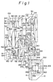
- the case members include a fluid coupling case member 10, a main case member 12 and a cover member 14.
- the fluid coupling case member 10 forms a fluid coupling device chamber 52, in which is housed the fluid coupling device 50.
- the main case member 12 and the cover member 14 form a belt type CVT device chamber 102, in which is housed the belt type CVT device 100.
- the main case member 12 in the lower portion of the main case member 12, the main case member 12 forms an auxiliary transmission device chamber 202, in which is housed the auxiliary transmission device 200.
- the fluid coupling case member 10 forms a differential gear case 302, in which are housed a reduction gear device 300 and a differential gear device 350.
- the auxiliary transmission device 200 The auxiliary transmission device 200.
- the auxiliary transmission device 200 is provided at the output side of the belt type CVT device 100. More specifically, the auxiliary transmission device 200 is disposed on one and the same axial line as the rotary shaft 180 of the output pulley 150.
- the auxiliary transmission device 200 includes a Ravignawx type composite planetary gear device 210, two braking devices 230 and 240, and a clutch device 250.
- the Ravignawx type composite planetary gear device 210 is constituted by elements including: a first sun gear 212 and a second sun gear 214; a first planetary gear 216 being in mesh with the first sun gear 212; a second planetary gear being in mesh with this first planetary gear 216 and the second sun gear 214; a ring gear 220 being in mesh with the first planetary gear 216 and a carrier 222 for rotatably supporting the first planetary gear 216 and the second planetary gear 218.
- the elements of the above-described Ravignawx type composite planetary gear device 210, the two braking devices 230 and 240, and the clutch device 250 are connected to each other between the rotary shaft 180 of the input pulley 150 and an output shaft 310 of the reduction gear device 300 in the following manner.
- the first sun gear 212 is connected to the rotary shaft 180 through the clutch device 250
- the second sun gear 214 is directly connected to the rotary shaft 180 through the spline coupling.
- the first sun gear 212 has the braking device 230 between the partition member 12a and itself.
- the ring gear 220 has the braking device 240 between the partition member 12a and itself.
- the carrier 222 as being an output member is spline-coupled to the output shaft 310 of the reduction gear device 300.
- the carrier 222 and the output shaft 310 are detachably, power-transmissibly coupled to each other.
- the auxiliary transmission device 200 may obtain shift speeds including two forward speeds and one backward speed by selectively feeding an working hydraulic pressure to each hydraulic pressure servo device of the two braking devices 230, 240 and the clutch device 250.
- the forward-first speed The braking device 230 is put into the working condition, the clutch device 250 and the braking device 240 are put into non-working conditions, so that this forward-first speed can be established.
- the rotary force is inputted from the second sun gear 214, the first planetary gear 216 and the second planetary gear 218 are rotated by this second sun gear 214, a planetary revolution on the first sun gear 212 fixed by the braking device 230 is taken off from the carrier 222 into the output shaft 310 in a manner to be reduced in speed.
- the forward-second speed The clutch device 250 is put into the working condition, the braking devices 230 and 240 are put into non-working conditions, so that this forward-second speed can be established.
- the rotary force is simultaneously inputted from the first sun gear 212 and the second sun gear 214, the Ravignawx type composite planetary gear device 210 comes into an integrally rotating condition. Because of this, an input rotation is taken off into the carrier 222 as it is.
- the backward speed The braking device 240 is put into the working condition, the clutch device 250 and the braking device 230 are put into non-working conditions, so that this backward speed can be established.
- the rotary force is inputted from the second sun gear 214, the first planetary gear 216 and the second planetary gear 218 are rotated by this second sun gear, a planetary revolution on the internal teeth of the ring gear 220 fixed by the braking device 240 is taken off from the carrier 222 in a manner to be reduced in speed and in a reverse rotating condition.
- the clutch device 250 disposed in front part of the auxiliary transmission device 200 is of the friction multi-plate engaging type.
- a frictionally engaging member 252 wherein a plurality of disc plates and a plurality of friction plates are assembled together between a hub 256 and a drum 258.
- the hub 256 is spline-coupled at the inner end thereof to the rotary shaft 180 in a manner to be integral in the rotating direction, but slidable in the axial direction.
- the drum 258 is power-transmissibly connected to the first sun gear 212 through a disc-shaped flange member 260.
- the inner end portion 260a of the flange member 260 is integrally connected to the first sun gear 212 by the welding.
- the connection between the inner end portion 260a of this flange member 260 and the first sun gear 212 is made at a position in a hollow space 404 formed by the carrier 222a of the side of the flange member 260 and the first sun 212. More specifically, the inner end of the carrier 222a is not extended inwardly in the radial direction, formed to be somewhat short, and forms the hollow space 404 between the first sun gear and itself.
- the inner portion 260a of the flange member 260 is bent to the direction of this hollow space 404 to be connected to the first sun gear 212 in the hollow space 404.
- the position where the first sun gear 212 is connected to the inner portion 260a of the flange member 260 is located radially inwardly of the carrier 222a and also within the axial width of the carrier 222a.
- the axial length of the transmission system can be decreased by the axial width of the carrier 222a.
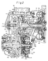
- the first sun gear 212 to which the flange member 260 is integrally connected, is formed of a helical gear, and, referring to Fig. 3, generates a thrust force to the left by the meshing engagement with the planetary gear 216 during the power transmission.
- This thrust force is received by the inner peripheral portion of the hub 256, a base portion 560b of a U-shape in cross section to be described hereunder, and a projected portion 12b of the partition member 12a through thrust bearings 550, 552 and 554 interposed between the hub 256 and the base portion 560b.
- a piston 254 is coupled to a cylinder member 262, and, when the working hydraulic pressure is fed to a working oil chamber 264 defined by the cylinder member 262, the piston 254 is operated to bring a frictionally engaging member 252 into an engagement.
- This engagement rotatably connects the rotary shaft 180 and the first sun gear 212, whereby rotation of the ratary shaft 180 is transmitted to the first sun gear 212.
- a projected portion 560a projecting radially outwardly is formed in a member 560 connected to the inner peripheral portion of the cylinder member 262. Because of this, the piston 254 is annularly coupled to a position radially outwardly of the cylinder member 262. This is an arrangement for decreasing a pressure receiving area of the piston 254. Engaged with the piston 254 is a return spring 266 for returning the piston 254 from the operating condition thereof.
- the base portion 560b of the member 560 is of a U-shape in cross section and secured to the projected portion 12b of the partition member 12a through a thrust bearing 554.
- a thrust force generated in the cylinder member 262 can be received by the projected portion 12b of the partition member 12a, so that the arrangement thereof can be simplified. More specifically, when there would be no partition member 12a, such an arrangement should be adopted that the thrust force generated in the cylinder member 262 be received by the rotary shaft 180, whereby the arrangement for receiving the thrust force should necessarily be complicated and difficult. Additionally, in this case, the relative rotational speed is disadvantageously high.
- a working hydraulic pressure is fed to a working hydraulic oil chamber 264 through an oil line 270 formed in the member 560.
- the working hydraulic pressure is fed to the oil line 270 through an oil line formed in the partition member 12a.
- the braking device 230 of the auxiliary transmission device 200 is of the well known brake band type and disposed around the outer periphery of the drum member 258 of the clutch deivce 250.
- the braking device 240 is of the friction multi-plate engaging type.
- the friction multi-plate engaging member 242 wherein disc plates and friction plates are superposed on one another is provided between the ring gear 220 and a portion 12c of the partition member 12a formed into a drum.
- a piston 246 is coupled to a cylinder member 244 being of a U-shape in cross section.
- the working hydraulic pressure is fed to a working oil chamber 248 defined by the cylinder member 244, whereby the piston 246 is actuated to bring the frictionally engaging member 242 into an engaged condition, so that the ring gear 220 is fixed to the partition member 12a.
- the piston 246 is provided with a return spring 238 adapted to return the piston 246 from the working condition.
- the radially outward end of the cylinder member 244 is determined in position in the axial direction and fastened to the drum-like portion 12c of the partition member 12a by a cover ring 236, and the inward end thereof is abutted against a portion 220a projected outwardly from the ring gear 220 in the axial direction through a member 239.
- the member 239 is a so-called bearing member for securing a smooth motion when the cylinder member 244 and a projected portion 220a of the ring gear 220 rotate and slide relative to each other, and formed of a copper material.
- the right end of the ring gear 220 contacts the carrier 222 through a member 406.
- the direction of the thrust force of the ring gear 220 is directed to the left in Fig. 3, whereby an excessive load is not imposed on the member 406. Because of this, the member 406 is formed of a resin material.
- the braking device 240 generates a thrust force (about 2 tons) directed to the right in Fig. 3 during its action in the cylinder member 244 as a reaction force to an action of the piston.
- the ring gear 220 is in helical gear mesh with the first planetary gear 216, whereby a thrust force (about 400kg) is generated in the ring gear 220.
- the direction of this thrust force is reverse to the direction of the thrust force generated in the cylinder member 244, i.e., the thrust force directed to the left in Fig. 3.
- the thrust forces in the cylinder member 244 and the ring gear 220 are opposite to each other.
- Both the thrust forces are offset by the abutment of the inner end of the cylinder member 244 against the projected portion 220a of the ring gear 220.
- the thrust force of the cylinder member 244 since the thrust force of the cylinder member 244 is larger than the thrust force of the ring gear 220, the thrust force of the cylinder member 220 apparently comes to be in the state of being reduced by the value of the thrust force of the ring gear 220.
- the cover ring 236 for receiving the thrust force of the cylinder member 244 may receive the thrust force of the cylinder member 244 obtained by subtracting therefrom the value of the thrust force of the ring gear 220, whereby the cover ring 236 advantageously becomes high in the mechanical strength, so that the premature fatigue can be avoided and the durability can be improved.
- the auxiliary transmission device chamber 202 housing the auxiliary transmission device 200 and the belt type CVT device chamber 102, housing the belt type CVT device 100 are partitioned from each other by the partition member 12a of the main case member 12.
- the partition member 12a partitioning the auxiliary transmission device chamber 202 from the belt type CVT device chamber 102 is partially formed with a stepped portion 600.
- the stepped portion 600 is formed at a position between the hydraulic cylinder device 130 of the input pulley 110 and the auxiliary transmission device 200, the stepped portion 600 includes a first small-diameter stepped portion 602 and a second large-diameter stepped portion 604 in looking from the side of the auxiliary transmission device chamber 202.
Landscapes
- Engineering & Computer Science (AREA)
- General Engineering & Computer Science (AREA)
- Mechanical Engineering (AREA)
- General Details Of Gearings (AREA)
- Transmission Devices (AREA)
Claims (1)
- Système de transmission, comprenant un dispositif de freinage (240) de type à contact et friction, multidisques, et un dispositif à train planétaire (210), monté dans un carter (12a), ledit dispositif de freinage (240) étant interposé entre une couronne dentée (220) dudit dispositif à engrenage planétaire (210) et ledit carter (12a), et ledit dispositif de freinage (240) étant équipé d'un cylindre (244), l'accouplement s'effectuant au moyen d'un piston (246), caractérisé
en ce que ledit cylindre (244) est réalisé séparément dudit carter (12a),
en ce que ledit cylindre (224) est en contact avec ledit carter (12a), en direction axiale, par l'intermédiaire d'une bague de couverture (236), de telle manière que la force de poussée produite dans ledit cylindre (244) soit transmise audit carter (12a),
en ce que ladite couronne dentée (220) présente une denture hélicoïdale et est disposée de manière qu'une force de poussée opposée à la force de poussée produite dans ledit cylindre (244) soit exercée dans ladite couronne dentée (220), et
en ce qu'une extrémité intérieure dudit cylindre (244) et une partie en saillie (220a) de ladite couronne dentée (220) sont en butée l'une contre l'autre, afin de supporter lesdits efforts de poussée.
Applications Claiming Priority (16)
| Application Number | Priority Date | Filing Date | Title |
|---|---|---|---|
| JP108216/84 | 1984-05-28 | ||
| JP10821684A JPS60252857A (ja) | 1984-05-28 | 1984-05-28 | ベルト式無段変速機 |
| JP25253184A JPS60252865A (ja) | 1984-11-29 | 1984-11-29 | ベルト式無段変速装置と補助変速装置を備えた変速機 |
| JP252531/84 | 1984-11-29 | ||
| JP254907/84 | 1984-11-30 | ||
| JP25490784A JPH061102B2 (ja) | 1984-11-30 | 1984-11-30 | 変速機の油圧制御装置 |
| JP261245/84 | 1984-12-11 | ||
| JP59261244A JPS60252849A (ja) | 1984-12-11 | 1984-12-11 | 摩擦多板係合形式のブレ−キ装置を備えた変速機 |
| JP26124384A JPS60252866A (ja) | 1984-12-11 | 1984-12-11 | ベルト式無段変速装置と補助変速装置を備えた変速機 |
| JP26124584A JPS60252867A (ja) | 1984-12-11 | 1984-12-11 | ベルト式無段変速装置と補助変速装置を備えた変速機 |
| JP261244/84 | 1984-12-11 | ||
| JP261243/84 | 1984-12-11 | ||
| JP265023/84 | 1984-12-14 | ||
| JP26502384A JPS60252848A (ja) | 1984-12-14 | 1984-12-14 | 遊星歯車装置を備えた変速機の動力伝達装置 |
| JP59267757A JPS60252870A (ja) | 1984-12-19 | 1984-12-19 | ベルト式無段変速装置を備えた変速機 |
| JP267757/84 | 1984-12-19 |
Related Parent Applications (1)
| Application Number | Title | Priority Date | Filing Date |
|---|---|---|---|
| EP85106535.9 Division | 1985-05-28 |
Publications (3)
| Publication Number | Publication Date |
|---|---|
| EP0264970A2 EP0264970A2 (fr) | 1988-04-27 |
| EP0264970A3 EP0264970A3 (en) | 1989-06-28 |
| EP0264970B1 true EP0264970B1 (fr) | 1993-09-15 |
Family
ID=27572995
Family Applications (2)
| Application Number | Title | Priority Date | Filing Date |
|---|---|---|---|
| EP87117240A Expired - Lifetime EP0264970B1 (fr) | 1984-05-28 | 1985-05-28 | Système de transmission |
| EP85106535A Expired EP0163290B1 (fr) | 1984-05-28 | 1985-05-28 | Système de transmission variable continuement du type à courroie |
Family Applications After (1)
| Application Number | Title | Priority Date | Filing Date |
|---|---|---|---|
| EP85106535A Expired EP0163290B1 (fr) | 1984-05-28 | 1985-05-28 | Système de transmission variable continuement du type à courroie |
Country Status (3)
| Country | Link |
|---|---|
| US (1) | US4784018A (fr) |
| EP (2) | EP0264970B1 (fr) |
| DE (2) | DE3587586T2 (fr) |
Families Citing this family (29)
| Publication number | Priority date | Publication date | Assignee | Title |
|---|---|---|---|---|
| JP2532211B2 (ja) * | 1986-05-23 | 1996-09-11 | 富士重工業株式会社 | 車両用自動変速機 |
| US4876920A (en) * | 1988-07-07 | 1989-10-31 | Ford Motor Company | Dual range infinitely variable transmission |
| US4955852A (en) * | 1988-07-07 | 1990-09-11 | Toyota Jidosha Kabushiki Kaisha | Planetary gear mechanism having means for accurate alignment of sun gear |
| JPH02107859A (ja) * | 1988-07-07 | 1990-04-19 | Toyota Motor Corp | 遊星歯車装置 |
| JP2785386B2 (ja) * | 1989-09-30 | 1998-08-13 | スズキ株式会社 | ミッションのオイル通路 |
| BE1004805A3 (nl) * | 1990-11-22 | 1993-02-02 | Volvo Car Sint Truiden Nv | Inrichting voor het regelen van een automatische transmissie-eenheid. |
| US5207617A (en) * | 1991-06-27 | 1993-05-04 | Toyota Jidosha Kabushiki Kaisha | Hydraulic control apparatus for continuously variable power transmitting system including reversing gear device and auxiliary transmission |
| US5183444A (en) * | 1991-06-28 | 1993-02-02 | Borg-Warner Automotive Inc. | Continuously variable transmission |
| BE1005602A3 (nl) * | 1992-02-18 | 1993-11-16 | Volvo Car Sint Truiden Nv | Planetaire overbrenging, alsmede transmissie voor motorvoertuigen die met zulke overbrenging is uitgerust. |
| JP3246139B2 (ja) * | 1993-11-08 | 2002-01-15 | トヨタ自動車株式会社 | 自動変速機用歯車変速装置 |
| JP2923839B2 (ja) * | 1994-09-20 | 1999-07-26 | 本田技研工業株式会社 | 油圧制御装置 |
| JP3475613B2 (ja) * | 1995-11-24 | 2003-12-08 | アイシン・エィ・ダブリュ株式会社 | 無段変速機 |
| US6742618B2 (en) * | 2000-03-07 | 2004-06-01 | Arctic Cat, Inc. | Snowmobile planetary drive system |
| US6907951B2 (en) * | 2000-03-07 | 2005-06-21 | Arctic Cat, Inc. | Snowmobile planetary drive system |
| US7832297B2 (en) | 2005-04-19 | 2010-11-16 | Hewatt Chris B | Method and apparatus for gyroscopic propulsion |
| USD595188S1 (en) | 2008-04-03 | 2009-06-30 | Polaris Industries Inc. | All terrain vehicle |
| US8091657B2 (en) * | 2007-05-16 | 2012-01-10 | Polaris Industries Inc. | Frame for an all terrain vehicle |
| US8596398B2 (en) | 2007-05-16 | 2013-12-03 | Polaris Industries Inc. | All terrain vehicle |
| US20090195035A1 (en) | 2008-02-04 | 2009-08-06 | Polaris Industries Inc. | ATV having arrangement for a passenger |
| JP4744581B2 (ja) * | 2008-10-07 | 2011-08-10 | アイシン・エィ・ダブリュ株式会社 | 車両用動力伝達装置 |
| US8813469B2 (en) | 2010-10-12 | 2014-08-26 | United Technologies Corporation | Planetary gear system arrangement with auxiliary oil system |
| US9995174B2 (en) | 2010-10-12 | 2018-06-12 | United Technologies Corporation | Planetary gear system arrangement with auxiliary oil system |
| KR101234655B1 (ko) * | 2010-11-24 | 2013-02-19 | 기아자동차주식회사 | 차량용 무단변속기 |
| JP5877730B2 (ja) * | 2012-02-24 | 2016-03-08 | 本田技研工業株式会社 | 軸受止め構造 |
| US8484942B1 (en) | 2012-05-30 | 2013-07-16 | United Technologies Corporation | Planetary gear system arrangement with auxiliary oil system |
| EP4223987B1 (fr) | 2013-08-21 | 2026-05-20 | Rtx Corp | Système d'engrenage à désalignement réduit |
| EP3524796B8 (fr) | 2013-12-30 | 2020-12-16 | Raytheon Technologies Corporation | Système d'engrenage d'entraînement de soufflante comprenant un arbre de soufflante en deux parties à récupération de fuite de transfert de lubrifiant et procédé d'assemblage associé |
| US9816594B2 (en) * | 2015-11-13 | 2017-11-14 | GM Global Technology Operations LLC | Twin axis twin-mode continuously variable transmission |
| US10724445B2 (en) | 2018-01-03 | 2020-07-28 | Raytheon Technologies Corporation | Method of assembly for fan drive gear system with rotating carrier |
Family Cites Families (17)
| Publication number | Priority date | Publication date | Assignee | Title |
|---|---|---|---|---|
| US3260331A (en) * | 1963-12-09 | 1966-07-12 | Gen Motors Corp | Drive sustaining device |
| US3799004A (en) * | 1972-06-26 | 1974-03-26 | Gen Motors Corp | Change speed power transmission |
| US4205563A (en) * | 1975-12-10 | 1980-06-03 | Caterpillar Tractor Co. | Variable speed transmission |
| GB1590753A (en) * | 1977-08-25 | 1981-06-10 | Srm Hydromekanik Ab | Multistage transmission for motor vehicles |
| GB2046374B (en) * | 1978-12-09 | 1982-11-17 | Gkn Transmissions Ltd | Power transmissions |
| IT1118552B (it) * | 1979-04-11 | 1986-03-03 | Fiat Auto Spa | Dispositivo per la trasmissione del moto dell albero motore ai semiassi delle ruote motrici di un autofeicolo tramite un variatore continuo di velcocita a pulegge espansibili |
| JPS5680550A (en) * | 1979-12-03 | 1981-07-01 | Aisin Warner Ltd | Belt driven type stepless speed changer |
| NL8001236A (nl) * | 1980-02-29 | 1981-10-01 | Doornes Transmissie Bv | Transmissie, voorzien van een traploos variabele drijfriemoverbrenging. |
| EP0043641A2 (fr) * | 1980-06-19 | 1982-01-13 | General Motors Corporation | Mécanismes de transmission à rapports de vitesse variables |
| JPS57129955A (en) * | 1981-02-04 | 1982-08-12 | Aisin Warner Ltd | Belt-type stepless automatic speed change gear |
| JPS57134059A (en) * | 1981-02-07 | 1982-08-19 | Aisin Warner Ltd | Working fluid distributing device of belt driven stepless austomatic speed-change device |
| DE3117657A1 (de) * | 1981-05-05 | 1982-11-25 | Ford-Werke AG, 5000 Köln | Getriebeaggregat fuer fahrzeuge, insbesondere fuer kraftfahrzeuge mit frontantrieb |
| US4526062A (en) * | 1983-03-18 | 1985-07-02 | Aisin-Warner Kabushiki Kaisha | Stepless automatic transmission for motor vehicles |
| GB8308214D0 (en) * | 1983-03-25 | 1983-05-05 | Volvo Ab | Epicyclic gear transmissions |
| JPS6037455A (ja) * | 1983-08-10 | 1985-02-26 | Toyota Motor Corp | 車両用無段変速装置 |
| FR2553488A1 (fr) * | 1983-10-12 | 1985-04-19 | Renault | Variateur a convertisseur inverseur integre |
| JPH065095B2 (ja) * | 1984-01-27 | 1994-01-19 | トヨタ自動車株式会社 | 自動車用ベルト式無段変速機の油圧制御装置 |
-
1985
- 1985-05-28 EP EP87117240A patent/EP0264970B1/fr not_active Expired - Lifetime
- 1985-05-28 DE DE87117240T patent/DE3587586T2/de not_active Expired - Fee Related
- 1985-05-28 EP EP85106535A patent/EP0163290B1/fr not_active Expired
- 1985-05-28 DE DE8585106535T patent/DE3577593D1/de not_active Expired - Lifetime
-
1988
- 1988-03-07 US US07/170,104 patent/US4784018A/en not_active Expired - Lifetime
Also Published As
| Publication number | Publication date |
|---|---|
| EP0163290B1 (fr) | 1990-05-09 |
| DE3587586T2 (de) | 1994-04-28 |
| EP0163290A1 (fr) | 1985-12-04 |
| US4784018A (en) | 1988-11-15 |
| DE3587586D1 (de) | 1993-10-21 |
| EP0264970A3 (en) | 1989-06-28 |
| EP0264970A2 (fr) | 1988-04-27 |
| DE3577593D1 (de) | 1990-06-13 |
Similar Documents
| Publication | Publication Date | Title |
|---|---|---|
| EP0392391B1 (fr) | Boîte de vitesses transversale à quatre rapports et différentiel pour véhicule automobile | |
| US4454786A (en) | Four speed torque converter transaxle and accessory drive system | |
| US4346622A (en) | Four speed transaxle with mid-position transfer drive | |
| US4759234A (en) | Automatic transmission bearing for supporting axial and radial loads | |
| EP0333487B1 (fr) | Transmission automatique pour véhicules comportant un embrayage de marche avant et un pignon de sortie situés entre le convertisseur de couple et la boîte de vitesses | |
| EP0058834B1 (fr) | Transmission à variation continue pour véhicules automobiles | |
| JPS642823B2 (fr) | ||
| GB2092686A (en) | Transmissions | |
| US4223569A (en) | Transverse transmission with parallel, coplanar axis | |
| EP0396911B1 (fr) | Transmission à quatre vitesses avec vitesse surmultipliée en ligne | |
| US4267910A (en) | Clutch drum assembly for automatic power transmission | |
| US4271721A (en) | Housing for front-drive automatic transmission for transverse engine of automotive vehicle | |
| US4836052A (en) | Compact change speed transmission | |
| JP3301546B2 (ja) | 自動変速機 | |
| EP0036667A2 (fr) | Unité essieu arrière - engrenage ("transaxle") pour transmission de véhicules | |
| US5334117A (en) | Automatic transmission with an add-on extension to increase the number of gear ratios | |
| US5248285A (en) | Continuously variable traction roller transmission | |
| JP3284734B2 (ja) | 無段変速機の前後進切換装置及びこの装置におけるサンギヤとハブの固着方法 | |
| US4255983A (en) | Automatic transmission with governor driving arrangement | |
| US4614259A (en) | Clutch drum for automatic transmission | |
| US4718305A (en) | Planetary backward and forward drive apparatus | |
| US3125900A (en) | Power transmission mechanism | |
| JPH0251645A (ja) | 自動変速機におけるスラストワッシャ装着装置 | |
| JPH0893889A (ja) | ワンウエィクラッチおよびワンウエィクラッチを備えた自動変速機 | |
| JPH0613888B2 (ja) | 動力伝達装置 |
Legal Events
| Date | Code | Title | Description |
|---|---|---|---|
| PUAI | Public reference made under article 153(3) epc to a published international application that has entered the european phase |
Free format text: ORIGINAL CODE: 0009012 |
|
| AC | Divisional application: reference to earlier application |
Ref document number: 163290 Country of ref document: EP |
|
| AK | Designated contracting states |
Kind code of ref document: A2 Designated state(s): DE GB |
|
| 17P | Request for examination filed |
Effective date: 19890222 |
|
| PUAL | Search report despatched |
Free format text: ORIGINAL CODE: 0009013 |
|
| AK | Designated contracting states |
Kind code of ref document: A3 Designated state(s): DE GB |
|
| RHK1 | Main classification (correction) |
Ipc: F16H 3/66 |
|
| 17Q | First examination report despatched |
Effective date: 19910222 |
|
| GRAA | (expected) grant |
Free format text: ORIGINAL CODE: 0009210 |
|
| AC | Divisional application: reference to earlier application |
Ref document number: 163290 Country of ref document: EP |
|
| AK | Designated contracting states |
Kind code of ref document: B1 Designated state(s): DE GB |
|
| REF | Corresponds to: |
Ref document number: 3587586 Country of ref document: DE Date of ref document: 19931021 |
|
| PLBE | No opposition filed within time limit |
Free format text: ORIGINAL CODE: 0009261 |
|
| STAA | Information on the status of an ep patent application or granted ep patent |
Free format text: STATUS: NO OPPOSITION FILED WITHIN TIME LIMIT |
|
| 26N | No opposition filed | ||
| PGFP | Annual fee paid to national office [announced via postgrant information from national office to epo] |
Ref country code: DE Payment date: 20010522 Year of fee payment: 17 |
|
| PGFP | Annual fee paid to national office [announced via postgrant information from national office to epo] |
Ref country code: GB Payment date: 20010523 Year of fee payment: 17 |
|
| REG | Reference to a national code |
Ref country code: GB Ref legal event code: IF02 |
|
| PG25 | Lapsed in a contracting state [announced via postgrant information from national office to epo] |
Ref country code: GB Free format text: LAPSE BECAUSE OF NON-PAYMENT OF DUE FEES Effective date: 20020528 |
|
| PG25 | Lapsed in a contracting state [announced via postgrant information from national office to epo] |
Ref country code: DE Free format text: LAPSE BECAUSE OF NON-PAYMENT OF DUE FEES Effective date: 20021203 |
|
| GBPC | Gb: european patent ceased through non-payment of renewal fee |
Effective date: 20020528 |