EP0265720A2 - Ensemble de glisseur et sa suspension et méthode de fixation d'un glisseur à une suspension dans une unité de disques d'enregistrement de données - Google Patents
Ensemble de glisseur et sa suspension et méthode de fixation d'un glisseur à une suspension dans une unité de disques d'enregistrement de données Download PDFInfo
- Publication number
- EP0265720A2 EP0265720A2 EP87114569A EP87114569A EP0265720A2 EP 0265720 A2 EP0265720 A2 EP 0265720A2 EP 87114569 A EP87114569 A EP 87114569A EP 87114569 A EP87114569 A EP 87114569A EP 0265720 A2 EP0265720 A2 EP 0265720A2
- Authority
- EP
- European Patent Office
- Prior art keywords
- solder
- slider
- suspension
- back side
- wettable
- Prior art date
- Legal status (The legal status is an assumption and is not a legal conclusion. Google has not performed a legal analysis and makes no representation as to the accuracy of the status listed.)
- Granted
Links
Images


Classifications
-
- G—PHYSICS
- G11—INFORMATION STORAGE
- G11B—INFORMATION STORAGE BASED ON RELATIVE MOVEMENT BETWEEN RECORD CARRIER AND TRANSDUCER
- G11B5/00—Recording by magnetisation or demagnetisation of a record carrier; Reproducing by magnetic means; Record carriers therefor
- G11B5/48—Disposition or mounting of heads or head supports relative to record carriers ; arrangements of heads, e.g. for scanning the record carrier to increase the relative speed
- G11B5/4806—Disposition or mounting of heads or head supports relative to record carriers ; arrangements of heads, e.g. for scanning the record carrier to increase the relative speed specially adapted for disk drive assemblies, e.g. assembly prior to operation, hard or flexible disk drives
- G11B5/4853—Constructional details of the electrical connection between head and arm
-
- G—PHYSICS
- G11—INFORMATION STORAGE
- G11B—INFORMATION STORAGE BASED ON RELATIVE MOVEMENT BETWEEN RECORD CARRIER AND TRANSDUCER
- G11B21/00—Head arrangements not specific to the method of recording or reproducing
- G11B21/16—Supporting the heads; Supporting the sockets for plug-in heads
-
- G—PHYSICS
- G11—INFORMATION STORAGE
- G11B—INFORMATION STORAGE BASED ON RELATIVE MOVEMENT BETWEEN RECORD CARRIER AND TRANSDUCER
- G11B5/00—Recording by magnetisation or demagnetisation of a record carrier; Reproducing by magnetic means; Record carriers therefor
- G11B5/127—Structure or manufacture of heads, e.g. inductive
- G11B5/31—Structure or manufacture of heads, e.g. inductive using thin films
- G11B5/3103—Structure or manufacture of integrated heads or heads mechanically assembled and electrically connected to a support or housing
- G11B5/3106—Structure or manufacture of integrated heads or heads mechanically assembled and electrically connected to a support or housing where the integrated or assembled structure comprises means for conditioning against physical detrimental influence, e.g. wear, contamination
-
- G—PHYSICS
- G11—INFORMATION STORAGE
- G11B—INFORMATION STORAGE BASED ON RELATIVE MOVEMENT BETWEEN RECORD CARRIER AND TRANSDUCER
- G11B5/00—Recording by magnetisation or demagnetisation of a record carrier; Reproducing by magnetic means; Record carriers therefor
- G11B5/10—Structure or manufacture of housings or shields for heads
- G11B5/11—Shielding of head against electric or magnetic fields
-
- G—PHYSICS
- G11—INFORMATION STORAGE
- G11B—INFORMATION STORAGE BASED ON RELATIVE MOVEMENT BETWEEN RECORD CARRIER AND TRANSDUCER
- G11B5/00—Recording by magnetisation or demagnetisation of a record carrier; Reproducing by magnetic means; Record carriers therefor
- G11B5/10—Structure or manufacture of housings or shields for heads
- G11B5/11—Shielding of head against electric or magnetic fields
- G11B5/112—Manufacture of shielding device
-
- G—PHYSICS
- G11—INFORMATION STORAGE
- G11B—INFORMATION STORAGE BASED ON RELATIVE MOVEMENT BETWEEN RECORD CARRIER AND TRANSDUCER
- G11B5/00—Recording by magnetisation or demagnetisation of a record carrier; Reproducing by magnetic means; Record carriers therefor
- G11B5/40—Protective measures on heads, e.g. against excessive temperature
-
- Y—GENERAL TAGGING OF NEW TECHNOLOGICAL DEVELOPMENTS; GENERAL TAGGING OF CROSS-SECTIONAL TECHNOLOGIES SPANNING OVER SEVERAL SECTIONS OF THE IPC; TECHNICAL SUBJECTS COVERED BY FORMER USPC CROSS-REFERENCE ART COLLECTIONS [XRACs] AND DIGESTS
- Y10—TECHNICAL SUBJECTS COVERED BY FORMER USPC
- Y10T—TECHNICAL SUBJECTS COVERED BY FORMER US CLASSIFICATION
- Y10T29/00—Metal working
- Y10T29/49—Method of mechanical manufacture
- Y10T29/49002—Electrical device making
- Y10T29/4902—Electromagnet, transformer or inductor
- Y10T29/49021—Magnetic recording reproducing transducer [e.g., tape head, core, etc.]
Definitions
- This invention relates to slider-suspension assemblies for data recording disk files and to a method for making such assemblies.
- the invention relates to an improved slider-suspension assembly and to a method for mechanically and electrically attaching the slider to the suspension.
- Disk files are information storage devices which utilize at least one rotatable disk with concentric data tracks containing the information, a transducer (or “head") for reading data from or writing data to the various tracks, and a head positioning actuator connected to the head for moving it to the desired track and maintaining it over the track centerline during read or write operations.
- the transducer is attached to a slider having an air bearing surface which is supported adjacent the data surface of the disk by a cushion of air generated by the rotating disk.
- the slider is attached on its back side (the side opposite the air bearing surface) to the suspension, and the suspension is attached to a support arm of the head positioning actuator.
- the suspension provides dimensional stability between the slider and actuator arm, controlled flexibility in pitch and roll motion of the slider relative to its direction of motion on the rotating disk, and resistance to yaw motion.
- the suspension typically provides a load or force against the slider which is compensated by the force of the air bearing between the slider′s air bearing surface and the disk surface. Thus, the slider is maintained in extremely close proximity to, but out of contact with, the data surface of the disk.
- the suspension typically comprises a load beam, which is mounted at one end to the actuator arm, and a flexure element which is attached to the other end of the load beam and supports the slider.
- the load beam provides the resilient spring action which biases the slider toward the surface of the disk, while the flexure provides flexibility for the slider as the slider rides on the cushion of air between the air bearing surface and the rotating disk.
- a suspension is described in U.S. patent 4,167,765, which is assigned to the same assignee as this application.
- An example of a conventional slider is described in U.S. patent 3,823,416, which is assigned to the same assignee as this application.
- the slider In the conventional slider-suspension assemblies, the slider is mechanically attached to the flexure of the suspension by epoxy bonding.
- the electrical connection between the transducer and the disk file read/write electronics is made by twisted wires which run the length of the suspension load beam and extend over the flexure and slider. The ends of the wires are soldered or ultrasonically bonded to the transducer leads on the slider.
- the fabrication of such a slider-suspension requires manual assembly and is thus time consuming and costly.
- suspension is a composite or laminated structure comprising a base layer with patterned electrical leads formed thereon and an insulating cover layer, as described in IBM Technical Disclosure Bulletin, Vol. 22, No. 4 (September 1979), pp. 1602-1603 and Japanese Kokai Nos. 53-74414 (July 1, 1978) and 53-30310 (March 22, 1978).
- the slider is epoxy bonded to the laminated suspension and the transducer leads are soldered to the electrical leads formed on the suspension.
- a disadvantage with conventional epoxy bonding of the slider to the suspension is that it is difficult to form the assembly such that the slider will have a predetermined pitch or roll relative to its direction of motion on the disk. Since the epoxy bonding can only result in a generally parallel relationship between the back side of the slider and the flexure of the suspension, the flexure must be formed or bent prior to bonding in order to give the slider a predetermined pitch or roll. Also, if it is desired to bond the slider to the suspension at a skew angle in order to optimize the angle between the slider's leading edge and the data track, some type of fixture is required to align the slider at the time the epoxy bond is formed.
- Static charge build-up on the disk can also destroy a thin film transducer if the static discharge occurs from the disk to the pole tips of the transducer. This is because in conventional slider-suspension assemblies which have only one active thin film transducer on the slider, there is no grounding path from the pole tips of the inactive transducer.
- the invention is an improved slider-suspension assembly in which the slider is mechanically attached to the suspension by a plurality of reflowed solder ball connections.
- the suspension is the laminated type with patterned electrical leads, the electrical attachment of the transducer leads to the leads on the suspension is also provided by reflowed solder ball connections.
- a pattern of solder contact pads is provided on the back side of the slider and a like pattern of solder-wettable regions is provided on the generally planar portion of the suspension to which the slider is to be attached.
- Solder balls are then formed on either the slider solder contact pads or the solder-wettable regions by, for example, evaporation and subsequent reflow of the solder.
- the slider is then placed in contact with the suspension so that the solder contact pads are in approximate alignment with respective solder-wettable regions on the suspension and the solder balls are in registration between the two aligned patterns.
- the solder balls are then heated to reflow, thereby forming a mechanical connection with precise alignment between the slider and the suspension.
- the above-described solder reflow technique is similar to the controlled collapse chip connection (C4) process for securing semiconductor devices (chips) to printed circuit boards.
- solder connections between the transducer leads and electrical leads on the suspension are formed simultaneously with the above-described mechanical attachment.
- Solder balls are formed on the lead terminations of the thin film transducers and on a row of solder-wettable regions near the location where the trailing edge of the slider is to be located when the slider is attached to the suspension.
- the solder-wettable regions in the row are terminations for the electrical leads formed on the laminated suspension.
- the solder balls on the transducer leads are then in alignment with but not in contact with the row of solder balls formed on the suspension.
- the solder is heated, the solder balls between the back side of the slider and the suspension reflow and collapse, thereby causing the solder balls on the transducer leads to contact those formed in the row on the suspension. This results in the formation of generally right-angled solder joints between the transducer leads and the row of associated solder-wettable regions on the suspension.
- solder-wettable regions for providing mechanical attachment on the suspension are electrically grounded back to the actuator arm so that static charge on the slider will discharge to ground rather than to the disk through the transducer pole tips.
- the right-angled solder joints on the inactive thin film transducer end at solder-wettable regions which are electrically connected to certain of the solder-wettable regions for mechanical attachment.
- the slider-suspension assembly is usable as a mechanical connection for both laminated type suspensions having patterned conductors and the more conventional suspensions, such as the stainless steel suspension described in the before mentioned US patent 4167765.
- the solder-wettable regions are formed on the suspension by depositing solder-wettable material, such as copper, directly on the stainless steel.
- the regions are formed by providing openings through the insulating cover layer to expose portions of the conductive pattern.
- orientation of the slider onto the suspension is determined by the pattern of solder contact pads, the slider can be reliably located on the suspension in a skewed position by merely orienting the solder contact pads at the time they are formed on the slider back side. Similarly, by altering the size of selected solder contact pads on the slider or the solder-wettable regions on the suspension, selected solder balls securing the slider to the suspension will form shorter solder joints during reflow. This permits the slider to be attached to the suspension with a predetermined pitch or roll orientation when the slider flies above the surface of the rotating disk.
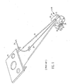
- the suspension comprises a load beam 10 and a flexure 12 located at the end of load beam 10.
- the suspension is attached to the disk file actuator arm (not shown) by means of a mounting plate 14.
- the slider 16 is a conventional slider formed of ceramic material, such as a mixture of alumina (Al2O3) and titanium carbide (TiC).
- the slider 16 has an air bearing surface 18, which includes two rails 20, 22, a back side 24 opposite and generally parallel to air bearing surface 18, a leading edge 25 and a trailing edge 26, both of which form end faces oriented generally perpendicular to air bearing surface 18 and back side 24.
- Slider 16 is secured to flexure 12 by an epoxy bond between back side 24 and flexure 12.
- Located on the trailing edge 26 of slider 16 are two thin film read/write transducers 28, 30.
- multiple thin film transducers are formed on a single slider, even though only one transducer is active as a read/write element, in order to improve the yield of the slider during the thin film fabrication process.
- the transducers 28, 30 have pole tips 29, 31, respectively, which extend toward the edge of respective rails 20, 22.
- Transducer 28 has electrical leads 33, 35 and transducer 30 electrical leads 37, 39 for connection to the read/write electronics of the disk file.
- the electrical attachment to the read/write electronics is made by twisted wires 34 which extend from the read/write electronics, through a tube 36 on load beam 10 and out the end of tube 36.
- the ends of wires 34 are soldered or ultrasonically bonded to the leads 33, 35 of active transducer 28.
- the electrical connection of the transducer 28 by means of the twisted wires 34 is made by manual fabrication.
- the slider-suspension assembly of the present invention is illustrated as slider 16 which is both mechanically and electrically connected to a composite or laminated suspension 40.
- the suspension 40 comprises a nonconductive base layer 42, a patterned conductive layer 44, and an insulating cover layer 48.
- the base layer 42 may be a polyimide sheet and the patterned conductive layer 44 a vapor-deposited copper film.
- the insulating cover layer 48 may be a layer of polyimide formed over the patterned conductive layer 44 and bonded to the base layer 42.
- the patterned conductive layer 44 is thus formed between base layer 42 and cover layer 48 and is visible in Fig. 2 because of the translucency of cover layer 48.
- the electrical leads 46 form part of the conductive layer 44 and extend beneath the slider 16 where they end at terminations 47.
- the conductive pattern of layer 44 is better illustrated in Fig. 3 and includes electrical leads 46 with terminations 47, and large area portions 52, 54 which form a supporting base for the mechanical attachment of the slider in the manner to be described below.
- the slider 16 (Fig. 2) has an air bearing surface 18, including rails 20, 22, and a trailing edge 26.
- Conventional thin film transducers 11, 13 are formed on the trailing edge with respective pole tips 15, 17 extending to the edges of rails 20, 22 respectively.
- Each of transducers 11, 13 has a pair of electrical leads 19, 21 and 27, 29, respectively, extending across the trailing edge 26 toward the corner formed by back side 24 and trailing edge 26.
- slider 16 is mechanically bonded to the large area portions 52, 54 of conductive pattern 44 by means of reflowed solder balls 60 between the slider back side 24 and the conductive layer 44.
- Transducer 11 is the active transducer and electrical connection of it to the terminations 47 formed as part of the conductive pattern 44 is made through generally right-angled solder joints 86.
- the leads 27, 29 of inactive transducer 13 are connected to extensions 49 of portion 52 of the conductive pattern 44.
- Circular openings 60 define a pattern of solder-wettable regions on suspension 40 for mechanical attachment of slider 16.
- Circular openings 61, 63 define a row of solder-wettable regions along the line where the transducer lead terminations will be located when the slider is attached to the suspension.
- the solder-wettable regions 63 are used for electrical connection of leads 46 to transducers 11.
- Fig. 4 illustrates a portion of slider 16 with solder contact pads 70 formed on the back side 24 and solder-wettable regions 60, 63 formed on suspension 40.
- the solder-wettable regions 63 are formed on the terminations 47 of leads 46 (Fig. 3).
- the pattern of solder contact pads 70 formed on the back side 24 of slider 16, only two of which are shown in Fig. 4, is a mirror image of the pattern of solder-wettable regions 60 on portions 52, 54 (Fig. 3).
- Also shown in Fig. 4 is the slider trailing edge 26 with transducer 11 formed thereon, and transducer pole tips 15, lead 21 and lead termination 41.
- each of the contact pads 70 comprises an adhesion film 74 formed directly onto the slider back side 24 and a solder-wettable film 76 formed on the adhesion film 74.
- the solder contact pads are formed on the slider back side by a suitable mask having openings which is placed over back side 24.
- the masked slider is then placed in a evaporation dome and a crucible containing the adhesion material, such as titanium, is evaporated and formed as film 74 on the slider back side 24. Thereafter the solder-wettable film, such as nickel, is evaporated onto the adhesion film.
- solder contact pads 70 provide material which is conducive to the wetting or adhesion of solder and thus permit solder balls to be securely adhered to the back side 24 of slider 16. Chromium may be used in place of titanium as the adhesion film, and copper may be used in place of nickel as the solder-wettable film.
- the solder-wettable regions on suspension 40 are formed by removing selected portions of the polyimide insulating layer 48, which thereby exposes the circular openings 60, 61 on large area portions 52, 54 and the circular openings 63 on lead terminations 47.
- These openings in the polyimide layer are preferably formed by the use of a conventional mask having the pattern of circles.
- the polyimide is then etched away to expose the underlying copper material, as best shown in Fig. 4.
- solder balls 80 are formed on the solder-wettable regions 60 and solder balls 82 are formed on solder-wettable regions 61, 63.
- the solder balls are preferably formed by first tightly securing a mask with circular openings over the suspension, the openings being aligned with the etched-away portions of layer 48. A solder paste is then spread over the mask and forced through the openings. The mask is removed and the solder heated to reflow as solder balls 80, 82. The solder balls are then adhered to the regions 60, 61 and 63 of the patterned conductive layer 44.
- solder balls 80, 82 may also be formed on the suspension by evaporating solder through openings in a mask placed over insulating layer 48, removing the mask and thereafter heating the evaporated solder to cause the solder to reflow as solder balls 80, 82.
- Fig. 5 also illustrates solder balls 84 formed on transducer lead terminations 41.
- the solder balls 84 are formed on all of the thin film transducers at the wafer level during fabrication of the thin film transducers by evaporating solder through a mask placed over the wafer before the wafer is cut into the individual sliders.
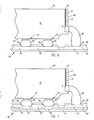
- Fig. 5 thus illustrates an intermediate step in the method for simultaneously mechanically and electrically attaching the slider to the suspension.
- the slider 16 is located on solder balls 80 with the solder balls 80 being in registration between solder contact pads 70 and solder-wettable regions 60.
- Solder balls 84 on the slider trailing edge 26 are aligned with but out of contact with the corresponding row of solder balls 82 on the suspension.
- solder balls 80 With the slider supported in this position heat is then applied to all of the solder balls. This causes solder balls 80 to collapse, thereby permitting solder balls 82, 84 to come into contact and flow together to form generally right-angled solder joints 86 for providing the required electrical connection between transducer 11 and leads 46.
- the right-angle joints 86 formed on inactive transducer 13 provide electrical connection to conductive portion 52 and thus to slider 16.
- Fig. 6 shows the collapsed solder balls 80 and the joined solder balls 82, 84 forming the right angled solder joints 86.
- the slider is both mechanically attached to the suspension and the transducer leads 19, 21 are electrically connected to the electrical leads 46 formed on the suspension.
- the slider 16 is mechanically attached to the conductive layer 44 by the electrically conductive solder balls 80, an electrical path is provided for static discharge from the slider 16, thereby preventing destruction of transducer 11 caused by discharge through the pole tip 15 to the disk surface.
- the area 54 of conductive layer 44 includes a ground lead portion 55 which extends back for grounding connection to the actuator arm (not shown).
- inactive transducer 13 (Fig. 2) provide electrical connection from pole tips 17 to extensions 49 on conductive portion 52 and the reflowed solder balls 80 on portion 52.
- Conductive portion 52 in turn is electrically connected to slider 16 by reflowed solder balls 80, and slider 16 is grounded by path 55 to the actuator arm (not shown).
- solder balls 80 are first formed onto the solder-wettable regions 60, 61 and 63 of the suspension 40.
- the solder balls 80 could instead be first formed onto the solder contact pads 70 on the slider 16.
- solder paste rather than spreading solder paste through a mask or evaporating solder through a mask onto either the slider back side 24 or the suspension 40, it is also possible to spread commercially available preformed solder balls over a mask to locate the solder balls through openings in the mask and then heat the preformed solder balls. The solder balls would then be formed and adhered to either the slider back side or the suspension and the mask would then be removed.
- solder-wettable regions are first formed on the stainless steel flexure. This may be accomplished by any known method of forming, on the stainless steel, metal films which are adherent to solder, and thereafter evaporating or otherwise forming solder onto the metal films formed on the stainless steel flexure.
- the pattern of solder-wettable regions 60 could be formed on a stainless steel flexure by electroplating copper. If the slider is mechanically attached to the stainless steel suspension in this manner, then the electrical connection of the transducer can be made through the use of conventional twisted wires as previously described.
- the composite suspension 40 now includes an underlying support layer 43, which may be a stainless steel flexure, onto which the base layer 42 is adhered. Portions of nonconductive base layer 42 are etched away in the areas 83 where solder balls 82 are to be aligned. Thus, when the copper layer 44 is formed it is placed in direct contact with stainless steel in the areas 83. This allows solder balls 80 to form both a mechanical connection and an electrical grounding path to the stainless steel support layer 43.
- an underlying support layer 43 which may be a stainless steel flexure
- solder may be any type with a melting point compatible with the other materials used in the slider-suspension assembly.
- eutectic tin-bismuth (SnBi) or eutectic tin-lead (SnPb) solder is acceptable.
- the slider contact pads be approximately aligned with their corresponding solderwettable regions prior to reflow.
- the solder balls will be wetted to both the contact pads and the corresponding solder-wettable regions and will cause the slider to be precisely aligned on the suspension.
- the solder balls used to mechanically attach the slider result in the slider back side and suspension being generally parallel because any variations in size among solder balls is averaged out by the relatively large number of solder balls used.
- the slider may be mounted to the suspension with a slight pitch or roll, thereby eliminating the need to preform the flexure.
Landscapes
- Engineering & Computer Science (AREA)
- Manufacturing & Machinery (AREA)
- Adjustment Of The Magnetic Head Position Track Following On Tapes (AREA)
- Supporting Of Heads In Record-Carrier Devices (AREA)
- Connections Effected By Soldering, Adhesion, Or Permanent Deformation (AREA)
Applications Claiming Priority (2)
| Application Number | Priority Date | Filing Date | Title |
|---|---|---|---|
| US923932 | 1986-10-28 | ||
| US06/923,932 US4761699A (en) | 1986-10-28 | 1986-10-28 | Slider-suspension assembly and method for attaching a slider to a suspension in a data recording disk file |
Publications (3)
| Publication Number | Publication Date |
|---|---|
| EP0265720A2 true EP0265720A2 (fr) | 1988-05-04 |
| EP0265720A3 EP0265720A3 (en) | 1989-03-08 |
| EP0265720B1 EP0265720B1 (fr) | 1992-04-15 |
Family
ID=25449489
Family Applications (1)
| Application Number | Title | Priority Date | Filing Date |
|---|---|---|---|
| EP87114569A Expired - Lifetime EP0265720B1 (fr) | 1986-10-28 | 1987-10-06 | Ensemble de glisseur et sa suspension et méthode de fixation d'un glisseur à une suspension dans une unité de disques d'enregistrement de données |
Country Status (4)
| Country | Link |
|---|---|
| US (1) | US4761699A (fr) |
| EP (1) | EP0265720B1 (fr) |
| JP (1) | JPS63113917A (fr) |
| DE (1) | DE3778290D1 (fr) |
Cited By (14)
| Publication number | Priority date | Publication date | Assignee | Title |
|---|---|---|---|---|
| EP0651376A1 (fr) * | 1993-10-29 | 1995-05-03 | Commissariat A L'energie Atomique | Patin de vol à plots de soudures composites et procédé de réalisation |
| WO1995013612A1 (fr) * | 1993-11-12 | 1995-05-18 | Conner Peripherals, Inc. | Regulation de la geometrie de la coulisse d'une tete a haute temperature destinee a l'enregistrement par contact ou quasi contact |
| EP0671727A1 (fr) * | 1994-03-08 | 1995-09-13 | Fujitsu Limited | Unité de disques magnétiques |
| GB2292826A (en) * | 1994-09-01 | 1996-03-06 | Tdk Corp | A grounded magnetic head support |
| EP0726562A3 (fr) * | 1995-02-10 | 1997-02-26 | Masaaki Matsui | Procédé de liaison d'un élément de tête magnétique avec une poutre de support |
| WO1997035303A1 (fr) * | 1996-03-19 | 1997-09-25 | International Business Machines Corporation | Dispositif d'ecartement ajustable a perles de soudure pour accessoire de suspension a glissiere |
| WO1997041554A1 (fr) * | 1996-05-01 | 1997-11-06 | International Business Machines Corporation | Protection de tetes magnetiques contre la decharge electrostatique |
| EP0517198B1 (fr) * | 1991-06-07 | 1999-01-27 | Sharp Kabushiki Kaisha | Tête magnétique à films minces et procédés de fabrication |
| US6008968A (en) * | 1993-10-29 | 1999-12-28 | Commissariat A L'energie Atomique | Slider having composite welding studs and production process |
| US6021022A (en) * | 1997-10-27 | 2000-02-01 | Seagate Technology, Inc. | Flexure displacement limiter-flex circuit interconnect |
| CN1063563C (zh) * | 1994-05-19 | 2001-03-21 | 国际商业机器公司 | 制造信息存储系统的滑块-悬体的方法 |
| CN1084510C (zh) * | 1996-05-01 | 2002-05-08 | 国际商业机器公司 | 磁存储系统中磁头的静电放电保护方法 |
| EP1484750A1 (fr) * | 1992-11-27 | 2004-12-08 | Fujitsu Limited | Mécanisme de support de tête magnétique |
| EP0911809A3 (fr) * | 1992-01-20 | 2006-11-15 | Fujitsu Limited | Ensemble tête magnétique, sa production, et unité de disque magnétique |
Families Citing this family (150)
| Publication number | Priority date | Publication date | Assignee | Title |
|---|---|---|---|---|
| US4975795A (en) * | 1987-12-04 | 1990-12-04 | Digital Equipment Corporation | Electrical connection for a self-loading head assembly for disk drives |
| US5006946A (en) * | 1989-04-19 | 1991-04-09 | Tdk Corporation | Flexible polymeric resinous magnetic head supporting device |
| US5001583A (en) * | 1989-04-19 | 1991-03-19 | Tdk Corporation | Flexible polymeric resinous magnetic head supporting device |
| JP2713762B2 (ja) * | 1989-05-03 | 1998-02-16 | ティーディーケイ株式会社 | ヘッド支持装置 |
| US5166846A (en) * | 1989-05-25 | 1992-11-24 | Sony Corporation | Magnetic head with shielded mounting |
| JP2815176B2 (ja) * | 1989-06-08 | 1998-10-27 | ティーディーケイ株式会社 | スライダ,ヘッド及び記録再生装置 |
| JP2637823B2 (ja) * | 1989-06-08 | 1997-08-06 | ティーディーケイ株式会社 | 磁気ヘッド |
| US6600631B1 (en) | 1989-11-27 | 2003-07-29 | Censtor Corp. | Transducer/flexure/conductor structure for electromagnetic read/write system |
| US5103359A (en) * | 1990-02-05 | 1992-04-07 | Maxtor Corporation | Connector apparatus for electrically coupling a transducer to the electronics of a magnetic recording system |
| US5121273A (en) * | 1990-04-12 | 1992-06-09 | Micropolis Corporation | Computer disk head interconnect assembly |
| US5142425A (en) * | 1990-08-09 | 1992-08-25 | Hewlett-Packard Company | Disk drive in which magnetic head-to-disk capacitive coupling is eliminated |
| JPH04106714A (ja) * | 1990-08-28 | 1992-04-08 | Mitsubishi Electric Corp | 磁気ヘッドの製造方法 |
| US5074029A (en) * | 1990-10-02 | 1991-12-24 | International Business Machines Corporation | Method for stringing wire on an actuator arm |
| US5156710A (en) * | 1991-05-06 | 1992-10-20 | International Business Machines Corporation | Method of laminating polyimide to thin sheet metal |
| CA2090708A1 (fr) * | 1992-04-30 | 1993-10-31 | Jeffrey Merritt Mckay | Combine transducteur-curseur-suspension et sa methode de fabrication |
| US5327310A (en) * | 1992-06-25 | 1994-07-05 | Read-Rite Corporation | Thin film contact recording head |
| US5303096A (en) * | 1992-07-14 | 1994-04-12 | International Business Machines Corporation | Merging of heads into disk drives using low melting wax |
| JPH0619117U (ja) * | 1992-07-31 | 1994-03-11 | ミツミ電機株式会社 | フロッピーディスクドライブ用磁気ヘッド |
| US6341415B2 (en) | 1992-08-31 | 2002-01-29 | Fujitsu Limited | Method for assembling a magnetic head assembly and magnetic disk drive using bonding balls connecting magnetic head terminals to wiring terminals |
| US5644450A (en) * | 1992-10-30 | 1997-07-01 | Fujitsu Limited | Magnetic head assembly with thin-film magnetic head and flexible support member |
| US6084743A (en) * | 1992-12-14 | 2000-07-04 | Maxtor Corporation | Magnetic recorder apparatus with reduced debris accumlation on the recorder head and slider |
| US6188546B1 (en) * | 1993-03-31 | 2001-02-13 | Hitachi, Ltd. | Method of electrically connecting a magnetic head, a magnetic head body and a magnetic disc apparatus |
| US5320272A (en) * | 1993-04-02 | 1994-06-14 | Motorola, Inc. | Tin-bismuth solder connection having improved high temperature properties, and process for forming same |
| US5316205A (en) * | 1993-04-05 | 1994-05-31 | Motorola, Inc. | Method for forming gold bump connection using tin-bismuth solder |
| US5787570A (en) * | 1993-07-08 | 1998-08-04 | Martronics, Inc. | Load distribution measurement and adjustment device |
| US5901014A (en) * | 1993-08-10 | 1999-05-04 | Fujitsu Limited | Thin film magnetic head and assembly configured to reduce risk of discharge between the coil and the core slider |
| KR950020658A (ko) * | 1993-12-07 | 1995-07-24 | 새끼자와 다다시 | 자기디스크장치 |
| US6801398B1 (en) * | 1993-12-10 | 2004-10-05 | Fujitsu Limited | Magnetic head suspension assembly with adhesion limiting structure |
| US5465186A (en) * | 1994-01-26 | 1995-11-07 | International Business Machines Corporation | Shorted magnetoresistive head leads for electrical overstress and electrostatic discharge protection during manufacture of a magnetic storage system |
| US5955176A (en) * | 1994-03-15 | 1999-09-21 | International Business Machines Corporation | Integrated suspension using a high strength conductive material |
| US5781379A (en) * | 1994-03-15 | 1998-07-14 | International Business Machines Corporation | Single beam flexure for a head gimbal assembly |
| US6282064B1 (en) | 1994-03-15 | 2001-08-28 | International Business Machines Corporation | Head gimbal assembly with integrated electrical conductors |
| US6351348B1 (en) | 1994-03-15 | 2002-02-26 | International Business Machines Corporation | Minimal stiffness conductors for a head gimbal assembly |
| TW307863B (fr) * | 1994-03-15 | 1997-06-11 | Ibm | |
| US6282061B1 (en) * | 1994-03-17 | 2001-08-28 | Fujitsu Limited | Magnetic head with improved floating surface |
| JPH07262540A (ja) * | 1994-03-17 | 1995-10-13 | Fujitsu Ltd | 磁気ディスク装置のアクチュエータアームアセンブリ |
| US5761001A (en) * | 1994-03-31 | 1998-06-02 | Nec Corporation | Magnetic head assembly and a magnetic disk apparatus using the same |
| US5839193A (en) * | 1994-04-15 | 1998-11-24 | Hutchinson Technology Incorporated | Method of making laminated structures for a disk drive suspension assembly |
| US5491597A (en) * | 1994-04-15 | 1996-02-13 | Hutchinson Technology Incorporated | Gimbal flexure and electrical interconnect assembly |
| JP2955829B2 (ja) | 1994-04-15 | 1999-10-04 | ハッチンソン テクノロジー インコーポレイテッド | ヘッドサスペンション |
| US5598307A (en) * | 1994-04-15 | 1997-01-28 | Hutchinson Technology Inc. | Integrated gimbal suspension assembly |
| US5815347A (en) * | 1994-05-19 | 1998-09-29 | International Business Machines Corporation | Information storage system having an improved planar head-suspension assembly |
| US5680274A (en) * | 1994-06-27 | 1997-10-21 | International Business Machines Corporation | Integrated suspension for an information storage system having electrostatic discharge protection |
| US5623383A (en) * | 1994-06-30 | 1997-04-22 | International Business Machines | Magnetic slider design for precision wear-in |
| WO1996001470A1 (fr) * | 1994-07-06 | 1996-01-18 | Intégral Peripherals, Inc. | Curseur a palier d'air et element de suspension de tete ameliores |
| JP2855254B2 (ja) * | 1994-07-15 | 1999-02-10 | 日本メクトロン株式会社 | 回路配線を備えた磁気ヘッド用サスペンションの製造法 |
| US6233117B1 (en) * | 1994-07-15 | 2001-05-15 | Seagate Technology Llc | Electrically conductive path between head assembly and gimbal assembly in magnetic disc drive |
| JP2855255B2 (ja) * | 1994-07-26 | 1999-02-10 | 日本メクトロン株式会社 | 磁気ヘッド用サスペンション及びその製造法 |
| JP3329953B2 (ja) * | 1994-09-16 | 2002-09-30 | インターナショナル・ビジネス・マシーンズ・コーポレーション | ヘッドアクチュエータ |
| EP0707310A1 (fr) | 1994-10-12 | 1996-04-17 | Hewlett-Packard Company | Ensemble de suspension de tête pourvu de ressorts à cardan portant couplés en parallèle |
| US5539596A (en) * | 1994-12-29 | 1996-07-23 | International Business Machines Corporation | Integrated suspension, actuator arm and coil assembly with common structural support layer |
| JP2855414B2 (ja) * | 1995-04-13 | 1999-02-10 | 日本メクトロン株式会社 | 磁気ヘッド用中継基板及びその製造法 |
| JPH08315343A (ja) * | 1995-05-16 | 1996-11-29 | Hitachi Ltd | 磁気ヘッド組立体およびその組立方法及びその組立装置並びに磁気ディスク装置 |
| US5661896A (en) * | 1995-05-19 | 1997-09-02 | International Business Machines Corporation | Method of manufacturing a termination pad manipulator for a laminated suspension in a data storage system |
| US5650595A (en) * | 1995-05-25 | 1997-07-22 | International Business Machines Corporation | Electronic module with multiple solder dams in soldermask window |
| US5808834A (en) * | 1995-06-07 | 1998-09-15 | Hutchinson Technology Incorporated | Laminated adapter |
| US5835306A (en) * | 1995-06-07 | 1998-11-10 | Hutchinson Technology Incorporated | Integrated gimbal suspension assembly with assymetric bond pad |
| US5608591A (en) * | 1995-06-09 | 1997-03-04 | International Business Machines Corporation | Integrated head-electronics interconnection suspension for a data recording disk drive |
| JPH0935227A (ja) * | 1995-07-21 | 1997-02-07 | Sony Corp | 磁気ヘッド装置 |
| US6219202B1 (en) | 1995-10-26 | 2001-04-17 | International Business Machines Corporation | Slider suspension assembly and method for attaching a slider to a suspension in a data-recording disk file including a flexible integrated cable having an aperture therein for permitting electrical contact |
| US5737152A (en) * | 1995-10-27 | 1998-04-07 | Quantum Corporation | Suspension with multi-layered integrated conductor trace array for optimized electrical parameters |
| US5661618A (en) * | 1995-12-11 | 1997-08-26 | International Business Machines Corporation | Magnetic recording device having a improved slider |
| US5742996A (en) * | 1996-01-03 | 1998-04-28 | International Business Machines Corporation | Method of manufacturing a transducer suspension system |
| US5617274A (en) * | 1996-01-12 | 1997-04-01 | International Business Machines Corporation | Low profile integral flexure for closely packed disks in a disk drive assembly |
| US5883759A (en) * | 1996-02-22 | 1999-03-16 | Seagate Technology, Inc. | Flex circuit head interconnect for improved electrical performance and ease of assembly |
| AU6284696A (en) * | 1996-03-19 | 1997-10-10 | A. David Erpelding | Planar head gimbal assembly for pico/nano slider |
| JP3107746B2 (ja) * | 1996-04-27 | 2000-11-13 | 日本メクトロン株式会社 | 磁気ヘッド用サスペンションの製造法 |
| US5712748A (en) * | 1996-06-11 | 1998-01-27 | Seagate Technology, Inc. | Slider-suspension in a disc drive |
| US5914834A (en) * | 1996-06-17 | 1999-06-22 | Hutchinson Technology, Inc. | Head suspension assembly with electrical interconnect by slider bond pads and gimbal bonding zones |
| US5828031A (en) * | 1996-06-27 | 1998-10-27 | International Business Machines Corporation | Head transducer to suspension lead termination by solder ball place/reflow |
| US6046882A (en) * | 1996-07-11 | 2000-04-04 | International Business Machines Corporation | Solder balltape and method for making electrical connection between a head transducer and an electrical lead |
| US5821494A (en) * | 1996-09-27 | 1998-10-13 | International Business Machines Corporation | Method of electrical connection between head transducer and suspension by solder wire bumping at slider level and laser reflow |
| US5754369A (en) * | 1996-10-03 | 1998-05-19 | Quantum Corporation | Head suspension with self-shielding integrated conductor trace array |
| US5796552A (en) * | 1996-10-03 | 1998-08-18 | Quantum Corporation | Suspension with biaxially shielded conductor trace array |
| US5757585A (en) * | 1996-10-15 | 1998-05-26 | International Business Machines Corporation | Method for bonding leads to a slider in a disk drive integrated suspension assembly |
| US6038102A (en) * | 1997-01-21 | 2000-03-14 | Quantum Corporation | Conductor trace array having interleaved passive conductors |
| US6246548B1 (en) | 1997-03-24 | 2001-06-12 | Maxtor Corporation | Mechanically formed standoffs in a circuit interconnect |
| US5889636A (en) * | 1997-06-12 | 1999-03-30 | International Business Machines Corporation | Electrical connection for slider/suspension assembly |
| US5872687A (en) * | 1997-08-25 | 1999-02-16 | International Business Machines Corporation | Transducer suspension system |
| US5896248A (en) * | 1997-09-05 | 1999-04-20 | Read-Rite Corporation | Bond pads for metal welding of flexure to air bearing slider and grounding configuration thereof |
| US5949618A (en) * | 1997-10-14 | 1999-09-07 | International Business Machines Corporation | Solder bump electrical connection and method for fabrication |
| US6061205A (en) * | 1998-01-30 | 2000-05-09 | Finegan; Joel D. | Slider support assembly and method |
| DE19833388C2 (de) | 1998-07-24 | 2003-05-15 | Ibm | Verfahren zur gezielten Beeinflussung der Schwingungen von fein- bzw. mikromechanischen Träger-Systemen |
| WO2000030080A1 (fr) * | 1998-11-13 | 2000-05-25 | Tdk Corporation | Mecanisme support pour tete d'enregistrement/de reproduction, et dispositif d'enregistrement/de reproduction |
| US6201664B1 (en) | 1998-11-16 | 2001-03-13 | International Business Machines Corporation | Polymer bumps for trace and shock protection |
| US6125015A (en) * | 1998-12-04 | 2000-09-26 | Read-Rite Corporation | Head gimbal assembly with low stiffness flex circuit and ESD Protection |
| US6714384B2 (en) * | 1998-12-07 | 2004-03-30 | Seagate Technology Llc | Reduced stiffness printed circuit head interconnect |
| US6249404B1 (en) | 1999-02-04 | 2001-06-19 | Read-Rite Corporation | Head gimbal assembly with a flexible printed circuit having a serpentine substrate |
| US6711812B1 (en) | 1999-04-13 | 2004-03-30 | Unicap Electronics Industrial Corporation | Method of making metal core substrate printed circuit wiring board enabling thermally enhanced ball grid array (BGA) packages |
| US6675472B1 (en) | 1999-04-29 | 2004-01-13 | Unicap Electronics Industrial Corporation | Process and structure for manufacturing plastic chip carrier |
| US6351353B1 (en) | 1999-06-11 | 2002-02-26 | Seagate Technology, Inc. | Interconnect designs for micromotor, magnetic recording head and suspension assemblies |
| US6650506B1 (en) | 1999-12-15 | 2003-11-18 | Patrick Risse | Double-sided disk storage using a single configuration of magnetoresistive head |
| US7059868B1 (en) | 2000-03-07 | 2006-06-13 | Western Digital (Fremont), Inc. | Connection of trace circuitry in a computer disk drive system |
| US6700748B1 (en) | 2000-04-28 | 2004-03-02 | International Business Machines Corporation | Methods for creating ground paths for ILS |
| JP2002025025A (ja) * | 2000-06-23 | 2002-01-25 | Internatl Business Mach Corp <Ibm> | はんだボール接合装置及びはんだボール接合方法 |
| US6757135B2 (en) | 2000-07-28 | 2004-06-29 | Seagate Technology Llc | Leading edge bond pads |
| WO2002013189A1 (fr) * | 2000-08-09 | 2002-02-14 | Sae Magnetics (H.K.) Ltd. | Plot de connexion pour circuit de suspension |
| JP3656534B2 (ja) | 2000-09-12 | 2005-06-08 | Tdk株式会社 | ヘッドジンバルアセンブリの製造方法及び接続部切断装置 |
| US6965501B1 (en) * | 2000-09-28 | 2005-11-15 | Hitachi Global Storage Technologies, The Netherlands B.V. | Integrated lead suspension for high density drive |
| US20020057531A1 (en) * | 2000-11-15 | 2002-05-16 | Seagate Technology Llc | HGA ballbond assembly with wafer process assembly features |
| US6894879B2 (en) * | 2000-12-15 | 2005-05-17 | Seagate Technology Llc | Disc drive shunting device |
| US6522504B1 (en) * | 2001-01-31 | 2003-02-18 | Western Digital Technologies, Inc. | Head stack assembly and disk drive using a reversed direction head gimbal assembly |
| US6523250B2 (en) | 2001-03-21 | 2003-02-25 | International Business Machines Corporation | Method of attaching a slider with head transducer to a suspension |
| JP3634773B2 (ja) * | 2001-06-08 | 2005-03-30 | アルプス電気株式会社 | 磁気ヘッド及びその製造方法 |
| US6756287B2 (en) | 2001-07-16 | 2004-06-29 | Seagate Technology Llc | Laser-assisted slicing of notched wafer |
| US7289302B1 (en) | 2001-10-04 | 2007-10-30 | Maxtor Corporation | On slider inductors and capacitors to reduce electrostatic discharge damage |
| US6865058B2 (en) | 2001-11-05 | 2005-03-08 | Seagate Technology Llc | Load beam attachment to actuator arm |
| US7307816B1 (en) | 2001-12-21 | 2007-12-11 | Western Digital (Fremont), Llc | Flexure design and assembly process for attachment of slider using solder and laser reflow |
| US6796018B1 (en) | 2001-12-21 | 2004-09-28 | Western Digital (Fremont), Inc. | Method of forming a slider/suspension assembly |
| CN1273958C (zh) * | 2002-01-17 | 2006-09-06 | 新科实业有限公司 | Fpc设计和hga组装方法 |
| US6801400B2 (en) * | 2002-01-24 | 2004-10-05 | Hitachi Global Storage Technologies, The Netherlands B.V. | Motion limiter for disk drive integrated gimbal suspension |
| US6778360B2 (en) * | 2002-04-11 | 2004-08-17 | Hitachi Global Storage Technologies Netherlands B.V. | Electrostatic discharge device in a disk drive providing a conductive path between a slider and the disk drive housing thereby protecting against electrostatic discharge |
| US6833978B2 (en) * | 2002-04-24 | 2004-12-21 | Hitachi Global Storage Technologies | Micro-actuator integrated lead suspension head terminations |
| US7369370B2 (en) | 2002-08-07 | 2008-05-06 | Headway Technologies, Inc. | GMR head design that suppresses tribocharge during its assembly |
| US6870706B1 (en) | 2002-08-07 | 2005-03-22 | Headway Technologies, Inc. | Method for suppressing tribocharge in the assembly of magnetic heads |
| JP2004152393A (ja) * | 2002-10-30 | 2004-05-27 | Toshiba Corp | アームアッセンブリとこのアームアッセンブリを備える記憶装置及び記憶装置の製造方法 |
| WO2004066279A1 (fr) * | 2003-01-20 | 2004-08-05 | Sae Magnetics (H.K.) Ltd. | Systeme et procede de fabrication de bras de lecteur de disque dur et liaison de tete magnetique a une suspension sur un bras de lecteur. |
| US7681302B2 (en) * | 2003-01-27 | 2010-03-23 | Sae Magnetics (H. K.) Ltd. | Method for manufacturing a hard disk drive arm |
| JP3940688B2 (ja) * | 2003-03-20 | 2007-07-04 | Tdk株式会社 | ヘッドスライダ、ヘッドジンバルアセンブリ及びハードディスク装置 |
| US7212381B2 (en) * | 2003-08-14 | 2007-05-01 | Seagate Technology Llc | Slider having adjusted transducer recession and method of adjusting recession |
| JP2005149574A (ja) * | 2003-11-12 | 2005-06-09 | Shinka Jitsugyo Kk | 磁気ディスクドライブ装置及び磁気ディスクドライブ装置の製造方法 |
| US7384531B1 (en) * | 2004-02-19 | 2008-06-10 | Hutchinson Technology Incorporated | Plated ground features for integrated lead suspensions |
| JP4255859B2 (ja) * | 2004-02-26 | 2009-04-15 | ヒタチグローバルストレージテクノロジーズネザーランドビーブイ | 回転円板形記憶装置及び配線一体型ヘッド・サスペンション・アセンブリ |
| US7535676B2 (en) * | 2004-08-26 | 2009-05-19 | Hitachi Global Storage Technologies B.V. | Slider with bonding pads opposite the air bearing surface |
| US7218478B2 (en) * | 2004-09-28 | 2007-05-15 | Hitachi Global Storage Technologies Netherlands B.V. | Disk drive with negative-pitch slider having protrusion pad contacting the disk when the disk is rotating at operating speed |
| US20060087768A1 (en) * | 2004-10-26 | 2006-04-27 | Erpelding A D | Method and apparatus for electrically coupling a slider to a wireless suspension substrate |
| US7929248B2 (en) * | 2006-05-23 | 2011-04-19 | Seagate Technology Llc | Top bond pad for transducing head interconnect |
| JP2008065878A (ja) * | 2006-09-05 | 2008-03-21 | Hitachi Global Storage Technologies Netherlands Bv | 磁気スライダとヘッド・ジンバル・アセンブリ及びその製造方法 |
| US7875804B1 (en) | 2006-09-27 | 2011-01-25 | Hutchinson Technology Incorporated | Plated ground features for integrated lead suspensions |
| CN101241707A (zh) * | 2007-02-07 | 2008-08-13 | 新科实业有限公司 | 具有静电防护结构的柔性装配磁头、磁头折片组合及磁盘驱动单元 |
| US7744306B2 (en) * | 2007-04-02 | 2010-06-29 | Greer Robert F | Preformed thermoplastic indicia for airport runways and taxiways |
| US7952833B2 (en) * | 2007-10-01 | 2011-05-31 | Seagate Technology Llc | High density electrical interconnect assembly |
| US8213121B2 (en) * | 2007-10-09 | 2012-07-03 | Hitachi Global Storage Technologies, Netherlands B.V. | HGA suspension pad barrier for elimination of solder bridging defect |
| US20090168247A1 (en) * | 2007-12-28 | 2009-07-02 | Christian Rene Bonhote | Magnetic head with embedded solder connection and method for manufacture thereof |
| US8243395B2 (en) * | 2008-09-18 | 2012-08-14 | Hitachi Global Storage Technologies, Netherlands B.V. | Method of utilizing a solder reflow channel in the formation of a hard disk drive |
| US8054584B2 (en) * | 2008-11-26 | 2011-11-08 | Seagate Technology Llc | Top bond pad bias and variation control |
| US8218268B1 (en) | 2009-05-27 | 2012-07-10 | Western Digital Technologies, Inc. | Head gimbal assembly having a load beam aperature over conductive heating pads that are offset from head bonding pads |
| US8400736B2 (en) * | 2009-07-27 | 2013-03-19 | Seagate Technology, Llc | Slider top bond design with shorted pad configuration |
| US8164858B1 (en) | 2009-11-04 | 2012-04-24 | Western Digital (Fremont), Llc | Read head having conductive filler in insulated hole through substrate |
| US8934200B2 (en) | 2012-04-25 | 2015-01-13 | Seagate Technology Llc | Flex circuit having a multiple layered structure and interconnect |
| US9013963B2 (en) | 2012-04-25 | 2015-04-21 | Seagate Technology Llc | Flex circuit with dual sided interconnect structure |
| US8730621B2 (en) | 2012-07-09 | 2014-05-20 | Seagate Technology Llc | Solder ball bridge, and methods of making |
| US8902547B1 (en) * | 2013-07-08 | 2014-12-02 | Seagate Technology Llc | Multiple layered head interconnect structure |
| US9135935B1 (en) * | 2013-10-11 | 2015-09-15 | Western Digital Technologies, Inc. | Customized head gimbal assembly bonding skew angle for adjusting two-dimensional magnetic recording reader alignment |
| US9105288B1 (en) * | 2014-03-11 | 2015-08-11 | Magnecomp Corporation | Formed electrical contact pad for use in a dual stage actuated suspension |
| US11062731B1 (en) * | 2020-05-11 | 2021-07-13 | Western Digital Technologies, Inc. | Solder bump height stabilization for micro and fine pitch electrode pads |
| US11355144B1 (en) * | 2021-05-11 | 2022-06-07 | Seagate Technology Llc | Mounting supports that create a bond pad gap for a hard disk slider |
| US11631426B1 (en) * | 2021-12-15 | 2023-04-18 | Western Digital Technologies, Inc. | Hard disk drive suspension pad peel-prevention configuration |
| US11705153B1 (en) * | 2022-03-23 | 2023-07-18 | Western Digital Technologies, Inc. | Hard disk drive suspension pad pre-solder formation and guiding |
| US12361966B2 (en) * | 2023-06-26 | 2025-07-15 | Western Digital Technologies, Inc. | Pre-solder bump preventive overcoating |
Family Cites Families (11)
| Publication number | Priority date | Publication date | Assignee | Title |
|---|---|---|---|---|
| US3564522A (en) * | 1966-12-16 | 1971-02-16 | Data Disc Inc | Transducer with thin film coil and semiconductor switching |
| JPS5511919B2 (fr) * | 1973-11-30 | 1980-03-28 | ||
| JPS51104787A (ja) * | 1975-03-12 | 1976-09-16 | Kyoshi Okano | Nenseiryutaifuiidosochi |
| JPS51144746A (en) * | 1975-06-05 | 1976-12-13 | Riken Vitamin Oil Co Ltd | Production of instant mochi |
| JPS51151115A (en) * | 1975-06-20 | 1976-12-25 | Hitachi Ltd | Manufacturing method of thin film integrated magnetic head |
| JPS5931128B2 (ja) * | 1975-07-14 | 1984-07-31 | 株式会社日立製作所 | 浮動形磁気ヘツド |
| FR2384315A1 (fr) * | 1977-03-18 | 1978-10-13 | Cii Honeywell Bull | Plate-forme comportant au moins un transducteur integre et procede de fabrication de ladite plate-forme |
| JPS5926278B2 (ja) * | 1977-05-30 | 1984-06-26 | 三菱化学株式会社 | 既知塩基配列オリゴヌクレオチドの酵素的製造法 |
| DE3173078D1 (en) * | 1981-12-29 | 1986-01-09 | Ibm | Soldering method of pins to eyelets of conductors formed on a ceramic substrate |
| US4546541A (en) * | 1983-10-14 | 1985-10-15 | Applied Magnetics Corporation | Method of attaching electrical conductors to thin film magnetic transducer |
| JPS61144712A (ja) * | 1984-12-18 | 1986-07-02 | Canon Electronics Inc | 磁気ヘツド |
-
1986
- 1986-10-28 US US06/923,932 patent/US4761699A/en not_active Expired - Lifetime
-
1987
- 1987-05-18 JP JP62119164A patent/JPS63113917A/ja active Pending
- 1987-10-06 EP EP87114569A patent/EP0265720B1/fr not_active Expired - Lifetime
- 1987-10-06 DE DE8787114569T patent/DE3778290D1/de not_active Expired - Lifetime
Cited By (22)
| Publication number | Priority date | Publication date | Assignee | Title |
|---|---|---|---|---|
| EP0517198B1 (fr) * | 1991-06-07 | 1999-01-27 | Sharp Kabushiki Kaisha | Tête magnétique à films minces et procédés de fabrication |
| EP0911809A3 (fr) * | 1992-01-20 | 2006-11-15 | Fujitsu Limited | Ensemble tête magnétique, sa production, et unité de disque magnétique |
| US7221541B2 (en) | 1992-11-27 | 2007-05-22 | Fujitsu Limited | Magnetic head supporting mechanism |
| EP1638087A1 (fr) * | 1992-11-27 | 2006-03-22 | Fujitsu Limited | Mécanisme de support de tête magnétique |
| EP1484750A1 (fr) * | 1992-11-27 | 2004-12-08 | Fujitsu Limited | Mécanisme de support de tête magnétique |
| US6008968A (en) * | 1993-10-29 | 1999-12-28 | Commissariat A L'energie Atomique | Slider having composite welding studs and production process |
| FR2711830A1 (fr) * | 1993-10-29 | 1995-05-05 | Commissariat Energie Atomique | Assemblage patin de vol/bras-ressort à plots de soudures composités et procédé de réalisation. |
| EP0651376A1 (fr) * | 1993-10-29 | 1995-05-03 | Commissariat A L'energie Atomique | Patin de vol à plots de soudures composites et procédé de réalisation |
| US6098270A (en) * | 1993-10-29 | 2000-08-08 | Commissariat A L'energie Atomique | Process for producing a slider having composite welding studs |
| WO1995013612A1 (fr) * | 1993-11-12 | 1995-05-18 | Conner Peripherals, Inc. | Regulation de la geometrie de la coulisse d'une tete a haute temperature destinee a l'enregistrement par contact ou quasi contact |
| EP0671727A1 (fr) * | 1994-03-08 | 1995-09-13 | Fujitsu Limited | Unité de disques magnétiques |
| US5786964A (en) * | 1994-03-08 | 1998-07-28 | Fujitsu Limited | Magnetic disk drive unit with improved signal feeding and extracting arrangement |
| CN1063563C (zh) * | 1994-05-19 | 2001-03-21 | 国际商业机器公司 | 制造信息存储系统的滑块-悬体的方法 |
| GB2292826B (en) * | 1994-09-01 | 1996-09-11 | Tdk Corp | A magnetic head supporting apparatus |
| GB2292826A (en) * | 1994-09-01 | 1996-03-06 | Tdk Corp | A grounded magnetic head support |
| EP0726562A3 (fr) * | 1995-02-10 | 1997-02-26 | Masaaki Matsui | Procédé de liaison d'un élément de tête magnétique avec une poutre de support |
| US5680275A (en) * | 1996-03-19 | 1997-10-21 | International Business Machines Corporation | Adjustable solder bump spacer for slider-suspension attachment |
| CN1093673C (zh) * | 1996-03-19 | 2002-10-30 | 国际商业机器公司 | 用于磁盘系统的滑块/悬架组件及滑块与悬架间距控制方法 |
| WO1997035303A1 (fr) * | 1996-03-19 | 1997-09-25 | International Business Machines Corporation | Dispositif d'ecartement ajustable a perles de soudure pour accessoire de suspension a glissiere |
| WO1997041554A1 (fr) * | 1996-05-01 | 1997-11-06 | International Business Machines Corporation | Protection de tetes magnetiques contre la decharge electrostatique |
| CN1084510C (zh) * | 1996-05-01 | 2002-05-08 | 国际商业机器公司 | 磁存储系统中磁头的静电放电保护方法 |
| US6021022A (en) * | 1997-10-27 | 2000-02-01 | Seagate Technology, Inc. | Flexure displacement limiter-flex circuit interconnect |
Also Published As
| Publication number | Publication date |
|---|---|
| JPS63113917A (ja) | 1988-05-18 |
| DE3778290D1 (de) | 1992-05-21 |
| US4761699A (en) | 1988-08-02 |
| EP0265720A3 (en) | 1989-03-08 |
| EP0265720B1 (fr) | 1992-04-15 |
Similar Documents
| Publication | Publication Date | Title |
|---|---|---|
| US4761699A (en) | Slider-suspension assembly and method for attaching a slider to a suspension in a data recording disk file | |
| US5872687A (en) | Transducer suspension system | |
| EP0683491B1 (fr) | Connection soudée de tête de transducteur | |
| EP0888610B1 (fr) | Dispositif d'ecartement ajustable a perles de soudure pour accessoire de suspension a glissiere | |
| US7307816B1 (en) | Flexure design and assembly process for attachment of slider using solder and laser reflow | |
| US5889636A (en) | Electrical connection for slider/suspension assembly | |
| US6796018B1 (en) | Method of forming a slider/suspension assembly | |
| US5821494A (en) | Method of electrical connection between head transducer and suspension by solder wire bumping at slider level and laser reflow | |
| US6442828B1 (en) | Method of manufacturing a transducer suspension system | |
| US6587310B1 (en) | Magnetic head suspension with single layer preshaped trace interconnect | |
| US5844753A (en) | Magnetic head junction board and manufacturing method for the same | |
| EP0649140B1 (fr) | Interconnexion électrique pour un assemblage tête/bras d'un entraínement de disque d'ordinateur | |
| US5914834A (en) | Head suspension assembly with electrical interconnect by slider bond pads and gimbal bonding zones | |
| US6125014A (en) | Via-less connection using interconnect traces between bond pads and a transducer coil of a magnetic head slider | |
| CN1136543C (zh) | 头悬架组件和含有该头悬架组件的数据记录盘驱动器 | |
| US20010039716A1 (en) | Head gimbal assembly with integrated electrical conductors | |
| JPH01129431A (ja) | 半導体チップ実装方式 | |
| US6417997B1 (en) | Mechanically formed standoffs in a circuit interconnect | |
| US5808834A (en) | Laminated adapter | |
| WO1999000874A1 (fr) | Connecteur de circuit | |
| US5712748A (en) | Slider-suspension in a disc drive | |
| US6665151B1 (en) | Flexible tabs for improved microactuator assembly process | |
| JP3247644B2 (ja) | ディスク・ドライブ装置のアーム・アセンブリ及びこれの製造方法 | |
| US20240157457A1 (en) | Process for high density solder interconnect | |
| JP3731731B2 (ja) | 磁気ヘッド装置の製造方法 |
Legal Events
| Date | Code | Title | Description |
|---|---|---|---|
| PUAI | Public reference made under article 153(3) epc to a published international application that has entered the european phase |
Free format text: ORIGINAL CODE: 0009012 |
|
| AK | Designated contracting states |
Kind code of ref document: A2 Designated state(s): DE FR GB IT |
|
| 17P | Request for examination filed |
Effective date: 19880823 |
|
| PUAL | Search report despatched |
Free format text: ORIGINAL CODE: 0009013 |
|
| AK | Designated contracting states |
Kind code of ref document: A3 Designated state(s): DE FR GB IT |
|
| 17Q | First examination report despatched |
Effective date: 19900328 |
|
| GRAA | (expected) grant |
Free format text: ORIGINAL CODE: 0009210 |
|
| AK | Designated contracting states |
Kind code of ref document: B1 Designated state(s): DE FR GB IT |
|
| PG25 | Lapsed in a contracting state [announced via postgrant information from national office to epo] |
Ref country code: IT Free format text: LAPSE BECAUSE OF FAILURE TO SUBMIT A TRANSLATION OF THE DESCRIPTION OR TO PAY THE FEE WITHIN THE PRESCRIBED TIME-LIMIT;WARNING: LAPSES OF ITALIAN PATENTS WITH EFFECTIVE DATE BEFORE 2007 MAY HAVE OCCURRED AT ANY TIME BEFORE 2007. THE CORRECT EFFECTIVE DATE MAY BE DIFFERENT FROM THE ONE RECORDED. Effective date: 19920415 |
|
| REF | Corresponds to: |
Ref document number: 3778290 Country of ref document: DE Date of ref document: 19920521 |
|
| ET | Fr: translation filed | ||
| PLBE | No opposition filed within time limit |
Free format text: ORIGINAL CODE: 0009261 |
|
| STAA | Information on the status of an ep patent application or granted ep patent |
Free format text: STATUS: NO OPPOSITION FILED WITHIN TIME LIMIT |
|
| 26N | No opposition filed | ||
| PGFP | Annual fee paid to national office [announced via postgrant information from national office to epo] |
Ref country code: FR Payment date: 19991018 Year of fee payment: 13 |
|
| PG25 | Lapsed in a contracting state [announced via postgrant information from national office to epo] |
Ref country code: FR Free format text: LAPSE BECAUSE OF NON-PAYMENT OF DUE FEES Effective date: 20010629 |
|
| REG | Reference to a national code |
Ref country code: FR Ref legal event code: ST |
|
| REG | Reference to a national code |
Ref country code: GB Ref legal event code: IF02 |
|
| REG | Reference to a national code |
Ref country code: GB Ref legal event code: 732E |
|
| PGFP | Annual fee paid to national office [announced via postgrant information from national office to epo] |
Ref country code: GB Payment date: 20060925 Year of fee payment: 20 |
|
| PGFP | Annual fee paid to national office [announced via postgrant information from national office to epo] |
Ref country code: DE Payment date: 20061207 Year of fee payment: 20 |
|
| REG | Reference to a national code |
Ref country code: GB Ref legal event code: PE20 |
|
| PG25 | Lapsed in a contracting state [announced via postgrant information from national office to epo] |
Ref country code: GB Free format text: LAPSE BECAUSE OF EXPIRATION OF PROTECTION Effective date: 20071005 |