EP0266027A1 - Maschine zum Umschlagen vorstehender Ränder - Google Patents
Maschine zum Umschlagen vorstehender Ränder Download PDFInfo
- Publication number
- EP0266027A1 EP0266027A1 EP87306914A EP87306914A EP0266027A1 EP 0266027 A1 EP0266027 A1 EP 0266027A1 EP 87306914 A EP87306914 A EP 87306914A EP 87306914 A EP87306914 A EP 87306914A EP 0266027 A1 EP0266027 A1 EP 0266027A1
- Authority
- EP
- European Patent Office
- Prior art keywords
- laminate
- sheet
- blank
- edges
- folding
- Prior art date
- Legal status (The legal status is an assumption and is not a legal conclusion. Google has not performed a legal analysis and makes no representation as to the accuracy of the status listed.)
- Withdrawn
Links
- 239000000853 adhesive Substances 0.000 claims description 9
- 230000001070 adhesive effect Effects 0.000 claims description 9
- 239000011248 coating agent Substances 0.000 claims description 2
- 238000000576 coating method Methods 0.000 claims description 2
- 230000007246 mechanism Effects 0.000 description 34
- 230000000712 assembly Effects 0.000 description 6
- 238000000429 assembly Methods 0.000 description 6
- 238000010030 laminating Methods 0.000 description 3
- 239000004820 Pressure-sensitive adhesive Substances 0.000 description 2
- 230000009471 action Effects 0.000 description 2
- 238000009963 fulling Methods 0.000 description 2
- 239000000463 material Substances 0.000 description 2
- 230000003213 activating effect Effects 0.000 description 1
- 230000004913 activation Effects 0.000 description 1
- 239000012790 adhesive layer Substances 0.000 description 1
- 230000008859 change Effects 0.000 description 1
- 238000010276 construction Methods 0.000 description 1
- 230000008878 coupling Effects 0.000 description 1
- 238000010168 coupling process Methods 0.000 description 1
- 238000005859 coupling reaction Methods 0.000 description 1
- 238000001514 detection method Methods 0.000 description 1
- 238000010586 diagram Methods 0.000 description 1
- 239000010410 layer Substances 0.000 description 1
- 238000004519 manufacturing process Methods 0.000 description 1
- 238000000034 method Methods 0.000 description 1
- 238000003825 pressing Methods 0.000 description 1
- 230000005855 radiation Effects 0.000 description 1
- 230000004044 response Effects 0.000 description 1
Images





Classifications
-
- B—PERFORMING OPERATIONS; TRANSPORTING
- B32—LAYERED PRODUCTS
- B32B—LAYERED PRODUCTS, i.e. PRODUCTS BUILT-UP OF STRATA OF FLAT OR NON-FLAT, e.g. CELLULAR OR HONEYCOMB, FORM
- B32B29/00—Layered products comprising a layer of paper or cardboard
- B32B29/002—Layered products comprising a layer of paper or cardboard as the main or only constituent of a layer, which is next to another layer of the same or of a different material
- B32B29/005—Layered products comprising a layer of paper or cardboard as the main or only constituent of a layer, which is next to another layer of the same or of a different material next to another layer of paper or cardboard layer
-
- B—PERFORMING OPERATIONS; TRANSPORTING
- B31—MAKING ARTICLES OF PAPER, CARDBOARD OR MATERIAL WORKED IN A MANNER ANALOGOUS TO PAPER; WORKING PAPER, CARDBOARD OR MATERIAL WORKED IN A MANNER ANALOGOUS TO PAPER
- B31F—MECHANICAL WORKING OR DEFORMATION OF PAPER, CARDBOARD OR MATERIAL WORKED IN A MANNER ANALOGOUS TO PAPER
- B31F1/00—Mechanical deformation without removing material, e.g. in combination with laminating
- B31F1/0003—Shaping by bending, folding, twisting, straightening, flattening or rim-rolling; Shaping by bending, folding or rim-rolling combined with joining; Apparatus therefor
- B31F1/0006—Bending or folding; Folding edges combined with joining; Reinforcing edges during the folding thereof
- B31F1/0009—Bending or folding; Folding edges combined with joining; Reinforcing edges during the folding thereof of plates, sheets or webs
- B31F1/0019—Bending or folding; Folding edges combined with joining; Reinforcing edges during the folding thereof of plates, sheets or webs the plates, sheets or webs moving continuously
- B31F1/0029—Folding edges; Folding edges combined with joining; Reinforcing edges during the folding thereof, e.g. by introducing a thread; Folding the edges of a sheathing
-
- B—PERFORMING OPERATIONS; TRANSPORTING
- B31—MAKING ARTICLES OF PAPER, CARDBOARD OR MATERIAL WORKED IN A MANNER ANALOGOUS TO PAPER; WORKING PAPER, CARDBOARD OR MATERIAL WORKED IN A MANNER ANALOGOUS TO PAPER
- B31F—MECHANICAL WORKING OR DEFORMATION OF PAPER, CARDBOARD OR MATERIAL WORKED IN A MANNER ANALOGOUS TO PAPER
- B31F1/00—Mechanical deformation without removing material, e.g. in combination with laminating
- B31F1/0003—Shaping by bending, folding, twisting, straightening, flattening or rim-rolling; Shaping by bending, folding or rim-rolling combined with joining; Apparatus therefor
- B31F1/0006—Bending or folding; Folding edges combined with joining; Reinforcing edges during the folding thereof
- B31F1/0009—Bending or folding; Folding edges combined with joining; Reinforcing edges during the folding thereof of plates, sheets or webs
- B31F1/0016—Folding edges; Folding edges combined with joining; Reinforcing edges during the folding thereof, e.g. by introducing a thread; Folding the edges of a sheathing
-
- B—PERFORMING OPERATIONS; TRANSPORTING
- B32—LAYERED PRODUCTS
- B32B—LAYERED PRODUCTS, i.e. PRODUCTS BUILT-UP OF STRATA OF FLAT OR NON-FLAT, e.g. CELLULAR OR HONEYCOMB, FORM
- B32B7/00—Layered products characterised by the relation between layers; Layered products characterised by the relative orientation of features between layers, or by the relative values of a measurable parameter between layers, i.e. products comprising layers having different physical, chemical or physicochemical properties; Layered products characterised by the interconnection of layers
- B32B7/04—Interconnection of layers
- B32B7/12—Interconnection of layers using interposed adhesives or interposed materials with bonding properties
-
- Y—GENERAL TAGGING OF NEW TECHNOLOGICAL DEVELOPMENTS; GENERAL TAGGING OF CROSS-SECTIONAL TECHNOLOGIES SPANNING OVER SEVERAL SECTIONS OF THE IPC; TECHNICAL SUBJECTS COVERED BY FORMER USPC CROSS-REFERENCE ART COLLECTIONS [XRACs] AND DIGESTS
- Y10—TECHNICAL SUBJECTS COVERED BY FORMER USPC
- Y10T—TECHNICAL SUBJECTS COVERED BY FORMER US CLASSIFICATION
- Y10T156/00—Adhesive bonding and miscellaneous chemical manufacture
- Y10T156/10—Methods of surface bonding and/or assembly therefor
- Y10T156/1002—Methods of surface bonding and/or assembly therefor with permanent bending or reshaping or surface deformation of self sustaining lamina
- Y10T156/1034—Overedge bending of lamina about edges of sheetlike base
Definitions
- the present invention relates generally to apparatus for securing the edges and corners of a relatively flexible "wrapper" over the respective edges and corners of a relatively stiff "blank” secured to one side of the wrapper; and more particularly, to such edge and corner wrapping apparatus wherein the wrapper is neatly folded over rounded corners of the blank so that the contour of the rounded corners of the blank are substantially maintained in the finished product.
- One commercially-available round corner wrapping machine wraps each corner of the wrapper around the corresponding rounded corner of the blank in such a manner that squeezes the folded material of the wrapper together providing a wrinkled, unsightly bunching of material at the inside corners of the finished laminate. While a neatly folded rounded corner can be achieved by folding the wrapper by hand in a series of folds so as to provide a more neatly tucked corner, such an approach is clearly labor intensive and accordingly an expensive and inefficient manufacturing process.
- the wrapper sheet is on the bottom, and the blank on top, with edge strips of the wrapper, and the corresponding adhesive layer on the strips, extending beyond and around the entire perimeter of the blank.
- the exposed upper side edge portions of these strips of the wrapper and associated layer of adhesive are provided so that the edges of the wrapper can be wrapped around the corresponding edges of the blank.
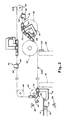
- at least one corner, and typically all four corners of the blank are rounded, with the system 10 being designed to automatically wrap the corners of the wrapper 14 around these rounded corners of the blank 16 in a neatly folded pattern.
- a radiation source 36 and detector 38 are positioned to detect the leading edge 20 of the laminate 12 when the latter arrives at position A.
- the source and detector are preferably positioned respectively below and above one another between the two conveyer belts of conveyor 30 on opposite sides of the plane of the path of the laminate 12, as shown, so that the leading edge 20 of laminate 12 intersects a beam directed from the source 36 toward the detector 38, as the laminate 12 moves into position A.
- both source and detector can be positioned above the belt each directed along a line intersecting at a point at or near the plane of the belt through which point the laminate 12 travels.
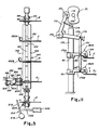
- control system 34 drives the locating mechanism 50, generally shown in Fig. 1 and in greater detail in Fig. 2, which in turn pulls laminate 12 from position A, as it moves off the conveyor 30, and moves the laminate towards and holds it in position B in the wrapping station 18.
- Chains 52 are preferably driven in parallel by control system 34 (shown generally in Fig. 12). As will be more evident from a description of Fig. 12, control system 34 is suitably coupled, for example, to shaft 58 (see Fig. 1). Shaft 58 drives a pair of gears 64, one for driving each of the chains 52 (see Figs. 1 and 2). As shown in Fig. 2, chain 52 is also driven around gears 56, 60, 62 and 66, with the chain passing under gear 60, and around and over gear 62 (so as to pass therebetween) for reasons which will be more apparent hereinafter. Each chain 52 includes one or more pairs of grip ping arms 68 and 70 for pulling each laminate 12 from position A to position B (in Fig. 1). Each of the gripping arms is secured to a link 72 of the chain 52 in such a way that the arms will not interfere with the links of the chain engaging the teeth of the gears 56, 60, 62, 64 and 66.
- the arms 179A and 179B will alternatively pivot clockwise and counterclockwise about the respective pins 181 so as to (a) rotate the wheel assemblies 182A and 182B up and clear of the laminate as the latter moves from its previous position, (b) move the respective wheel 184 against and over the edge of the laminate catching a portion of the wrapper extending beyond the edge of the blank of the laminate as the laminate moves by and (c) move the respective wheel over a portion of the laminate as the latter arrives in the positions C and D.
- the individual roller elements 199 are preferably conne cted to one another so that adjacent elements are capable of pivoting, at least through a limited angle, about the point of the intersection of the rotation axes of each pair of adjacent elements so joined, so as to accommodate any variations in thickness of the laminate as the rollers 196 and 198 engage the edge of the laminate.
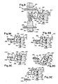
- Means preferably in the form of pressure rollers 252 and 254 (see Figs. 1 and 13E), are provided for pressing the edges down on the blank to insure that the edges are secure.
- the laminate then exits the system as a complete wrapped product, with the corners neatly and automatically wrapped while substantially preserving the roundness of the corner of the blank in the finished product.
- the control system 34 includes suitable drive means, such as a drive motor 260.
- the drive motor 260 is coupled to suitable gearing 262, which in turn supplies the appropriate mechanical torque to pressure rolls 252 and 254, to side wrapping belts 244 and conveyor 30.
- Gearing 262 is also coupled to clutch 264, the latter being coupled to suitable gearing 266.
- Gearing 266 is coupled to camming mechanism 268 which operates roller assembly 190.
- Gearing 266 is also coupled to cam 171 through the shaft 106 for operating the wheel assemblies 182.
- Gearing 266 also drives the carrier chain drive 92.
Landscapes
- Engineering & Computer Science (AREA)
- Mechanical Engineering (AREA)
- Basic Packing Technique (AREA)
- Folding Of Thin Sheet-Like Materials, Special Discharging Devices, And Others (AREA)
- Making Paper Articles (AREA)
Applications Claiming Priority (2)
| Application Number | Priority Date | Filing Date | Title |
|---|---|---|---|
| US923679 | 1986-10-27 | ||
| US06/923,679 US4701238A (en) | 1986-10-27 | 1986-10-27 | Wrapping machine |
Publications (1)
| Publication Number | Publication Date |
|---|---|
| EP0266027A1 true EP0266027A1 (de) | 1988-05-04 |
Family
ID=25449093
Family Applications (1)
| Application Number | Title | Priority Date | Filing Date |
|---|---|---|---|
| EP87306914A Withdrawn EP0266027A1 (de) | 1986-10-27 | 1987-08-05 | Maschine zum Umschlagen vorstehender Ränder |
Country Status (4)
| Country | Link |
|---|---|
| US (1) | US4701238A (de) |
| EP (1) | EP0266027A1 (de) |
| JP (1) | JPS63110117A (de) |
| KR (1) | KR880004946A (de) |
Families Citing this family (9)
| Publication number | Priority date | Publication date | Assignee | Title |
|---|---|---|---|---|
| JPH0730485Y2 (ja) * | 1989-08-17 | 1995-07-12 | 東洋精機株式会社 | 平判包装装置における包装紙敷込み機構 |
| IT1241719B (it) * | 1990-06-01 | 1994-02-01 | Angelis Luciano De | Macchina per ripiegare ed incollare lembi di carta di rivestimento su cartone od altro |
| JPH0730487Y2 (ja) * | 1990-06-15 | 1995-07-12 | 東洋精機株式会社 | 平判包装装置の包装紙敷込み機構 |
| US5393366A (en) * | 1992-12-07 | 1995-02-28 | Profold, Inc. | Aligning and tabbing method and apparatus |
| US6196392B1 (en) | 1997-12-23 | 2001-03-06 | Profold, Inc. | Method and apparatus for feeding and tabbing intermixed pieces of mail |
| US6253820B1 (en) | 1999-06-28 | 2001-07-03 | Inline Plastics Corporation | Label applying apparatus and method therefor |
| US6609662B2 (en) | 2000-02-01 | 2003-08-26 | Profold, Inc. | Debit card having secure scratch-off label strip with releasable layer and method of applying same |
| US6199757B1 (en) | 2000-02-01 | 2001-03-13 | Profold, Inc. | Debit card having scratch-off label strip and method of applying same |
| US6578874B1 (en) | 2000-03-13 | 2003-06-17 | Profold, Inc. | Method for correcting articles of mail and article of mail produced thereby |
Citations (1)
| Publication number | Priority date | Publication date | Assignee | Title |
|---|---|---|---|---|
| US4614512A (en) * | 1982-02-04 | 1986-09-30 | S. A. Martin | Sheet folding machine |
Family Cites Families (4)
| Publication number | Priority date | Publication date | Assignee | Title |
|---|---|---|---|---|
| US720081A (en) * | 1902-09-15 | 1903-02-10 | Smyth Mfg Co | Cloth-folding mechanism. |
| US1776426A (en) * | 1923-08-09 | 1930-09-23 | United Shoe Machinery Corp | Method of and machine for folding sheet material |
| US1833702A (en) * | 1928-02-29 | 1931-11-24 | Joseph W Anthony | Device for forming round corners on book covers |
| US4111739A (en) * | 1974-11-12 | 1978-09-05 | Fmc Corporation | Corner tucking device for laminated sheets |
-
1986
- 1986-10-27 US US06/923,679 patent/US4701238A/en not_active Expired - Fee Related
-
1987
- 1987-07-17 JP JP62177354A patent/JPS63110117A/ja active Pending
- 1987-08-05 EP EP87306914A patent/EP0266027A1/de not_active Withdrawn
- 1987-09-23 KR KR870010548A patent/KR880004946A/ko not_active Withdrawn
Patent Citations (1)
| Publication number | Priority date | Publication date | Assignee | Title |
|---|---|---|---|---|
| US4614512A (en) * | 1982-02-04 | 1986-09-30 | S. A. Martin | Sheet folding machine |
Also Published As
| Publication number | Publication date |
|---|---|
| JPS63110117A (ja) | 1988-05-14 |
| US4701238A (en) | 1987-10-20 |
| KR880004946A (ko) | 1988-06-27 |
Similar Documents
| Publication | Publication Date | Title |
|---|---|---|
| US7069708B2 (en) | Sheet package producing system, sheet handling device, and fillet folding device | |
| US4701238A (en) | Wrapping machine | |
| JPS624169A (ja) | シ−ト材の積重ね兼移送装置 | |
| JPS6238258B2 (de) | ||
| EP0312371A2 (de) | Verfahren und Maschine für das Fertigstellen von Pappschachteln | |
| EP0574557A1 (de) | Apparat zum hochgeschwindigkeit-spateln von papierbögen durch sowohl zickzackfaltung einer fortlaufenden bahn als auch aufeinanderstapeln einzelner bögen | |
| JP2564818Y2 (ja) | 自動包装機の耳折り装置 | |
| CN115285481A (zh) | 一种智能贴标装备 | |
| CN214268279U (zh) | 一种智能贴标装备 | |
| US5184384A (en) | Folding machine | |
| JP3776219B2 (ja) | 用紙のナイフ折り装置 | |
| CA1263416A (en) | High-speed wrapping machine | |
| US20080209856A1 (en) | Work Piece Wrapping Apparatus | |
| JPH0443447Y2 (de) | ||
| JP2676172B2 (ja) | 自動縫製装置 | |
| JPS5920530B2 (ja) | 靴下類の折畳装置 | |
| JPS633922Y2 (de) | ||
| JP3726298B2 (ja) | ストレッチフィルム包装機 | |
| JPH06127513A (ja) | 包装機 | |
| JP2694096B2 (ja) | 包装装置 | |
| JP2629066B2 (ja) | 包装装置 | |
| JPH0232916A (ja) | 包装装置 | |
| GB2159488A (en) | Apparatus for the automatic positioning of tissue and/or card over a shirt to be folded | |
| JP2695334B2 (ja) | 包装装置 | |
| JPS6315122Y2 (de) |
Legal Events
| Date | Code | Title | Description |
|---|---|---|---|
| PUAI | Public reference made under article 153(3) epc to a published international application that has entered the european phase |
Free format text: ORIGINAL CODE: 0009012 |
|
| AK | Designated contracting states |
Kind code of ref document: A1 Designated state(s): DE FR GB IT |
|
| 17P | Request for examination filed |
Effective date: 19881025 |
|
| 17Q | First examination report despatched |
Effective date: 19900712 |
|
| STAA | Information on the status of an ep patent application or granted ep patent |
Free format text: STATUS: THE APPLICATION IS DEEMED TO BE WITHDRAWN |
|
| 18D | Application deemed to be withdrawn |
Effective date: 19910228 |
|
| RIN1 | Information on inventor provided before grant (corrected) |
Inventor name: BOUCHER, RONALD H. |