EP0268741B1 - Détecteur d'ondes optiques cohérentes insensible à la polarisation - Google Patents
Détecteur d'ondes optiques cohérentes insensible à la polarisation Download PDFInfo
- Publication number
- EP0268741B1 EP0268741B1 EP87110516A EP87110516A EP0268741B1 EP 0268741 B1 EP0268741 B1 EP 0268741B1 EP 87110516 A EP87110516 A EP 87110516A EP 87110516 A EP87110516 A EP 87110516A EP 0268741 B1 EP0268741 B1 EP 0268741B1
- Authority
- EP
- European Patent Office
- Prior art keywords
- signal
- lightwave
- photocurrent
- demodulator
- responsive
- Prior art date
- Legal status (The legal status is an assumption and is not a legal conclusion. Google has not performed a legal analysis and makes no representation as to the accuracy of the status listed.)
- Expired - Lifetime
Links
- 230000010287 polarization Effects 0.000 title claims description 34
- 230000001427 coherent effect Effects 0.000 title claims description 15
- 230000003287 optical effect Effects 0.000 claims description 11
- 230000003111 delayed effect Effects 0.000 claims description 6
- 230000008878 coupling Effects 0.000 claims 4
- 238000010168 coupling process Methods 0.000 claims 4
- 238000005859 coupling reaction Methods 0.000 claims 4
- 238000001514 detection method Methods 0.000 description 9
- 238000000034 method Methods 0.000 description 2
- 230000010363 phase shift Effects 0.000 description 2
- 238000011084 recovery Methods 0.000 description 2
- 238000004891 communication Methods 0.000 description 1
- 230000001419 dependent effect Effects 0.000 description 1
Images
Classifications
-
- G—PHYSICS
- G01—MEASURING; TESTING
- G01J—MEASUREMENT OF INTENSITY, VELOCITY, SPECTRAL CONTENT, POLARISATION, PHASE OR PULSE CHARACTERISTICS OF INFRARED, VISIBLE OR ULTRAVIOLET LIGHT; COLORIMETRY; RADIATION PYROMETRY
- G01J4/00—Measuring polarisation of light
- G01J4/04—Polarimeters using electric detection means
-
- H—ELECTRICITY
- H04—ELECTRIC COMMUNICATION TECHNIQUE
- H04B—TRANSMISSION
- H04B10/00—Transmission systems employing electromagnetic waves other than radio-waves, e.g. infrared, visible or ultraviolet light, or employing corpuscular radiation, e.g. quantum communication
- H04B10/60—Receivers
- H04B10/61—Coherent receivers
-
- H—ELECTRICITY
- H04—ELECTRIC COMMUNICATION TECHNIQUE
- H04B—TRANSMISSION
- H04B10/00—Transmission systems employing electromagnetic waves other than radio-waves, e.g. infrared, visible or ultraviolet light, or employing corpuscular radiation, e.g. quantum communication
-
- H—ELECTRICITY
- H04—ELECTRIC COMMUNICATION TECHNIQUE
- H04B—TRANSMISSION
- H04B10/00—Transmission systems employing electromagnetic waves other than radio-waves, e.g. infrared, visible or ultraviolet light, or employing corpuscular radiation, e.g. quantum communication
- H04B10/60—Receivers
- H04B10/61—Coherent receivers
- H04B10/614—Coherent receivers comprising one or more polarization beam splitters, e.g. polarization multiplexed [PolMux] X-PSK coherent receivers, polarization diversity heterodyne coherent receivers
-
- H—ELECTRICITY
- H04—ELECTRIC COMMUNICATION TECHNIQUE
- H04B—TRANSMISSION
- H04B10/00—Transmission systems employing electromagnetic waves other than radio-waves, e.g. infrared, visible or ultraviolet light, or employing corpuscular radiation, e.g. quantum communication
- H04B10/60—Receivers
- H04B10/61—Coherent receivers
- H04B10/615—Arrangements affecting the optical part of the receiver
- H04B10/6151—Arrangements affecting the optical part of the receiver comprising a polarization controller at the receiver's input stage
-
- H—ELECTRICITY
- H04—ELECTRIC COMMUNICATION TECHNIQUE
- H04B—TRANSMISSION
- H04B10/00—Transmission systems employing electromagnetic waves other than radio-waves, e.g. infrared, visible or ultraviolet light, or employing corpuscular radiation, e.g. quantum communication
- H04B10/60—Receivers
- H04B10/61—Coherent receivers
- H04B10/65—Intradyne, i.e. coherent receivers with a free running local oscillator having a frequency close but not phase-locked to the carrier signal
Definitions
- the present invention relates to a polarization insensitive coherent lightwave detector and, more particularly, to a coherent lightwave detection system where only the polarization state of the local oscillator must be known to recover information from the transmitted optical signal.
- the polarization state of the transmitted signal is irrelevant to achieving recovery.
- Coherent lightwave detection systems are becoming increasingly prevalent in many lightwave communication arrangements.
- conventional heterodyne/homodyne techniques are used to recover the transmitted signal.
- These techniques require that the polarization state of the local oscillator be accurately aligned to the polarization state of the message signal to assure accurate recovery of the message.
- This limitation is considered to be a serious drawback to the advance of coherent lightwave detectors.
- One prior art arrangement which addresses this polarization problem is described in the article entitled "Demodulation of Optical DPSK Using In-Phase and Quadrature Detection" by T. G. Hodgkinson et al appearing in Electronic Letters, Vol. 21, No. 19, September 1985, at pp.
- a 90 optical hybrid is used to achieve the in-phase and quadrature detection, where the local oscillator is connected to a first input of the hybrid via a first polarization controlling member and the transmitted DPSK signal is connected to the remaining input of the hybrid via a second polarization controlling member.
- the polarization controllers must be monitored to insure correct operation of the demodulator.
- the present invention relates to a polarization insensitive coherent lightwave detection system which performs a squaring operation in order to remove the message signal's polarization state from the final recovered data signal.
- Delay demodulators may be used to perform this squaring operation.
- the present invention may utilize a balanced design including a pair of optical hybrids and a pair of balanced detectors to maintain the advantages of prior art balanced arrangements, including common-mode rejection and maximization of optical signal power.
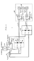
- the sole Figure illustrates a double balanced DPSK coherent detection system according to the present invention which is insensitive to the polarization state of the DPSK message signal.
- received message signal E R and local oscillator signal E L are first applied as separate inputs to a 3dB optical coupler 10.
- Received signal E R is presumed to be a DPSK signal for the purposes of the present discussion, and can be expressed as where M(t) represents the DPSK modulation signal, ⁇ R is the carrier frequency and ⁇ R(t) is the phase noise associated with the carrier.
- local oscillator signal E L can be expressed as where ⁇ L is the carrier frequency and ⁇ L(t) is the phase noise associated with the carrier.
- Output signals E 1 (t) and E 2 (t) subsequently travel along a separate pair of signal paths, where E 1 (t) is applied as an input to a first 90° hybrid component 12 and E 2 (t) is applied as an input to a second 90° hybrid component 14.
- Hybrids 12 and 14 can also be considered as polarization-selective beam splitters which will split the input signal into "horizontal” and “vertical” components. Therefore, in accordance with equations (3)-(6), the four outputs from hybrids 12 and 14 will be: where 6 is defined as the phase shift introduced by hybrid components 12 and 14.
- balanced receiver 16 comprises a pair of photodiodes 18 and 20, each photodiode responsive to a separate one of the signals E 1V (t) and E 2 v(t).
- photodiode 18 is responsive to signal E iv (t)
- photodiode 20 is responsive to signal E 2v (t).
- the lightwave signal is transformed into a current, where the pair of currents are applied as an input to an amplifying component 22.
- output photocurrent i v (t) from balanced receiver 16 is applied to a first delay component 32 of demodulator 30, where component 32 forms a version of i v (t) which is delayed by a predetermined time interval T and multiplies i v (t) by i v (t-T), where this multiplicative product is denoted D v (t).
- output photocurrent i h (t) is applied to a second delay component 34 to form a second delayed signal D h (t), where D h (t) can be expressed as
- D h (t) can be expressed as
- the final recovered data signal D(t) can therefore be obtained by adding together the components D v (t) and D h (t), as illustrated by the summing unit 36.
- D(t) can be expressed as which in accordance with the teachings of the present invention is independent of the polarization parameter ⁇ of received message signal E R (t).
Landscapes
- Physics & Mathematics (AREA)
- Electromagnetism (AREA)
- Engineering & Computer Science (AREA)
- Computer Networks & Wireless Communication (AREA)
- Signal Processing (AREA)
- General Physics & Mathematics (AREA)
- Spectroscopy & Molecular Physics (AREA)
- Optical Communication System (AREA)
Claims (5)
Applications Claiming Priority (2)
| Application Number | Priority Date | Filing Date | Title |
|---|---|---|---|
| US06/933,827 US4718120A (en) | 1986-11-24 | 1986-11-24 | Polarization insensitive coherent lightwave detector |
| US933827 | 1986-11-24 |
Publications (3)
| Publication Number | Publication Date |
|---|---|
| EP0268741A2 EP0268741A2 (fr) | 1988-06-01 |
| EP0268741A3 EP0268741A3 (en) | 1989-08-16 |
| EP0268741B1 true EP0268741B1 (fr) | 1992-10-28 |
Family
ID=25464569
Family Applications (1)
| Application Number | Title | Priority Date | Filing Date |
|---|---|---|---|
| EP87110516A Expired - Lifetime EP0268741B1 (fr) | 1986-11-24 | 1987-07-21 | Détecteur d'ondes optiques cohérentes insensible à la polarisation |
Country Status (7)
| Country | Link |
|---|---|
| US (1) | US4718120A (fr) |
| EP (1) | EP0268741B1 (fr) |
| JP (1) | JP2723229B2 (fr) |
| KR (1) | KR910003237B1 (fr) |
| CA (1) | CA1253571A (fr) |
| DE (1) | DE3782402T2 (fr) |
| ES (1) | ES2036195T3 (fr) |
Families Citing this family (36)
| Publication number | Priority date | Publication date | Assignee | Title |
|---|---|---|---|---|
| CA1290019C (fr) * | 1986-06-20 | 1991-10-01 | Hideo Kuwahara | Recepteur de signaux lumineux a dedoublement |
| DE3621734A1 (de) * | 1986-06-28 | 1988-01-07 | Standard Elektrik Lorenz Ag | Optischer ueberlagerungsempfaenger |
| GB8625416D0 (en) * | 1986-10-23 | 1987-02-04 | Plessey Co Plc | Optical fsk demodulator |
| US4829598A (en) * | 1987-01-22 | 1989-05-09 | Siemens Aktiengesellschaft | Optical receiver with an optical coupler and an electronic amplifier |
| CA1308440C (fr) * | 1987-03-13 | 1992-10-06 | Hideaki Tsushima | Methode de communication optique a diversite de polarisation et appareil utilisant cette methode |
| JP2562623B2 (ja) * | 1987-10-28 | 1996-12-11 | 国際電信電話株式会社 | ベースバンド合成法による偏波ダイバーシティ光受信方式 |
| JP2642173B2 (ja) * | 1988-12-13 | 1997-08-20 | 日本電信電話株式会社 | 光ヘテロダイン検波回路 |
| JP2642174B2 (ja) * | 1988-12-13 | 1997-08-20 | 日本電信電話株式会社 | 光ヘテロダイン検波回路 |
| JPH02162330A (ja) * | 1988-12-16 | 1990-06-21 | Hitachi Ltd | 偏波ダイバシティ光受信方法とその装置および中間周波数安定化方法 |
| US4998295A (en) * | 1988-12-30 | 1991-03-05 | General Electric Company | Receiver having an interferometer |
| US4962762A (en) * | 1989-02-21 | 1990-10-16 | Beekil Steven L | Modular self-contained orthotic device |
| EP0401557A3 (fr) * | 1989-06-06 | 1991-10-02 | Siemens Aktiengesellschaft | Procédé pour réaliser une réception hétérodyne optique insensible à la phase et/ou à la polarisation d'un signal modulé en sauts de fréquence |
| US5115332A (en) * | 1989-07-20 | 1992-05-19 | Fujitsu Limited | Receiver for coherent optical communication |
| US5048120A (en) * | 1989-08-28 | 1991-09-10 | Siemens Aktiengesellschaft | Arrangement for the generation of an FSK-modulated optical signal having two polarization states that are orthogonal to one another from an FSK-modulated optical transmitted signal |
| US5200795A (en) * | 1989-08-31 | 1993-04-06 | The Board Of Trustees Of The Leland Stanford Junior University | Passive quadrature phase detection system for coherent fiber optic systems |
| US5060312A (en) * | 1990-03-05 | 1991-10-22 | At&T Bell Laboratories | Polarization independent coherent lightwave detection arrangement |
| US5027436A (en) * | 1990-04-27 | 1991-06-25 | At&T Bell Laboratories | Optical hybrid for coherent detection systems |
| GB2245117B (en) * | 1990-06-14 | 1994-04-06 | Stc Plc | Optical mixing for heterodyne detection |
| JP3001943B2 (ja) * | 1990-08-30 | 2000-01-24 | 株式会社東芝 | 偏波スイッチング光源、光受信装置及びコヒーレント光伝送システム |
| JPH04144320A (ja) * | 1990-10-05 | 1992-05-18 | Hitachi Ltd | ホモダイン光受信装置 |
| US5307197A (en) * | 1991-08-27 | 1994-04-26 | Nec Corporation | Optical circuit for a polarization diversity receiver |
| US5654818A (en) * | 1996-02-09 | 1997-08-05 | The United States Of America As Represented By The United States National Aeronautics And Space Administration | Polarization independent electro-optic modulator |
| US6782211B1 (en) * | 1998-11-05 | 2004-08-24 | Mark T. Core | Cross polarization interface canceler |
| US7110677B2 (en) * | 2001-09-26 | 2006-09-19 | Celight, Inc. | Method and system for optical time division multiplexed fiber communications with coherent detection |
| US6856400B1 (en) | 2000-12-14 | 2005-02-15 | Luna Technologies | Apparatus and method for the complete characterization of optical devices including loss, birefringence and dispersion effects |
| US6407848B1 (en) | 2000-12-27 | 2002-06-18 | All Optical Networks, Inc. | Servo-stabilized-phase, differential coherence detector |
| US6473222B2 (en) | 2000-12-27 | 2002-10-29 | John N. Hait | Hyper-heterodyning, expanded bandpass apparatus and method |
| US7529481B1 (en) * | 2003-03-13 | 2009-05-05 | State Of Oregon Acting By And Through The State Board Of Higher Education On Behalf Of The University Of Oregon | Linear optical sampling methods and apparatus |
| JP4170298B2 (ja) * | 2005-01-31 | 2008-10-22 | 富士通株式会社 | 差分4位相偏移変調方式に対応した光受信器および光受信方法 |
| US7809284B2 (en) * | 2006-06-23 | 2010-10-05 | Alcatel-Lucent Usa Inc. | System and method for receiving coherent, polarization-multiplexed optical signals |
| US8437645B2 (en) * | 2007-12-06 | 2013-05-07 | Google Inc. | System and method for coherent detection of optical signals |
| US8204378B1 (en) | 2008-03-27 | 2012-06-19 | Tektronix, Inc. | Coherent optical signal processing |
| US20100054761A1 (en) * | 2008-08-28 | 2010-03-04 | Young-Kai Chen | Monolithic coherent optical detectors |
| EP2326978A2 (fr) * | 2008-08-19 | 2011-06-01 | Alcatel-Lucent USA Inc. | Détecteurs optiques cohérents monolithiques |
| US20100158521A1 (en) * | 2008-12-18 | 2010-06-24 | Alcatel-Lucent Usa Inc. | Optical mixer for coherent detection of polarization-multiplexed signals |
| WO2010107439A1 (fr) | 2009-03-20 | 2010-09-23 | Alcatel-Lucent Usa Inc. | Capteur optique cohérent comportant un réseau de guides d'onde à fonctions multiples |
Family Cites Families (4)
| Publication number | Priority date | Publication date | Assignee | Title |
|---|---|---|---|---|
| US3214590A (en) * | 1962-06-28 | 1965-10-26 | Bell Telephone Labor Inc | Communication receiver utilizing negative feedback polarization modulation of electromagnetic waves and communication system including said receiver |
| US3971930A (en) * | 1974-04-24 | 1976-07-27 | The United States Of America As Represented By The Administrator Of The National Aeronautics And Space Administration | Polarization compensator for optical communications |
| FR2517081A1 (fr) * | 1981-11-26 | 1983-05-27 | Monerie Michel | Procede de detection coherente et de demodulation d'une onde porteuse modulee a etat de polarisation variable et dispositif de mise en oeuvre |
| JPS6325623A (ja) * | 1986-07-17 | 1988-02-03 | Canon Inc | 液晶表示装置の製造方法 |
-
1986
- 1986-11-24 US US06/933,827 patent/US4718120A/en not_active Expired - Lifetime
-
1987
- 1987-06-30 CA CA000540964A patent/CA1253571A/fr not_active Expired
- 1987-07-21 DE DE8787110516T patent/DE3782402T2/de not_active Expired - Fee Related
- 1987-07-21 EP EP87110516A patent/EP0268741B1/fr not_active Expired - Lifetime
- 1987-07-21 ES ES198787110516T patent/ES2036195T3/es not_active Expired - Lifetime
- 1987-07-23 KR KR1019870008002A patent/KR910003237B1/ko not_active Expired
- 1987-07-24 JP JP62183786A patent/JP2723229B2/ja not_active Expired - Lifetime
Also Published As
| Publication number | Publication date |
|---|---|
| EP0268741A2 (fr) | 1988-06-01 |
| DE3782402T2 (de) | 1993-05-27 |
| EP0268741A3 (en) | 1989-08-16 |
| KR880006532A (ko) | 1988-07-23 |
| KR910003237B1 (ko) | 1991-05-24 |
| CA1253571A (fr) | 1989-05-02 |
| DE3782402D1 (de) | 1992-12-03 |
| JP2723229B2 (ja) | 1998-03-09 |
| US4718120A (en) | 1988-01-05 |
| JPS63143531A (ja) | 1988-06-15 |
| ES2036195T3 (es) | 1993-05-16 |
Similar Documents
| Publication | Publication Date | Title |
|---|---|---|
| EP0268741B1 (fr) | Détecteur d'ondes optiques cohérentes insensible à la polarisation | |
| EP0445943B1 (fr) | Dispositif de détection d'ondes optiques cohérentes indépendant de la polarisation | |
| Davis et al. | Phase diversity techniques for coherent optical receivers | |
| EP0198239B1 (fr) | Récepteur optique | |
| US9755759B2 (en) | Polarisation-independent coherent optical receiver | |
| US5027436A (en) | Optical hybrid for coherent detection systems | |
| JPS6325632A (ja) | 光ヘテロダイン受信機 | |
| US7085501B1 (en) | Coherent optical receiver | |
| EP0245026B1 (fr) | Mélangeur optique hétérodyne procurant une réjection des fréquences-images | |
| EP0265278B1 (fr) | Démodulateur pour modulation à déplacement de fréquence optique | |
| US5510927A (en) | Method for setting the local oscillator of an optical superheterodyne receiver | |
| CA1308440C (fr) | Methode de communication optique a diversite de polarisation et appareil utilisant cette methode | |
| CN117176259A (zh) | 一种基于自相干的四路复用光通信方法及装置 | |
| US6704375B1 (en) | Device for the homodyne reception of optically phase-keyed signals | |
| US20240121006A1 (en) | Coherent detection method and apparatus, and optical transmission system | |
| JPH0285830A (ja) | コヒーレント光受信方式 | |
| JPH05224267A (ja) | 光受信器 | |
| JPS61267422A (ja) | 光ヘテロダイン検波通信方法 | |
| JPH0239741A (ja) | 偏波ダイバーシチ型光ヘテロダイン受信装置 | |
| JPH0267831A (ja) | 光受信装置 |
Legal Events
| Date | Code | Title | Description |
|---|---|---|---|
| PUAI | Public reference made under article 153(3) epc to a published international application that has entered the european phase |
Free format text: ORIGINAL CODE: 0009012 |
|
| AK | Designated contracting states |
Kind code of ref document: A2 Designated state(s): DE ES FR GB NL SE |
|
| PUAL | Search report despatched |
Free format text: ORIGINAL CODE: 0009013 |
|
| AK | Designated contracting states |
Kind code of ref document: A3 Designated state(s): DE ES FR GB NL SE |
|
| 17P | Request for examination filed |
Effective date: 19900209 |
|
| 17Q | First examination report despatched |
Effective date: 19920410 |
|
| GRAA | (expected) grant |
Free format text: ORIGINAL CODE: 0009210 |
|
| AK | Designated contracting states |
Kind code of ref document: B1 Designated state(s): DE ES FR GB NL SE |
|
| REF | Corresponds to: |
Ref document number: 3782402 Country of ref document: DE Date of ref document: 19921203 |
|
| ET | Fr: translation filed | ||
| REG | Reference to a national code |
Ref country code: ES Ref legal event code: FG2A Ref document number: 2036195 Country of ref document: ES Kind code of ref document: T3 |
|
| PLBE | No opposition filed within time limit |
Free format text: ORIGINAL CODE: 0009261 |
|
| STAA | Information on the status of an ep patent application or granted ep patent |
Free format text: STATUS: NO OPPOSITION FILED WITHIN TIME LIMIT |
|
| 26N | No opposition filed | ||
| EAL | Se: european patent in force in sweden |
Ref document number: 87110516.9 |
|
| PGFP | Annual fee paid to national office [announced via postgrant information from national office to epo] |
Ref country code: SE Payment date: 20000620 Year of fee payment: 14 |
|
| PGFP | Annual fee paid to national office [announced via postgrant information from national office to epo] |
Ref country code: FR Payment date: 20010625 Year of fee payment: 15 |
|
| PGFP | Annual fee paid to national office [announced via postgrant information from national office to epo] |
Ref country code: GB Payment date: 20010628 Year of fee payment: 15 |
|
| PGFP | Annual fee paid to national office [announced via postgrant information from national office to epo] |
Ref country code: ES Payment date: 20010716 Year of fee payment: 15 |
|
| PGFP | Annual fee paid to national office [announced via postgrant information from national office to epo] |
Ref country code: NL Payment date: 20010717 Year of fee payment: 15 |
|
| PG25 | Lapsed in a contracting state [announced via postgrant information from national office to epo] |
Ref country code: SE Free format text: LAPSE BECAUSE OF NON-PAYMENT OF DUE FEES Effective date: 20010722 |
|
| PGFP | Annual fee paid to national office [announced via postgrant information from national office to epo] |
Ref country code: DE Payment date: 20010928 Year of fee payment: 15 |
|
| REG | Reference to a national code |
Ref country code: GB Ref legal event code: IF02 |
|
| EUG | Se: european patent has lapsed |
Ref document number: 87110516.9 |
|
| PG25 | Lapsed in a contracting state [announced via postgrant information from national office to epo] |
Ref country code: GB Free format text: LAPSE BECAUSE OF NON-PAYMENT OF DUE FEES Effective date: 20020721 |
|
| PG25 | Lapsed in a contracting state [announced via postgrant information from national office to epo] |
Ref country code: ES Free format text: LAPSE BECAUSE OF NON-PAYMENT OF DUE FEES Effective date: 20020722 |
|
| PG25 | Lapsed in a contracting state [announced via postgrant information from national office to epo] |
Ref country code: NL Free format text: LAPSE BECAUSE OF NON-PAYMENT OF DUE FEES Effective date: 20030201 Ref country code: DE Free format text: LAPSE BECAUSE OF NON-PAYMENT OF DUE FEES Effective date: 20030201 |
|
| GBPC | Gb: european patent ceased through non-payment of renewal fee |
Effective date: 20020721 |
|
| PG25 | Lapsed in a contracting state [announced via postgrant information from national office to epo] |
Ref country code: FR Free format text: LAPSE BECAUSE OF NON-PAYMENT OF DUE FEES Effective date: 20030331 |
|
| NLV4 | Nl: lapsed or anulled due to non-payment of the annual fee |
Effective date: 20030201 |
|
| REG | Reference to a national code |
Ref country code: FR Ref legal event code: ST |
|
| REG | Reference to a national code |
Ref country code: ES Ref legal event code: FD2A Effective date: 20030811 |