EP0269548A2 - Système de coupe et de transport pour feuilles - Google Patents
Système de coupe et de transport pour feuilles Download PDFInfo
- Publication number
- EP0269548A2 EP0269548A2 EP87630238A EP87630238A EP0269548A2 EP 0269548 A2 EP0269548 A2 EP 0269548A2 EP 87630238 A EP87630238 A EP 87630238A EP 87630238 A EP87630238 A EP 87630238A EP 0269548 A2 EP0269548 A2 EP 0269548A2
- Authority
- EP
- European Patent Office
- Prior art keywords
- knife
- anvil
- sheet member
- knife anvil
- idler
- Prior art date
- Legal status (The legal status is an assumption and is not a legal conclusion. Google has not performed a legal analysis and makes no representation as to the accuracy of the status listed.)
- Granted
Links
Images


Classifications
-
- B—PERFORMING OPERATIONS; TRANSPORTING
- B29—WORKING OF PLASTICS; WORKING OF SUBSTANCES IN A PLASTIC STATE IN GENERAL
- B29D—PRODUCING PARTICULAR ARTICLES FROM PLASTICS OR FROM SUBSTANCES IN A PLASTIC STATE
- B29D30/00—Producing pneumatic or solid tyres or parts thereof
- B29D30/06—Pneumatic tyres or parts thereof (e.g. produced by casting, moulding, compression moulding, injection moulding, centrifugal casting)
- B29D30/38—Textile inserts, e.g. cord or canvas layers, for tyres; Treatment of inserts prior to building the tyre
- B29D30/46—Cutting textile inserts to required shape
-
- B—PERFORMING OPERATIONS; TRANSPORTING
- B26—HAND CUTTING TOOLS; CUTTING; SEVERING
- B26D—CUTTING; DETAILS COMMON TO MACHINES FOR PERFORATING, PUNCHING, CUTTING-OUT, STAMPING-OUT OR SEVERING
- B26D1/00—Cutting through work characterised by the nature or movement of the cutting member or particular materials not otherwise provided for; Apparatus or machines therefor; Cutting members therefor
- B26D1/01—Cutting through work characterised by the nature or movement of the cutting member or particular materials not otherwise provided for; Apparatus or machines therefor; Cutting members therefor involving a cutting member which does not travel with the work
- B26D1/12—Cutting through work characterised by the nature or movement of the cutting member or particular materials not otherwise provided for; Apparatus or machines therefor; Cutting members therefor involving a cutting member which does not travel with the work having a cutting member moving about an axis
- B26D1/14—Cutting through work characterised by the nature or movement of the cutting member or particular materials not otherwise provided for; Apparatus or machines therefor; Cutting members therefor involving a cutting member which does not travel with the work having a cutting member moving about an axis with a circular cutting member, e.g. disc cutter
- B26D1/20—Cutting through work characterised by the nature or movement of the cutting member or particular materials not otherwise provided for; Apparatus or machines therefor; Cutting members therefor involving a cutting member which does not travel with the work having a cutting member moving about an axis with a circular cutting member, e.g. disc cutter coacting with a fixed member
-
- B—PERFORMING OPERATIONS; TRANSPORTING
- B26—HAND CUTTING TOOLS; CUTTING; SEVERING
- B26D—CUTTING; DETAILS COMMON TO MACHINES FOR PERFORATING, PUNCHING, CUTTING-OUT, STAMPING-OUT OR SEVERING
- B26D1/00—Cutting through work characterised by the nature or movement of the cutting member or particular materials not otherwise provided for; Apparatus or machines therefor; Cutting members therefor
- B26D1/01—Cutting through work characterised by the nature or movement of the cutting member or particular materials not otherwise provided for; Apparatus or machines therefor; Cutting members therefor involving a cutting member which does not travel with the work
- B26D1/12—Cutting through work characterised by the nature or movement of the cutting member or particular materials not otherwise provided for; Apparatus or machines therefor; Cutting members therefor involving a cutting member which does not travel with the work having a cutting member moving about an axis
- B26D1/14—Cutting through work characterised by the nature or movement of the cutting member or particular materials not otherwise provided for; Apparatus or machines therefor; Cutting members therefor involving a cutting member which does not travel with the work having a cutting member moving about an axis with a circular cutting member, e.g. disc cutter
- B26D1/20—Cutting through work characterised by the nature or movement of the cutting member or particular materials not otherwise provided for; Apparatus or machines therefor; Cutting members therefor involving a cutting member which does not travel with the work having a cutting member moving about an axis with a circular cutting member, e.g. disc cutter coacting with a fixed member
- B26D1/205—Cutting through work characterised by the nature or movement of the cutting member or particular materials not otherwise provided for; Apparatus or machines therefor; Cutting members therefor involving a cutting member which does not travel with the work having a cutting member moving about an axis with a circular cutting member, e.g. disc cutter coacting with a fixed member for thin material, e.g. for sheets, strips or the like
-
- Y—GENERAL TAGGING OF NEW TECHNOLOGICAL DEVELOPMENTS; GENERAL TAGGING OF CROSS-SECTIONAL TECHNOLOGIES SPANNING OVER SEVERAL SECTIONS OF THE IPC; TECHNICAL SUBJECTS COVERED BY FORMER USPC CROSS-REFERENCE ART COLLECTIONS [XRACs] AND DIGESTS
- Y10—TECHNICAL SUBJECTS COVERED BY FORMER USPC
- Y10T—TECHNICAL SUBJECTS COVERED BY FORMER US CLASSIFICATION
- Y10T156/00—Adhesive bonding and miscellaneous chemical manufacture
- Y10T156/12—Surface bonding means and/or assembly means with cutting, punching, piercing, severing or tearing
- Y10T156/1317—Means feeding plural workpieces to be joined
- Y10T156/1322—Severing before bonding or assembling of parts
-
- Y—GENERAL TAGGING OF NEW TECHNOLOGICAL DEVELOPMENTS; GENERAL TAGGING OF CROSS-SECTIONAL TECHNOLOGIES SPANNING OVER SEVERAL SECTIONS OF THE IPC; TECHNICAL SUBJECTS COVERED BY FORMER USPC CROSS-REFERENCE ART COLLECTIONS [XRACs] AND DIGESTS
- Y10—TECHNICAL SUBJECTS COVERED BY FORMER USPC
- Y10T—TECHNICAL SUBJECTS COVERED BY FORMER US CLASSIFICATION
- Y10T83/00—Cutting
- Y10T83/04—Processes
- Y10T83/0448—With subsequent handling [i.e., of product]
-
- Y—GENERAL TAGGING OF NEW TECHNOLOGICAL DEVELOPMENTS; GENERAL TAGGING OF CROSS-SECTIONAL TECHNOLOGIES SPANNING OVER SEVERAL SECTIONS OF THE IPC; TECHNICAL SUBJECTS COVERED BY FORMER USPC CROSS-REFERENCE ART COLLECTIONS [XRACs] AND DIGESTS
- Y10—TECHNICAL SUBJECTS COVERED BY FORMER USPC
- Y10T—TECHNICAL SUBJECTS COVERED BY FORMER US CLASSIFICATION
- Y10T83/00—Cutting
- Y10T83/04—Processes
- Y10T83/0605—Cut advances across work surface
-
- Y—GENERAL TAGGING OF NEW TECHNOLOGICAL DEVELOPMENTS; GENERAL TAGGING OF CROSS-SECTIONAL TECHNOLOGIES SPANNING OVER SEVERAL SECTIONS OF THE IPC; TECHNICAL SUBJECTS COVERED BY FORMER USPC CROSS-REFERENCE ART COLLECTIONS [XRACs] AND DIGESTS
- Y10—TECHNICAL SUBJECTS COVERED BY FORMER USPC
- Y10T—TECHNICAL SUBJECTS COVERED BY FORMER US CLASSIFICATION
- Y10T83/00—Cutting
- Y10T83/202—With product handling means
- Y10T83/2092—Means to move, guide, or permit free fall or flight of product
- Y10T83/2192—Endless conveyor
-
- Y—GENERAL TAGGING OF NEW TECHNOLOGICAL DEVELOPMENTS; GENERAL TAGGING OF CROSS-SECTIONAL TECHNOLOGIES SPANNING OVER SEVERAL SECTIONS OF THE IPC; TECHNICAL SUBJECTS COVERED BY FORMER USPC CROSS-REFERENCE ART COLLECTIONS [XRACs] AND DIGESTS
- Y10—TECHNICAL SUBJECTS COVERED BY FORMER USPC
- Y10T—TECHNICAL SUBJECTS COVERED BY FORMER US CLASSIFICATION
- Y10T83/00—Cutting
- Y10T83/444—Tool engages work during dwell of intermittent workfeed
- Y10T83/4493—Tool motion initiates work feed and vice versa
-
- Y—GENERAL TAGGING OF NEW TECHNOLOGICAL DEVELOPMENTS; GENERAL TAGGING OF CROSS-SECTIONAL TECHNOLOGIES SPANNING OVER SEVERAL SECTIONS OF THE IPC; TECHNICAL SUBJECTS COVERED BY FORMER USPC CROSS-REFERENCE ART COLLECTIONS [XRACs] AND DIGESTS
- Y10—TECHNICAL SUBJECTS COVERED BY FORMER USPC
- Y10T—TECHNICAL SUBJECTS COVERED BY FORMER US CLASSIFICATION
- Y10T83/00—Cutting
- Y10T83/444—Tool engages work during dwell of intermittent workfeed
- Y10T83/4645—With means to clamp work during dwell
-
- Y—GENERAL TAGGING OF NEW TECHNOLOGICAL DEVELOPMENTS; GENERAL TAGGING OF CROSS-SECTIONAL TECHNOLOGIES SPANNING OVER SEVERAL SECTIONS OF THE IPC; TECHNICAL SUBJECTS COVERED BY FORMER USPC CROSS-REFERENCE ART COLLECTIONS [XRACs] AND DIGESTS
- Y10—TECHNICAL SUBJECTS COVERED BY FORMER USPC
- Y10T—TECHNICAL SUBJECTS COVERED BY FORMER US CLASSIFICATION
- Y10T83/00—Cutting
- Y10T83/748—With work immobilizer
-
- Y—GENERAL TAGGING OF NEW TECHNOLOGICAL DEVELOPMENTS; GENERAL TAGGING OF CROSS-SECTIONAL TECHNOLOGIES SPANNING OVER SEVERAL SECTIONS OF THE IPC; TECHNICAL SUBJECTS COVERED BY FORMER USPC CROSS-REFERENCE ART COLLECTIONS [XRACs] AND DIGESTS
- Y10—TECHNICAL SUBJECTS COVERED BY FORMER USPC
- Y10T—TECHNICAL SUBJECTS COVERED BY FORMER US CLASSIFICATION
- Y10T83/00—Cutting
- Y10T83/768—Rotatable disc tool pair or tool and carrier
- Y10T83/7755—Carrier for rotatable tool movable during cutting
- Y10T83/7763—Tool carrier reciprocable rectilinearly
- Y10T83/7776—With means to reciprocate carrier
-
- Y—GENERAL TAGGING OF NEW TECHNOLOGICAL DEVELOPMENTS; GENERAL TAGGING OF CROSS-SECTIONAL TECHNOLOGIES SPANNING OVER SEVERAL SECTIONS OF THE IPC; TECHNICAL SUBJECTS COVERED BY FORMER USPC CROSS-REFERENCE ART COLLECTIONS [XRACs] AND DIGESTS
- Y10—TECHNICAL SUBJECTS COVERED BY FORMER USPC
- Y10T—TECHNICAL SUBJECTS COVERED BY FORMER US CLASSIFICATION
- Y10T83/00—Cutting
- Y10T83/869—Means to drive or to guide tool
- Y10T83/8821—With simple rectilinear reciprocating motion only
- Y10T83/8822—Edge-to-edge of sheet or web [e.g., traveling cutter]
Definitions
- This invention relates generally to the cutting of sheet members and especially to transporting and cutting tire innerliners to-length prior to application of the innerliners to a tire building drum.
- innerliners were cut by electrically heated knives while the innerliner stock was supported on a takeaway belt conveyor. This procedure required periodic cleaning of the knife and caused deterioration of the belt.
- Other cutting systems have used retractable fingers for extending the stock across the knife anvil. These systems have not been completely satisfactory for innerliner stock which is thin, unreinforced, and requires support to avoid distortion and balling-up.
- the present invention maintains the support for the innerliner stock and avoids stretching forces which could distort the innerliner stock.
- apparatus for cutting a sheet member comprising a supporting structure, a knife anvil extending across the structure, a knife holder mounted on the structure for movement across the structure over the knife anvil, a knife mounted in the knife holder and engageable with the knife anvil for cutting a portion of the sheet member overlying the knife anvil, a feed conveyor assembly having a frame movable between a first position adjacent the knife anvil and a second position overlapping the knife anvil, means for moving the frame from the first position to the second position, means for driving the feed conveyor assembly to transport the sheet member over the knife anvil with the frame in the second position, means for moving the frame from the second position to the first position after the sheet member is transported over the knife anvil, and means for moving the knife holder in a direction across the supporting structure and over the knife anvil to cut the sheet member.
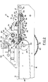
- FIG. 1 and 2 a section of an innerliner cutting and applying assembly 10 is shown in which a sheet member such as innerliner 12 is conveyed over a knife anvil 14 for cutting by a rotary knife 16.
- the innerliner applying and cutting assembly 10 has a main frame 18 with side plates 20 connected by suitable transverse members such as spacer bars 22.
- the main frame 18 supports rollers 24 at the entrance end of the assembly and a takeaway conveyor 26 at the applier end.
- a drive pulley 28, which may be crowned, is rotatably mounted on an applier drive shaft 30 mounted on the main frame 18 and may be driven by a suitable applier drive such as a motor (not shown).
- the takeaway conveyor 26 has a belt 31 extending around the drive pulley 28 at one end of the conveyor and over an exit pulley (not shown) at the applier end for applying the innerliner 12 to a tire building machine drum.
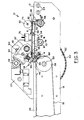
- a feed conveyor assembly such as advance conveyor 32 is located between the rollers 24 and the knife anvil 14 in a first lowered position A as shown in Figs 1 and 2 and in a second raised position B with the advance conveyor overlapping the knife anvil 14 as shown in Fig 3.
- the advance conveyor 32 has a frame 34 with a central plate 36 and side plates 38 connected by transverse frame spacers 40 and a tie bar 42.
- a drive pulley 44 is rotatably mounted on the central plate 36 and side plates 38 at the end of the advance conveyor 32 adjacent the rollers 24.
- a return pulley 46 is rotatably mounted on the central plate 36 and side plates 38 at the forward end 51 of the advance conveyor 32 adjacent the knife anvil 14.
- Separate belts 48 and 50 in side-by-side relation may extend around the drive pulley 44 and return pulley 46, as shown in Fig 1, for conveying the innerliner 12.
- an idler sprocket 58 is mounted on the idler shaft 56 and is driven by a roller chain 60 extending around the idler sprocket and around a drive sprocket 62 mounted on the applier drive shaft 30.
- An advance conveyor clutch 64 may be interposed between the idler sprocket 58 and the idler shaft 56 to control the rotation of the idler shaft.
- An advance conveyor drive sprocket 66 is mounted on the drive pulley 44 and driven by a roller chain 68 extending around an idler shaft sprocket 70.
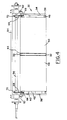
- the idler arms 52 are folded back from the position shown in Fig 4 to a position with the arms underneath the advance conveyor 32 and pivoted about the idler shaft 56.
- the roller chain 60 extending around the drive sprocket 62 and the idler shaft sprocket 70 rotates the shaft and through the roller chain 68 rotates the drive pulley 44.
- a second pair of bar members such as pivot arms 72 with one end of each of the arms pivotally connected to one of the side plates 38 and the other end of each of the pivot arms mounted on a drive shaft 74 of a rotary actuator 76.
- the idler arms 52 and the pivot arms 72 are substantially parallel bars for swinging movement of the frame 34 of the advance conveyor 32 between the first lowered position A and the second raised position B of the advance conveyor.
- a holddown shaft 78 is mounted on brackets 80 fastened to the side plates 38 of the advance conveyor 32 and extends across the conveyor at a position above the belts 48 and 50.
- Holddown rollers 82 may be rotatably mounted on the shaft 78 for engagement with the innerliner 12 as it is fed toward the knife anvil 14.
- the knife anvil 14 has an anvil insert 84 replaceably mounted on the anvil with a cutting edge 86.
- the anvil 14 also has openings 88 in communication with a source of vacuum for holding the innerliner 12 in place during the cutting operation.
- the rotary knife 16 is mounted on a spindle 90 rotatably supported in a knife holder such as rocker spindle housing 92 slidably mounted on a ball bushing shaft 97 and air cylinder 98 extending across the main frame 18 and beyond the side plates 20 so that the housing can move from a position of rest at either side of the advance conveyor 32.
- a knife holder such as rocker spindle housing 92 slidably mounted on a ball bushing shaft 97 and air cylinder 98 extending across the main frame 18 and beyond the side plates 20 so that the housing can move from a position of rest at either side of the advance conveyor 32.
- Suitable means such as a piston a with a magnetic coupling to the housing 92 in the cylinder 98 may be provided to move the housing 92 across the knife anvil 14 with the rotary knife 16 in cutting engagement with the cutting edge 86 of the anvil insert 84.
- the cylinder 98 is in communication with a source of air pressure at each end for moving the piston and housing 92 over the knife anvil 14 in both directions.
- the spindle 90 is mounted for rocking movement of the rotary knife 16 in the housing 92 in an opposite direction from the direction in which the knife is moved over the anvil 14.
- the spindle 90 is supported in a cylindrical rocker 93 for rocking of the rotary knife 16 to the left as indicated by arrow L when the housing 92 is moved to the right as shown in Fig 5.
- the rotary knife 16 is rocked to the right as indicated by arrow R.
- the innerliner 12 is in the position shown in Figs 1 and 2 after the innerliner has been cut by the rotary knife 16 and the cut sections conveyed by the takeaway conveyor 26 to a tire building machine.
- a leading end 99 extends beyond the forward end 51 of the advance conveyor 32 in the cut position as shown in Figs 1 and 2.
- the advance conveyor 32 is then moved from the lowered position A, as shown in Fig 2, to the raised position B, as shown in Fig 3, by actuating the rotary actuator 76 at each side of the advance conveyor 32 causing the end drive shaft 74 to rotate in the counterclockwise direction as shown in Figs 2 and 3.
- the pivot arms 72 and idler arms 52 are then rotated to lift the frame 34 of the advance conveyor 32 to the raised position B.
- the leading end 99 of the innerliner 12 is pulled toward the forward end 51 of the advance conveyor 32 by movement of the belts 48 and 50 due to the rotation of the advance conveyor drive sprocket 66 by the roller chain 68 in engagement with the stationary idler shaft sprocket 70.
- This is desirable because the leading end 99 is not folded under the forward end 51 while the advance conveyor 32 is being lifted.
- the takeaway drive clutch (not shown) connected to the drive shaft 30 is disengaged and the advance conveyor clutch 64 is engaged.
- the takeaway conveyor clutch is engaged causing the roller chain 60 to rotate the shaft 56 and idler shaft sprocket 70.
- the roller chain 68 then rotates the advance conveyor drive sprocket 66 for rotating the drive pulley 44 and causing the belts 48 and 50 to move forward.
- the drive pulley 28 of the takeaway conveyor 26 which is mounted on the drive shaft 30 is rotated in the counterclockwise direction, as shown in Fig 3, to move the belt 31 in a forward direction and pay out the innerliner 12 to the desired length for application to a tire building machine drum.
- the diameters of the sprockets 58, 62, 66 and 70 are such that the surface speed of the takeaway conveyor belt 31 and the advance conveyor belts 48 and 50 are substantially the same.
- the belts are stopped by disengaging the drive clutch and engaging a drive brake (not shown).
- the advance conveyor 32 is moved from the raised position B to the lowered position A by actuating each rotary actuator 76 to cause the drive shaft 74 to rotate in the clockwise direction as shown in Figs 2 and 3 causing pivot arms 72 and idler arms 52 to swing the frame 34 of the advance conveyor to the rear and downward.
- the roller chain 68 which is in engagement with the stationary idler shaft sprocket 70, rotates the advance conveyor drive sprocket 66 in a clockwise direction causing the belts 48 and 50 of the advance conveyor 32 to move in a forward direction and reduce the pull on the innerliner 12.
- the rocker spindle housing 92 for the rotary knife 16 is then moved along the knife anvil 14 with the edge of the knife in cutting engagement with the cutting edge 86 of the anvil insert 84 as shown in Fig 2.
- the spindle housing 92 is magnetically connected to the piston in cylinder 98 for moving the housing from the position at the left side of the conveyors, shown in Fig 1, to a position at the right side for making one cut in response to air pressure communicated to the left end of the cylinder.
- the housing 92 is moved from the position at the right side back to the position at the left side as shown in Fig 1 in response to air pressure communicated to the right end of the cylinder 98.
- the spindle 90 is mounted in the spindle housing 92 for rocking of the rotary knife 16 in the housing in a direction opposite to the direction of travel of the knife over the anvil insert 84 to provide a positive shear point 96 for cutting the innerliner 12.
- vacuum is applied to the passages communicating with the openings 88 in the anvil 14.
- the advance conveyor clutch 64 is disengaged the drive brake is released and the takeaway clutch engaged for transporting the cut length of the innerliner 12 to the exit end of the conveyor 26 for application to the tire building machine drum.
- the vacuum communicated to the openings 88 is discontinued to release the trailing end of the innerliner 12.
- the innerliner applying and cutting assembly 10 is in the condition shown in Figs 1 and 2. The cutting and transporting steps described hereinabove may then be repeated.
Landscapes
- Engineering & Computer Science (AREA)
- Mechanical Engineering (AREA)
- Life Sciences & Earth Sciences (AREA)
- Forests & Forestry (AREA)
- Textile Engineering (AREA)
- Tyre Moulding (AREA)
- Perforating, Stamping-Out Or Severing By Means Other Than Cutting (AREA)
- Details Of Cutting Devices (AREA)
- Nonmetal Cutting Devices (AREA)
- Delivering By Means Of Belts And Rollers (AREA)
Applications Claiming Priority (2)
| Application Number | Priority Date | Filing Date | Title |
|---|---|---|---|
| US06/935,798 US4722255A (en) | 1986-11-28 | 1986-11-28 | Sheet cutting and transporting system |
| US935798 | 1986-11-28 |
Publications (3)
| Publication Number | Publication Date |
|---|---|
| EP0269548A2 true EP0269548A2 (fr) | 1988-06-01 |
| EP0269548A3 EP0269548A3 (en) | 1990-03-07 |
| EP0269548B1 EP0269548B1 (fr) | 1992-09-30 |
Family
ID=25467672
Family Applications (1)
| Application Number | Title | Priority Date | Filing Date |
|---|---|---|---|
| EP19870630238 Expired - Lifetime EP0269548B1 (fr) | 1986-11-28 | 1987-11-17 | Système de coupe et de transport pour feuilles |
Country Status (7)
| Country | Link |
|---|---|
| US (1) | US4722255A (fr) |
| EP (1) | EP0269548B1 (fr) |
| JP (1) | JPH0712599B2 (fr) |
| KR (1) | KR960006834B1 (fr) |
| BR (1) | BR8706317A (fr) |
| CA (1) | CA1296994C (fr) |
| DE (1) | DE3782007T2 (fr) |
Families Citing this family (11)
| Publication number | Priority date | Publication date | Assignee | Title |
|---|---|---|---|---|
| DE3929192A1 (de) * | 1989-09-02 | 1991-03-14 | Mero Werke Kg | Geraet zum abtrennen von deckbelaegen an doppelbodenplatten oder dgl. |
| US6176172B1 (en) | 1999-09-14 | 2001-01-23 | Crane Co. | Table-top coffee vending machine and method |
| US6681667B2 (en) * | 2000-05-11 | 2004-01-27 | Fuji Photo Film Co., Ltd. | Sheet cutter |
| US6401597B1 (en) | 2000-09-05 | 2002-06-11 | Crane Co. | Coffee vending machine filter paper support |
| US6736932B2 (en) * | 2001-09-14 | 2004-05-18 | The Goodyear Tire & Rubber Company | Cutting segment for a false drum |
| US6676787B2 (en) | 2001-09-14 | 2004-01-13 | The Goodyear Tire & Rubber Company | False drum with a variable area vacuum-surface |
| US6866736B2 (en) * | 2001-09-21 | 2005-03-15 | The Goodyear Tire & Rubber Company | Combined transfer of toe guards and inner liner from false drum to building drum |
| US6706134B2 (en) * | 2001-09-21 | 2004-03-16 | The Goodyear Tire & Rubber Company | Method and apparatus for assembling narrow components onto a tire building drum |
| US7926396B2 (en) * | 2001-10-26 | 2011-04-19 | Goss International Americas, Inc. | Matched velocity transfer apparatus for a sheet material article trimmer |
| KR100460390B1 (ko) * | 2002-03-18 | 2004-12-08 | 금호타이어 주식회사 | 조인트 분산이 용이한 타이어 반제품 절단장치 |
| CN113524281A (zh) * | 2021-07-29 | 2021-10-22 | 青岛海铁源信工业装备有限公司 | 一种连续纤维增强热塑性复合材料模压送料装置 |
Family Cites Families (11)
| Publication number | Priority date | Publication date | Assignee | Title |
|---|---|---|---|---|
| US3355339A (en) * | 1963-11-07 | 1967-11-28 | American Mach & Foundry | Method and apparatus for making solid tires |
| SE348402B (fr) * | 1971-09-14 | 1972-09-04 | Gislaved Ab Gummifab | |
| US4053342A (en) * | 1972-06-28 | 1977-10-11 | The Goodyear Tire & Rubber Company | Tire building system |
| US3899383A (en) * | 1974-03-15 | 1975-08-12 | Minnesota Mining & Mfg | Strip applying device |
| US4009072A (en) * | 1974-03-15 | 1977-02-22 | Minnesota Mining And Manufacturing Company | Strip applying device |
| US3989565A (en) * | 1975-06-26 | 1976-11-02 | The Goodyear Tire & Rubber Company | Tire building machine server |
| JPS5815112Y2 (ja) * | 1980-03-05 | 1983-03-26 | 大日本スクリ−ン製造株式会社 | フイルム切断装置 |
| US4468266A (en) * | 1981-04-02 | 1984-08-28 | National-Standard Company | Bead and filler assembly machine and method of operation thereof |
| JPS5968208A (ja) * | 1982-10-14 | 1984-04-18 | Asano Kenkyusho:Kk | 熱成形装置の樹脂シ−ト切断・供給装置におけるクランプチエンの巾寄せ装置 |
| US4572046A (en) * | 1983-05-09 | 1986-02-25 | The Firestone Tire & Rubber Company | Pivot mounted cutting knife |
| JPS60234570A (ja) * | 1984-05-07 | 1985-11-21 | Sanii:Kk | レトルト窯装置 |
-
1986
- 1986-11-28 US US06/935,798 patent/US4722255A/en not_active Expired - Lifetime
-
1987
- 1987-11-17 CA CA 552054 patent/CA1296994C/fr not_active Expired - Fee Related
- 1987-11-17 DE DE8787630238T patent/DE3782007T2/de not_active Expired - Fee Related
- 1987-11-17 EP EP19870630238 patent/EP0269548B1/fr not_active Expired - Lifetime
- 1987-11-20 KR KR1019870013057A patent/KR960006834B1/ko not_active Expired - Fee Related
- 1987-11-23 BR BR8706317A patent/BR8706317A/pt not_active IP Right Cessation
- 1987-11-25 JP JP29541787A patent/JPH0712599B2/ja not_active Expired - Lifetime
Also Published As
| Publication number | Publication date |
|---|---|
| EP0269548A3 (en) | 1990-03-07 |
| KR960006834B1 (ko) | 1996-05-23 |
| DE3782007D1 (de) | 1992-11-05 |
| DE3782007T2 (de) | 1993-04-22 |
| BR8706317A (pt) | 1988-07-19 |
| KR880006095A (ko) | 1988-07-21 |
| CA1296994C (fr) | 1992-03-10 |
| JPH0712599B2 (ja) | 1995-02-15 |
| JPS63150190A (ja) | 1988-06-22 |
| US4722255A (en) | 1988-02-02 |
| EP0269548B1 (fr) | 1992-09-30 |
Similar Documents
| Publication | Publication Date | Title |
|---|---|---|
| JP4315476B2 (ja) | タイヤ補強層の形成方法および装置 | |
| EP0269548B1 (fr) | Système de coupe et de transport pour feuilles | |
| EP0420616B1 (fr) | Mécanisme d'alimentation pour une imprimeuse | |
| JP4383573B2 (ja) | 仮とじ本、雑誌又は書籍のような印刷物の自動断裁用断裁機 | |
| JP3174071B2 (ja) | 枚葉紙処理機 | |
| EP0196521A2 (fr) | Dispositif d'application d'une matière de remplissage pour talons de pneus | |
| JP3222281B2 (ja) | 輪転印刷機内で印刷製品を搬送するための装置及び方法 | |
| US5014496A (en) | Method of and apparatus for continuous bakery product wrapping | |
| JPH11321830A (ja) | ウェブ巻装ロールの包装材除去装置 | |
| JPH0742021B2 (ja) | 搬送装置から折り畳んだ印刷物を引き取つて運び去る装置 | |
| EP0955258A1 (fr) | Appareil et procédé de collage automatique des bandes | |
| EP0253067B1 (fr) | Dispositif automatique de jonction transversale pour l'assemblage de pneus | |
| JPH04135739A (ja) | 帯状部材の切断貼付け方法 | |
| EP0664225A1 (fr) | Méthode et dispositif pour fabriquer un bloc-notes | |
| JP2002301687A (ja) | フィルム供給装置 | |
| JP3423039B2 (ja) | シート材の貼り合わせ方法及び装置 | |
| KR950007593Y1 (ko) | 포장재절개제거장치 | |
| JP2000197443A (ja) | 食品生地の切断搬送システム、及びこの食品生地の切断搬送システムの使用方法 | |
| EP1089931A1 (fr) | Enroulement de surface sur un enrouleur a structure en a | |
| JPH01110134A (ja) | メタルコードストリツプの貼付装置 | |
| JP2545796Y2 (ja) | バンド切断回収装置 | |
| KR970010457B1 (ko) | 타이어벨트의 권취용 이송장치 | |
| JP2923118B2 (ja) | 巻取紙の仕立方法 | |
| JPH04364934A (ja) | 帯状部材の貼付け方法および装置 | |
| JPH0528166Y2 (fr) |
Legal Events
| Date | Code | Title | Description |
|---|---|---|---|
| PUAI | Public reference made under article 153(3) epc to a published international application that has entered the european phase |
Free format text: ORIGINAL CODE: 0009012 |
|
| 17P | Request for examination filed |
Effective date: 19871124 |
|
| AK | Designated contracting states |
Kind code of ref document: A2 Designated state(s): DE FR GB LU NL |
|
| PUAL | Search report despatched |
Free format text: ORIGINAL CODE: 0009013 |
|
| AK | Designated contracting states |
Kind code of ref document: A3 Designated state(s): DE FR GB LU NL |
|
| 17Q | First examination report despatched |
Effective date: 19910513 |
|
| GRAA | (expected) grant |
Free format text: ORIGINAL CODE: 0009210 |
|
| AK | Designated contracting states |
Kind code of ref document: B1 Designated state(s): DE FR GB LU NL |
|
| REF | Corresponds to: |
Ref document number: 3782007 Country of ref document: DE Date of ref document: 19921105 |
|
| ET | Fr: translation filed | ||
| PLBE | No opposition filed within time limit |
Free format text: ORIGINAL CODE: 0009261 |
|
| STAA | Information on the status of an ep patent application or granted ep patent |
Free format text: STATUS: NO OPPOSITION FILED WITHIN TIME LIMIT |
|
| 26N | No opposition filed | ||
| EPTA | Lu: last paid annual fee | ||
| PGFP | Annual fee paid to national office [announced via postgrant information from national office to epo] |
Ref country code: LU Payment date: 19980306 Year of fee payment: 11 |
|
| PG25 | Lapsed in a contracting state [announced via postgrant information from national office to epo] |
Ref country code: LU Free format text: LAPSE BECAUSE OF NON-PAYMENT OF DUE FEES Effective date: 19981117 |
|
| PGFP | Annual fee paid to national office [announced via postgrant information from national office to epo] |
Ref country code: NL Payment date: 20000929 Year of fee payment: 14 |
|
| PGFP | Annual fee paid to national office [announced via postgrant information from national office to epo] |
Ref country code: GB Payment date: 20001004 Year of fee payment: 14 |
|
| PGFP | Annual fee paid to national office [announced via postgrant information from national office to epo] |
Ref country code: FR Payment date: 20001107 Year of fee payment: 14 |
|
| PGFP | Annual fee paid to national office [announced via postgrant information from national office to epo] |
Ref country code: DE Payment date: 20001124 Year of fee payment: 14 |
|
| PG25 | Lapsed in a contracting state [announced via postgrant information from national office to epo] |
Ref country code: GB Free format text: LAPSE BECAUSE OF NON-PAYMENT OF DUE FEES Effective date: 20011117 |
|
| REG | Reference to a national code |
Ref country code: GB Ref legal event code: IF02 |
|
| PG25 | Lapsed in a contracting state [announced via postgrant information from national office to epo] |
Ref country code: NL Free format text: LAPSE BECAUSE OF NON-PAYMENT OF DUE FEES Effective date: 20020601 |
|
| PG25 | Lapsed in a contracting state [announced via postgrant information from national office to epo] |
Ref country code: DE Free format text: LAPSE BECAUSE OF NON-PAYMENT OF DUE FEES Effective date: 20020702 |
|
| GBPC | Gb: european patent ceased through non-payment of renewal fee |
Effective date: 20011117 |
|
| PG25 | Lapsed in a contracting state [announced via postgrant information from national office to epo] |
Ref country code: FR Free format text: LAPSE BECAUSE OF NON-PAYMENT OF DUE FEES Effective date: 20020730 |
|
| NLV4 | Nl: lapsed or anulled due to non-payment of the annual fee |
Effective date: 20020601 |
|
| REG | Reference to a national code |
Ref country code: FR Ref legal event code: ST |
|
| REG | Reference to a national code |
Ref country code: FR Ref legal event code: ST |