EP0271101A2 - Referenzelektrode - Google Patents
Referenzelektrode Download PDFInfo
- Publication number
- EP0271101A2 EP0271101A2 EP87118326A EP87118326A EP0271101A2 EP 0271101 A2 EP0271101 A2 EP 0271101A2 EP 87118326 A EP87118326 A EP 87118326A EP 87118326 A EP87118326 A EP 87118326A EP 0271101 A2 EP0271101 A2 EP 0271101A2
- Authority
- EP
- European Patent Office
- Prior art keywords
- internal solution
- gelatinized
- liquid junction
- electrode
- solution
- Prior art date
- Legal status (The legal status is an assumption and is not a legal conclusion. Google has not performed a legal analysis and makes no representation as to the accuracy of the status listed.)
- Granted
Links
Images




Classifications
-
- G—PHYSICS
- G01—MEASURING; TESTING
- G01N—INVESTIGATING OR ANALYSING MATERIALS BY DETERMINING THEIR CHEMICAL OR PHYSICAL PROPERTIES
- G01N27/00—Investigating or analysing materials by the use of electric, electrochemical, or magnetic means
- G01N27/26—Investigating or analysing materials by the use of electric, electrochemical, or magnetic means by investigating electrochemical variables; by using electrolysis or electrophoresis
-
- G—PHYSICS
- G01—MEASURING; TESTING
- G01N—INVESTIGATING OR ANALYSING MATERIALS BY DETERMINING THEIR CHEMICAL OR PHYSICAL PROPERTIES
- G01N27/00—Investigating or analysing materials by the use of electric, electrochemical, or magnetic means
- G01N27/26—Investigating or analysing materials by the use of electric, electrochemical, or magnetic means by investigating electrochemical variables; by using electrolysis or electrophoresis
- G01N27/28—Electrolytic cell components
- G01N27/30—Electrodes, e.g. test electrodes; Half-cells
- G01N27/301—Reference electrodes
Definitions
- the present invention relates to a reference electrode used as a standard electrode for a measuring electrode for measuring the ion-concentration of a solution.
- the present inventors have developed an epoch-making sheet type electrode having various advantages in that it is remarkably small-sized, easily mass-produced, remarkably reduced in costs of production, and remarkably superior in operation and maintenance in comparison with electrodes for the measurement of ion-concentrations (measuring electrodes, reference electrodes and composite electrodes thereof) of the conventional type (test tube type) and additionally various kinds of progressive improvement for it.
- the sheet type electrode has been disclosed in detail in some patent and utility model applications, such as Japanese Utility Model Application No.Sho. 60-97385 and European Patent Application 87 117 176.
- a sheet type reference electrode (or a reference electrode portion in a sheet type composite electrode for the measurement of ion-concentrations) comprises a gelatinized internal solution g enclosed in a support frame member a, so that a liquid junction surface b of said gelatinized internal solution g may be exposed over a sample solution-dropping portion c, and an internal electrode d coated with an electrode material, such as AgCl, formed to be in contact with said gelatinized internal solution g.
- said gelatinized internal solution g is obtained by adding a gelatinizer, such as agar-agar, and a water-evaporation inhibitor, such as glycerine, to a fundamental internal solution (for example, a 3.3 M aqueous solution of KCl supersaturated with AgCl with a phosphoric acid buffer solution added).
- a gelatinizer such as agar-agar
- a water-evaporation inhibitor such as glycerine
- the liquid junction surface b of the gelatinized internal solution g is arranged to be directly brought into contact with the sample solution, so that it is almost impossible to control the quantity of ions (K+, Cl ⁇ ) which leaks (diffuses) from the gelatinized internal solution g. Accordingly, the main problem is that the concentration of the gelatinized internal solution g is apt to be lowered in a comparatively short time but it is impossible to exchange the gelatinized internal solution g, so that the life of the electrode as a whole is limited and an accurate measurement cannot be carried out anymore.
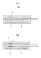
- a liquid junction structure of a sheet type reference electrode having the basic construction as described at the beginning is characterized by a hydrophilic porous thin film X covering the liquid junction surface B of the gelatinized internal solution G or the liquid junction member E connected to said gelatinized internal solution G for the sample solution as shown in Figs. 1(A) and (B).
- the liquid junction surface B of the gelatinized internal solution G or the liquid junction member E connected to the gelatinized internal solution G for the sample solution is covered or coated respectively with the hydrophilic porous thin film X so that there is no direct contact with the sample solution and the entire thin film X takes part in the control of the diffusion of ions from the gelatinized internal solution G, whereby the quantity of the diffusing ions can be always maintained constant for a long time regardless of the concentration of the gelatinized internal solution G.
- the water-evaporation inhibitor such as glycerine
- the surface of the hydrophilic porous thin film X does not dry. Therefore, an ideal liquid junction portion is formed, so that the life time of the electrode and the accuracy of measurement can be remarkably improved.
- this hydrophilic porous thin film X can be easily mass-produced, so that it can be very inexpensively produced.
- Fig. 1(A) and Fig. 1(B) show rough longitudinal sectional views of a fundamental construction of a liquid junction structure in a reference electrode according to the present invention.
- Preferred embodiments of the sheet type reference electrode according to the present invention are shown in Figs. 2 to 10.
- Fig. 2 shows a disintegrated perspective view of a pH-measuring sheet type composite electrode according to the first preferred embodiment
- Fig. 3 shows a developed longitudinal sectional view of principal parts
- Fig. 4 shows a disintegrated perspective view of a pH-measuring sheet type composite electrode according to the second preferred embodiment
- Fig. 5 shows a developed longitudinal sectional view of principal parts of the pH-measuring sheet type composite electrode according to the second preferred embodiment
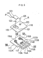
- FIG. 6 shows a disintegrated perspective view of an ion-measuring sheet type composite electrode according to the third preferred embodiment
- Fig. 7 shows a sectional view of Fig. 6 taken along the line VII-VII thereof
- Fig. 8 shows a sectional view of Fig. 6 taken along the line VIII-VIII thereof
- Fig. 9 shows a partially developed sectional view of a fourth preferred embodiment of the present invention
- Fig. 10 shows a partial sectional view of a cylindrical reference electrode according to a fifth preferred embodiment of the present invention
- Fig. 11 shows a rough longitudinal sectional view of a sheet type reference electrode (portion) having the conventional construction.
- the disintegrated perspective view shown in Fig. 2 and the developed longitudinal sectional view of principal parts shown in Fig. 3 relate to a first preferred embodiment of the sheet type composite electrode for measuring the pH according to the present invention.
- reference number 1 designates a substrate formed of a material (for example organic high molecular materials, such as polyethylene, polypropylene, polyethylene terephthalate, acrylic resin and polyfluoroethylene, and inorganic materials, such as silica glass and pyrex glass) having a sufficiently high electrical insulating property even though it is immersed in a solution containing electrolytes (in the present preferred embodiment a polyethylene terephthalate plate) and provided with two pairs of electrodes (an inside pair of electrodes and an outside pair of electrodes) 2A,2B, 3A, 3B sticking to the lower surface side thereof by depositing metals selected from the group consisting of electrically conductive Ag, Cu, Au, Pt and the like and alloys thereof or a paste comprising said metals or semiconductors, such as IrO2 and SnO2, by physical plating methods, such as the vacuum vapour deposition method and the CVD method, or chemical plating methods, such as the electrolytic method and the nonelectro
- a material for example
- a base end portion positioned at one end edge portion of the substrate 1 in these electrodes 2A, 2B, 3A, 3B is formed as lead portions 4A, 4B, 5A, 5B, respectively.
- Other nearly circular pointed end portions positioned at nearly in the central portion of the substrate 1 in the outer pair of electrodes 2A, 2B are formed as internal electrode portions 6A, 6B coated with an electrode material, such as AgCl, (by means of physical plating methods, chemical plating methods, printing methods or the like in the same manner as the above described), one internal electrode portion 6A (corresponding to the pH-measuring electrode portion P) being provided with a through hole 7, of which the inside surface is subjected to an electrifying treatment so that an electrode-like through hole is formed at the central portion thereof, and the other internal electrode portion 6B (corresponding to the reference electrode portion R) being provided with a through hole 8 at the vicinity thereof.
- an electrode material such as AgCl
- Reference number 7a designates the electrified portion of the through hole 7.
- a temperature-compensating electrode portion 9, such as a thermistor, is provided by extending over the other pointed end portions positioned at approximately the central portion of said substrate 1 of the inner pair of electrodes 3A, 3B.
- Reference mark X designates a hydrophilic porous thin film provided on the upper surface of said substrate 1 provided with a rectangular hole 10 formed at that place corresponding to said through hole 7 formed in the substrate 1 having the circumferential electrified portion 7a.
- a hydrophilic polypropylene film (DURAGURD® No. 3400, thickness: 25 microns, the largest hole diameter: 0.02 x 0.2 microns) is used.
- the hydrophilic porous thin film X having said through hole 8 is laminated on the upper surface of the substrate 1 by the hot melting method using an adhesive (for example, polyolefine adhesives, silicon resin adhesives and the like) which provide for securing sufficiently high electrical insulating properties (for example, 10 M ⁇ or more).
- an adhesive for example, polyolefine adhesives, silicon resin adhesives and the like
- the material of said hydrophilic porous thin film X comprises materials selected from PVC, polycarbonate, polyester, ABS, polytetrafluoroethylene, polyurethane, cellulose, cellulose acetate, polyacrylonitril, polymethylmethacrylate, polyethylene vinyl acetate and polysulfone, in addition to the above described polyolefine polymers, such as polypropylene and polyethylene.
- hydrophobic materials can be used by subjecting them to a H2O plasma treatment and a silane coupling treatment to impart the hydrophilic property.
- said hydrophilic porous thin film X is not limited to a one-layer structure.
- a multi-layer structure comprising a laminated plurality of hydrophilic porous thin films having the same one pore-diameter of different pore-diameters may be used.
- the quantity of ions diffused can be more easily and accurately controlled.
- Reference number 11 designates a first support layer formed of a material having a sufficiently high electrical insulating property in the same manner as said substrate 1 (in the present preferred embodiment it is polyethylene terephthalate), provided with through holes 12, 13 formed at places corresponding to the through holes 7, 8 formed in said substrate 1 and a rectangular portion 14 formed in the circumference of the upper side of said through hole l2, said first support layer is provided on the upper surface of said hydrophilic porous thin film X by for example the screen printing method of the hot melting method using an adhesive (for example, polyolefine adhesives, silicon resin adhesives and the like) which provide for securing a sufficiently high electrical insulating property (for example, 10 M ⁇ or more) or the like.
- the upper surface of this first support layer 11 is also subjected to the grafting process and the anchoring treatment by a silane coupling agent and the like.
- said hydrophilic porous thin film X may be pre-laminated on the lower surface of this first support layer.
- Reference number 15 designates a second support layer formed of a material having a sufficiently high electrical insulating property in the same manner as the substrate 1 and the first support layer 11 (in the present preferred embodiment it is polyethylene terephthalate), provided with through holes 16, 17 formed at that places corresponding to the internal electrode portion 6B of the reference electrode R and the through hole 8 formed in said substrate 1.
- the second support layer is provided on the lower surface of said substrate 1 in the same manner as said first support layer 11.
- Reference number 18 designates a gelatinized internal solution to be filled in the through hole 12 of said first support layer 17 to come into contact with the pH-measuring electrode portion P.
- Said gelatinized internal solution 18 is obtain-ed by adding a gelatinizer (for example, agar-agar, gelatine, glue, alginic acid, various kinds of water-absorbing polymers and the like) and a water-evaporation inhibitor (for example, glycerine, ethylene glycol and the like) to a basic internal solution obtained by adding a phosphoric acid buffer solution to a 3.3 M aqueous solution of KCl supersaturated with AgCl and molding the resulting mixture into a disc-like shape.
- a gelatinizer for example, agar-agar, gelatine, glue, alginic acid, various kinds of water-absorbing polymers and the like
- a water-evaporation inhibitor for example, glycerine, ethylene glyco
- This gelatinized internal solution 18 is filled into the through hole 12 by heating to convert it into a paste and printed by the screen printing method and the like so that its upper surface may slightly project over the upper surface of said first support layer 11.
- This gelatinized internal solution 18 is tightly sealed up in the through hole 12 and connected with the internal electrode portion 6A by the electrified portion 7a of the through hole 7 by sticking the lower of surface of a flat plate-like pH-response membrane 19 formed to have a predetermined size to the upper surface of the gelatinized internal solution 18.
- reference number 20 designates an adhesive having a sufficiently high electrical insulating property (for example, organic high molecular adhesives, such as silicon adhesives, epoxy adhesives and urethane adhesives) which provides sufficiently high electrical insulating properties for fixedly mounting said gelatinized internal solution 18 in the rectangular portion 14 of said first support layer along the circumference thereof.
- a sufficiently high electrical insulating property for example, organic high molecular adhesives, such as silicon adhesives, epoxy adhesives and urethane adhesives
- Reference mark G designates a relatively large rectangular shaped gelatinized internal solution for the use in the reference electrode portion to be filled into a bottom case 21 having the same composition as the gelatinized internal solution 18 of said pH-measuring electrode portion P and brought into contact with not only the internal electrode portion 6B through the through hole 16 of said second support layer but also with the lower surface of said hydrophilic porous thin film X through the through hole 17 of the second support layer (so that each portion may be risen).
- this surface portion, where the gelatinized internal solution G is brought into contact with the hydrophilic porous thin film X is herein called the liquid junction surface B.
- Reference number 22 designates a frame member fixedly mounted on the upper surface of the circumference of said first support layer 12 and provided with a sample solution-dropping portion C formed on the internal side thereof.
- the liquid junction surface B of the gelatinized internal solution G at the position of the reference electrode portion R is covered with the hydrophilic porpous thin film X, so that it is not in direct contact with the sample solution added into the sample solution-dropping portion C. Accordingly, the diffusion of ions from the gelatinized internal solution G can be surely controlled by the thin film X to maintain the quantity of ions diffusing at a constant value for a long time. As a result, a long life time of the electrode and an accurate measurement can be remarkably improved.
- a hydrophilic porous thin film X is laminated on the upper surface of the first support layer 12
- a liquid junction member E formed of a columnar gel-impregnated hydrophilic high molecular porous material is provided so as to extend over the through hole 12 of the first support layer 1, the through hole 8 of the substrate 1 and the through hole 17 of the second support layer 15 in an inserted manner, the liquid junction surface B, which is the upper surface of the liquid junction member E, is brought into contact with the lower surface of said hydrophilic porous thin film X, and the lower surface of the liquid junction member E is brought into contact with the gelatinized internal solution G at the position of the reference electrode R.
- This liquid junction member E has been disclosed in detail in the Japanese Utility Model Application No. Sho. 61-191498 filed by the present applicant.
- the liquid junction member E is obtained by impregnating a sintered molded product of olefinic high polymer powders having the nearly same mechanical strength as for example polyolefine and a hydrophilicity due to a transformation treatment (for example SUNFINE AQ® - manufactured by Asahi Kasei Kogyo Co., Ltd.) as a hydrophilic high molecular porous material formed by sintering and molding chemically stabilized hydrophilic high molecular powders with a gelatinized composition, which does not dry out when it is left unattended in the air, such as a water-containing jelly mainly comprising sodium salt of an acrylic polymer, (for example, U-jelly® - manufactured by Showa Denko Co., Ltd.).
- a transformation treatment for example SUNFINE AQ® - manufactured by Asahi Kase
- the liquid junction structure in the sheet type reference electrode exhibits superior effects in that the quantity of ions diffusing from the gelatinized internal solution can be very satisfactori severelyly controlled, whereby obtaining a remarkable improvement in view of the life time of electrode and accuracy of the measurement eventhough a remarkably simple and superior in mass-productivity means is used in that a liquid junction surface of the gelatinized internal solution or a liquid junction member connected to the gelatinized internal solution for a sample solution is covered with a hydrophilic porous thin film.
- Figs. 6 to 8 show a sheet type composite electrode for measuring the pH.
- reference mark 111 designates a substrate formed of a material (in the present preferred embodiment it is a polyethylene terephthalate plate) having a sufficiently high electrical insulating property even when it immersed in a solution comprising electrolytes, such as organic high molecular materials, for example polyethylene, polypropylene, polyethylene terephthalate, acryl, polyfluoroethylene and the like, and an inorganic material, for example silica glass, pyrex glass and the like which is provided with two pairs of electrodes 112A, 112B, 113A, 113B (inside pair of electrodes and outside pair of electrodes) formed by sticking a metal selected from the group consisting of electrically conductive Ag, Cu, Au, Pt and the like, alloys thereof and the like, or a paste including said metal, or a semiconductor, such as IrO2 and SnO2, to the upper surface of the substrate 111 by a physical plating method, such as vacuum deposition method and CVD method, or
- each electrode 112A, 112B, 113A, 113B positioned at one end edge portion of the substrate 111 is formed as the lead portions 114A, 114B, 115A, 115B.
- the other nearly circular pointed end portion positioned at the nearly central portion in the outside pair of electrodes 112A, 112B of said substrate 111 are formed as the internal electrode portions 116A and 116B coated with an electrode material, such as AgCl, (by physical plating method or chemical plating methods or printing methods in the same manner as above described) and a temperature-compensating electrode portion 117 is provided extending over the other pointed end portions positioned at the nearly central portion of said substrate 111 between the inside pair of electrodes 113A, 113B.
- a thermistor and the like are used as said temperature-compensating electrode portion 117.
- Reference number 118 designates a support layer provided on the upper surface of the substrate 111 formed of a material having a sufficiently high electrical insulating property in the same manner as the substrate 111 (in the present preferred embodiment it is a polyethylene terephthalate layer) and with a rectangular portion 121 formed on the upper surface side thereof. Said portion 121 includes a through hole 119. Through holes 119, 120 are provided at places corresponding to the internal electrode portions 116A, 116B, respectively, formed in the substrate 111.
- This support layer 118 is obtained by for example the screen printing method or the heat fusion treatment using an adhesive (for example, polyolefine adhesives, silicon resin adhesives and the like) which are capable of securing a sufficiently high electrical insulating property (for example, 10 M ⁇ or more). Also the upper surface of the support layer 118 is subjected to the grafting process and the anchoring process by a silane coupling agent and the like.
- an adhesive for example, polyolefine adhesives, silicon resin adhesives and the like
- a sufficiently high electrical insulating property for example, 10 M ⁇ or more
- Reference numeral 122 designates a gelatinized internal solution filled in the through hole 119 of the support layer 118 formed in for example a disc-like shape by adding a gelatinizer (for example, agar-agar, gelatine, glue, alginic acid, various kinds of acrylic water-absorbing polymer and the like) and a gel-evaporation inhibitor (for example, glycerine, ethylene glycol and the like) to a basic internal solution obtained by for example adding a phosphoric acid buffer solution to a 3.3 M aqueous solution of KCl supersaturated with AgCl.
- a gelatinizer for example, agar-agar, gelatine, glue, alginic acid, various kinds of acrylic water-absorbing polymer and the like
- a gel-evaporation inhibitor for example, glycerine, ethylene glycol and the like
- the gelatinized internal solution122 is filled into the through hole 119 by heating it under conversion into a paste and printing the resulting paste by the screen printing method so that the upper surface thereof may slightly project over the upper surface of the support layer 118 under free conditions and may be sealed up tightly in the through hole 119 by providing a flat plate-like selective ion-response membrane 123, which is formed so as to have the size of the rectangular portion 121, so that the lower surface of the flat plate-like selective ion-response membrane 123 may be contacted to the upper surface thereof, and brought into contact with the internal electrode portion 116A by obtaining the pH-measuring electrode P.
- Reference numeral 124 designates an adhesive, for example high molecular adhesives such as a silane coupling agent having a sufficiently high electrical insulating property for sticking the selective ion-response membrane 123 to the support layer ll8 along the circumference thereof.
- high molecular adhesives such as a silane coupling agent having a sufficiently high electrical insulating property for sticking the selective ion-response membrane 123 to the support layer ll8 along the circumference thereof.
- Reference numeral 125 designates a gel-impregnated hydrophilic high molecular porous material which is to be inserted into another hole 120 provided in the support layer 118. Said gel-impregnated hydrophilic high molecular porous material 125 functions as a combination of the liquid junction and internal solution portion of the reference electrode R.
- the gel-impregnated hydrophilic high molecular porous material 125 is formed by impregnating a hydrophilic high molecular porous material, which is obtained by sintering and molding chemically stabilized hydrophilic high molecular particles, for example sintered and molded olefinic high polymeric powders having a mechanical strength nearly equal to that of polyolefines, to which the hydrophilicity is imparted by a modification treatment (for example, SUNFINE AQ®, manufactured by Asahi Kasei Kogyo Co., Ltd.) with a gelatinized composition which does not deposite KCl. Moreover, the wetness from the surface of the porous material is maintained by said impregnation, that it not dry out, even when it is left unattended in the air.
- the above described gelatinized composition is obtained by dissolving a high moisture-preserving water-containing jelly mainly comprising acrylic polymers (for example, U-jelly®, manufactured by Showa Denko Co., Ltd.) in the internal solution obtained by for example adding a phosphoric acid buffer solution to a 3.3 M aqueous solution of KCl supersaturated with AgCl and then adding a gelatinizer selected from the group consisting of agar-agar, gelatine, glue, alginic acid and the like to the resulting solution.
- a gelatinizer selected from the group consisting of agar-agar, gelatine, glue, alginic acid and the like to the resulting solution.
- This transparent water-containing jelly mainly comprises the sodium salt of an acrylic polymer having a remarkably high compatibility with other aqueous solutions and a remarkably superiority to conventional moisture-evaporation inhibitors, such as glycerine and propylene glycol, a moisture-preserving function and vapour pressure equilibrium-preserving function due to the formation of cluthrate by hydrogen bonds between polymeric molecules.
- this jelly can maintain a sufficient lubricity for a long time without drying out even when it is exposed to air for a long time so that the adsorption of water in the air and dewing do hardly occur and as a result, its surface can be always maintained under a moderate wet conditions according to the invention.
- the combination of the liquid junction and the internal solution portion of a side of the reference electrode R is formed of the gel-impregnated hydrophilic high molecular porous material 125, it may be formed in such a manner as shown in Fig. 9.
- reference number 130 designates a gelatinized internal solution having the same composition as the gelatinized internal solution 122 described in the above described preferred embodiment which is provided on the lower surface of the substrate 111.
- substrate 111 is provided with a through hole 131 formed at a place corresponding to the internal electrode portion 116B (of a side of the reference electrode R) and the gelatinized internal solution 130 is brought into contact with the internal electrode portion 116B by the through hole 131.
- substrate 111 and the support layer 118 are provided with through holes 132, 133 at corresponding positions so as to communicate with each other and a gel-impregnated hydrophilic high molecular porous material 134 formed in the same manner as the above described gel-impregnated hydrophilic high molecular porous materials 125 is inserted into said through holes 132, 133 so that the lower end thereof may be brought into contact with the gelatinized internal solution 130.
- reference number 135 designates a bottom case.
- the gel-impregnated hydrophilic high molecular porous material 134 as the liquid junction portion is connected to the lead portion 112B by the gelatinized internal solution 130.
- Fig. 10 shows the fifth preferred embodiment of the invention.
- reference number 101 designates a support tube formed of glass or plastics having inside an internal solution 102, such as an aqueous solution of KCl, which is provided with an internal electrode 104 formed in the end portion of a glass tube 103.
- Reference numeral 105 designates a supply port of the internal solution 102.
- Reference number 106 designates a gel-impregnated hydrophilic high molecular porous material as a liquid junction portion formed in the end portion of the support tube 101. This material 106 is formed in the same manner as the above described gel-impregnated hydrophilic high molecular porous materials 125, 134 and inserted into hole 107 formed in the end portion of the support tube 101.
- the gel-impregnated hydrophilic high molecular porous material obtained by impregnating the chemically stabilized hydrophilic high molecular porous material with the gelatinized composition, which does not dry out even when left unattended in the air, is used as the liquid junction portion 106, not only the liquid junction portion 106 is stabilized in shape but also the internal solution does not flow out, whereby it becomes unnecessary to replenish the internal solution 102.
- the gelatinized composition with which the hydrophilic high molecular porous material is impregnated, does not dry out, meshes of the liquid junction portion can be prevented from being clogged and the measurement can be always carried out under wet conditions, and as a result, the stabilized measurement can be obtained.
- the gel-impregnated hydrophilic high molecular porous material constructed in the above described manner does not swell and reduce its strength and it is superior in size stability, it can be easily incorporated into the support member 101 formed of glass and plastics.
- the gel-impregnated hydrophilic high molecular porous material can be formed onto the support member 101 as the liquid junction portion 106 by the use of suitable adhesives according to materials of the support member 101.
- the reference electrode when a gel-impregnated hydrophilic high molecular porous material obtained by impregnating a chemically stabilized hydrophilic high molecular porous material with a gelatinized composition which does not dry out even when it is left in the air is used as liquid junction portion, the reference electrode has advantages in that it can be surely preserved and a stabilized measurement can be obtained.
Landscapes
- Chemical & Material Sciences (AREA)
- Life Sciences & Earth Sciences (AREA)
- Health & Medical Sciences (AREA)
- Biochemistry (AREA)
- General Physics & Mathematics (AREA)
- Electrochemistry (AREA)
- Physics & Mathematics (AREA)
- Analytical Chemistry (AREA)
- Molecular Biology (AREA)
- General Health & Medical Sciences (AREA)
- Chemical Kinetics & Catalysis (AREA)
- Immunology (AREA)
- Pathology (AREA)
- Investigating Or Analysing Biological Materials (AREA)
- Measurement Of The Respiration, Hearing Ability, Form, And Blood Characteristics Of Living Organisms (AREA)
- Investigating Or Analyzing Materials By The Use Of Electric Means (AREA)
- Battery Electrode And Active Subsutance (AREA)
- Electric Double-Layer Capacitors Or The Like (AREA)
Applications Claiming Priority (4)
| Application Number | Priority Date | Filing Date | Title |
|---|---|---|---|
| JP1986191498U JPH0416216Y2 (de) | 1986-12-11 | 1986-12-11 | |
| JP191498/86U | 1986-12-11 | ||
| JP168375/87 | 1987-07-04 | ||
| JP62168375A JPH0762660B2 (ja) | 1987-07-04 | 1987-07-04 | シ−ト型比較電極における液絡構造 |
Publications (3)
| Publication Number | Publication Date |
|---|---|
| EP0271101A2 true EP0271101A2 (de) | 1988-06-15 |
| EP0271101A3 EP0271101A3 (en) | 1990-03-07 |
| EP0271101B1 EP0271101B1 (de) | 1996-03-20 |
Family
ID=26492096
Family Applications (1)
| Application Number | Title | Priority Date | Filing Date |
|---|---|---|---|
| EP87118326A Expired - Lifetime EP0271101B1 (de) | 1986-12-11 | 1987-12-10 | Referenzelektrode |
Country Status (5)
| Country | Link |
|---|---|
| US (1) | US4980043A (de) |
| EP (1) | EP0271101B1 (de) |
| KR (1) | KR900005243B1 (de) |
| CN (1) | CN1010254B (de) |
| DE (1) | DE3751746D1 (de) |
Cited By (4)
| Publication number | Priority date | Publication date | Assignee | Title |
|---|---|---|---|---|
| EP0321737A3 (en) * | 1987-12-22 | 1990-08-01 | Abbott Laboratories | Miniaturized reference electrodes |
| EP0449166A3 (en) * | 1990-03-30 | 1991-11-27 | Centro Sviluppo Materiali S.P.A. | Device for measuring the ph of liquid films |
| EP0597203A3 (en) * | 1992-09-14 | 1995-12-13 | Siemens Ag | Reference electrode. |
| EP3088879A1 (de) * | 2015-04-30 | 2016-11-02 | Stichting IMEC Nederland | Bezugselektrode mit einer porenmembran |
Families Citing this family (18)
| Publication number | Priority date | Publication date | Assignee | Title |
|---|---|---|---|---|
| US5310473A (en) * | 1986-03-19 | 1994-05-10 | Horiba Ltd. | Removable sample testing member for use in measuring ion concentration |
| JPH03127252U (de) * | 1990-04-02 | 1991-12-20 | ||
| US5246576A (en) * | 1990-12-10 | 1993-09-21 | Ppg Industries, Inc. | Cathode in a layered circuit and electrochemical cell for a measurement of oxygen in fluids |
| KR970001146B1 (ko) * | 1993-07-16 | 1997-01-29 | 엘지전자 주식회사 | 가스측정용 바이오센서 및 그 제조방법 |
| US5505826A (en) * | 1994-11-30 | 1996-04-09 | Haglin; Patrick G. | Hydrophilic anode corrosion control system |
| DE19917830A1 (de) | 1999-04-13 | 2000-10-19 | Senslab Gmbh | Planare offene Referenzelektrode zur Anwendung in voltammetrischen Meßketten |
| US6432296B1 (en) * | 1999-09-24 | 2002-08-13 | Daniel S. Daniel | Polymeric compositions for ion-selective electrodes |
| US7456025B2 (en) * | 2001-08-28 | 2008-11-25 | Porex Corporation | Sintered polymer membrane for analyte detection device |
| DE10207624A1 (de) * | 2002-02-22 | 2003-09-04 | Mettler Toledo Gmbh | Druckresistente Bezugselektrode für elektochemische Messungen |
| US7373195B2 (en) * | 2004-07-30 | 2008-05-13 | Medtronic, Inc. | Ion sensor for long term use in complex medium |
| US20100116025A1 (en) * | 2006-09-28 | 2010-05-13 | U.S. Genomics, Inc | Air sampler |
| KR101374888B1 (ko) * | 2007-07-20 | 2014-03-13 | 한양대학교 산학협력단 | 접착조성물, 접착조성물의 제조방법, 표시장치 및표시장치의 제조방법 |
| US8535499B2 (en) * | 2010-02-09 | 2013-09-17 | Stichting Imec Nederland | Microfabricated liquid-junction reference electrode |
| CN102971621B (zh) * | 2010-08-27 | 2015-01-21 | 株式会社堀场制作所 | 参比电极 |
| KR20150013146A (ko) | 2012-04-19 | 2015-02-04 | 로익스 다이어그노스틱스, 아이엔씨. | 다층겔 |
| CN102967639A (zh) * | 2012-07-11 | 2013-03-13 | 哈尔滨工程大学 | 适用于深海高静水压力环境下的长寿命参比电极 |
| AU2013334616A1 (en) | 2012-10-23 | 2014-06-26 | Aytu Bioscience, Inc. | Methods and systems for measuring and using the oxidation-reduction potential of a biological sample |
| US10288582B2 (en) | 2016-01-12 | 2019-05-14 | Analog Devices Global | Integrated ion sensing apparatus and methods |
Family Cites Families (8)
| Publication number | Priority date | Publication date | Assignee | Title |
|---|---|---|---|---|
| US3705089A (en) * | 1970-09-28 | 1972-12-05 | Gen Electric | Reference electrode half cell |
| JPS5198089A (en) * | 1975-02-25 | 1976-08-28 | Hikakudenkyokuno ekirakubu | |
| DE3100302A1 (de) * | 1980-01-11 | 1981-12-10 | List, Hans, Prof. Dipl.-Ing. Dr.Dr.h.c., Graz | Elektrochemische referenzelektrode |
| FR2541462A1 (fr) * | 1983-02-17 | 1984-08-24 | Texaim | Electrode de reference electrochimique miniature |
| JPS6396453U (de) * | 1986-12-11 | 1988-06-22 | ||
| DE3789491T2 (de) * | 1986-11-27 | 1994-10-20 | Horiba Ltd | Plattenförmige Glaselektrode. |
| JPH0446205Y2 (de) * | 1986-12-11 | 1992-10-29 | ||
| JPS63225164A (ja) * | 1987-03-16 | 1988-09-20 | Horiba Ltd | イオン測定用シート型複合電極 |
-
1987
- 1987-11-24 US US07/124,903 patent/US4980043A/en not_active Expired - Fee Related
- 1987-11-26 KR KR1019870013382A patent/KR900005243B1/ko not_active Expired
- 1987-12-10 CN CN87107350A patent/CN1010254B/zh not_active Expired
- 1987-12-10 EP EP87118326A patent/EP0271101B1/de not_active Expired - Lifetime
- 1987-12-10 DE DE3751746T patent/DE3751746D1/de not_active Expired - Lifetime
Cited By (4)
| Publication number | Priority date | Publication date | Assignee | Title |
|---|---|---|---|---|
| EP0321737A3 (en) * | 1987-12-22 | 1990-08-01 | Abbott Laboratories | Miniaturized reference electrodes |
| EP0449166A3 (en) * | 1990-03-30 | 1991-11-27 | Centro Sviluppo Materiali S.P.A. | Device for measuring the ph of liquid films |
| EP0597203A3 (en) * | 1992-09-14 | 1995-12-13 | Siemens Ag | Reference electrode. |
| EP3088879A1 (de) * | 2015-04-30 | 2016-11-02 | Stichting IMEC Nederland | Bezugselektrode mit einer porenmembran |
Also Published As
| Publication number | Publication date |
|---|---|
| KR900005243B1 (ko) | 1990-07-21 |
| EP0271101A3 (en) | 1990-03-07 |
| EP0271101B1 (de) | 1996-03-20 |
| CN1010254B (zh) | 1990-10-31 |
| US4980043A (en) | 1990-12-25 |
| KR880008018A (ko) | 1988-08-30 |
| DE3751746D1 (de) | 1996-04-25 |
| CN87107350A (zh) | 1988-06-22 |
Similar Documents
| Publication | Publication Date | Title |
|---|---|---|
| EP0271101A2 (de) | Referenzelektrode | |
| US4214968A (en) | Ion-selective electrode | |
| US6287438B1 (en) | Sampling system for analytes which are fluid or in fluids and process for its production | |
| US5468374A (en) | Miniaturized sensor component for measuring concentrations of substances in liquids, and method of manufacturing such a component | |
| US4966671A (en) | Method and apparatus for electrochemical analysis | |
| US9696273B2 (en) | Reference half-cell and electrochemical sensor with the reference half-cell | |
| US5653864A (en) | Protein biosensor and method for protein measurement with the same | |
| TWI328114B (en) | Heterogeneous membrane electrodes and method for using the same | |
| JPS6020700B2 (ja) | 電極の対を支持するフレ−ム | |
| WO2003098205A1 (en) | Ion exchange membranes and dissolved gas sensors | |
| JPS584981B2 (ja) | イオン選択性電極 | |
| JP2001506366A (ja) | 電気化学センサー | |
| KR900005221B1 (ko) | 이온측정용 시이트형 전극 | |
| KR100943114B1 (ko) | 카트리지식 전기 화학 분석 장치 및 방법 | |
| JP2001514760A (ja) | サブミニアチュアスルーホールを備えたワイアリングサブストレートの製造方法 | |
| JP2003503702A (ja) | 汎用トランスデューサ | |
| AU5944490A (en) | Electrochemical cell, reference electrode and electrochemical method | |
| EP0271100B1 (de) | Blattähnliche Elektrode | |
| JPH0416216Y2 (de) | ||
| US5211830A (en) | Sheet-type electrode for use in the measurement of ion concentration | |
| CA1116696A (en) | Ion-selective electrode | |
| EP0103031B1 (de) | Elektrochemische Zelle zur Bestimmung einer besonderen Eigenschaft oder Komponente von Flüssigkeiten | |
| CN115406946B (zh) | 一次性即时检测卡片及传感器芯片的po2电极制备方法 | |
| JPH0762660B2 (ja) | シ−ト型比較電極における液絡構造 | |
| CA1093641A (en) | Ion-selective electrode |
Legal Events
| Date | Code | Title | Description |
|---|---|---|---|
| PUAI | Public reference made under article 153(3) epc to a published international application that has entered the european phase |
Free format text: ORIGINAL CODE: 0009012 |
|
| AK | Designated contracting states |
Kind code of ref document: A2 Designated state(s): CH DE ES FR GB IT LI NL |
|
| PUAL | Search report despatched |
Free format text: ORIGINAL CODE: 0009013 |
|
| AK | Designated contracting states |
Kind code of ref document: A3 Designated state(s): CH DE ES FR GB IT LI NL |
|
| 17P | Request for examination filed |
Effective date: 19900523 |
|
| 17Q | First examination report despatched |
Effective date: 19911216 |
|
| GRAH | Despatch of communication of intention to grant a patent |
Free format text: ORIGINAL CODE: EPIDOS IGRA |
|
| GRAA | (expected) grant |
Free format text: ORIGINAL CODE: 0009210 |
|
| AK | Designated contracting states |
Kind code of ref document: B1 Designated state(s): CH DE ES FR GB IT LI NL |
|
| PG25 | Lapsed in a contracting state [announced via postgrant information from national office to epo] |
Ref country code: NL Free format text: LAPSE BECAUSE OF FAILURE TO SUBMIT A TRANSLATION OF THE DESCRIPTION OR TO PAY THE FEE WITHIN THE PRESCRIBED TIME-LIMIT Effective date: 19960320 Ref country code: LI Effective date: 19960320 Ref country code: FR Effective date: 19960320 Ref country code: CH Effective date: 19960320 Ref country code: IT Free format text: LAPSE BECAUSE OF FAILURE TO SUBMIT A TRANSLATION OF THE DESCRIPTION OR TO PAY THE FEE WITHIN THE PRE;WARNING: LAPSES OF ITALIAN PATENTS WITH EFFECTIVE DATE BEFORE 2007 MAY HAVE OCCURRED AT ANY TIME BEFORE 2007. THE CORRECT EFFECTIVE DATE MAY BE DIFFERENT FROM THE ONE RECORDED.SCRIBED TIME-LIMIT Effective date: 19960320 |
|
| REF | Corresponds to: |
Ref document number: 3751746 Country of ref document: DE Date of ref document: 19960425 |
|
| PG25 | Lapsed in a contracting state [announced via postgrant information from national office to epo] |
Ref country code: DE Effective date: 19960621 |
|
| PG25 | Lapsed in a contracting state [announced via postgrant information from national office to epo] |
Ref country code: ES Free format text: LAPSE BECAUSE OF FAILURE TO SUBMIT A TRANSLATION OF THE DESCRIPTION OR TO PAY THE FEE WITHIN THE PRESCRIBED TIME-LIMIT Effective date: 19960701 |
|
| EN | Fr: translation not filed | ||
| NLV1 | Nl: lapsed or annulled due to failure to fulfill the requirements of art. 29p and 29m of the patents act | ||
| REG | Reference to a national code |
Ref country code: CH Ref legal event code: PL |
|
| PLBE | No opposition filed within time limit |
Free format text: ORIGINAL CODE: 0009261 |
|
| STAA | Information on the status of an ep patent application or granted ep patent |
Free format text: STATUS: NO OPPOSITION FILED WITHIN TIME LIMIT |
|
| 26N | No opposition filed | ||
| PGFP | Annual fee paid to national office [announced via postgrant information from national office to epo] |
Ref country code: GB Payment date: 19971201 Year of fee payment: 11 |
|
| PG25 | Lapsed in a contracting state [announced via postgrant information from national office to epo] |
Ref country code: GB Free format text: LAPSE BECAUSE OF NON-PAYMENT OF DUE FEES Effective date: 19981210 |
|
| GBPC | Gb: european patent ceased through non-payment of renewal fee |
Effective date: 19981210 |