EP0273496B1 - Magnetkopf mit einem elektro-chemisch inerten Spalt aus hartem Material - Google Patents
Magnetkopf mit einem elektro-chemisch inerten Spalt aus hartem Material Download PDFInfo
- Publication number
- EP0273496B1 EP0273496B1 EP87202367A EP87202367A EP0273496B1 EP 0273496 B1 EP0273496 B1 EP 0273496B1 EP 87202367 A EP87202367 A EP 87202367A EP 87202367 A EP87202367 A EP 87202367A EP 0273496 B1 EP0273496 B1 EP 0273496B1
- Authority
- EP
- European Patent Office
- Prior art keywords
- layers
- magnetic
- magnetic head
- gap
- layer
- Prior art date
- Legal status (The legal status is an assumption and is not a legal conclusion. Google has not performed a legal analysis and makes no representation as to the accuracy of the status listed.)
- Expired - Lifetime
Links
Images
Classifications
-
- G—PHYSICS
- G11—INFORMATION STORAGE
- G11B—INFORMATION STORAGE BASED ON RELATIVE MOVEMENT BETWEEN RECORD CARRIER AND TRANSDUCER
- G11B5/00—Recording by magnetisation or demagnetisation of a record carrier; Reproducing by magnetic means; Record carriers therefor
- G11B5/127—Structure or manufacture of heads, e.g. inductive
- G11B5/187—Structure or manufacture of the surface of the head in physical contact with, or immediately adjacent to the recording medium; Pole pieces; Gap features
- G11B5/23—Gap features
-
- G—PHYSICS
- G11—INFORMATION STORAGE
- G11B—INFORMATION STORAGE BASED ON RELATIVE MOVEMENT BETWEEN RECORD CARRIER AND TRANSDUCER
- G11B5/00—Recording by magnetisation or demagnetisation of a record carrier; Reproducing by magnetic means; Record carriers therefor
- G11B5/40—Protective measures on heads, e.g. against excessive temperature
-
- G—PHYSICS
- G11—INFORMATION STORAGE
- G11B—INFORMATION STORAGE BASED ON RELATIVE MOVEMENT BETWEEN RECORD CARRIER AND TRANSDUCER
- G11B5/00—Recording by magnetisation or demagnetisation of a record carrier; Reproducing by magnetic means; Record carriers therefor
- G11B5/127—Structure or manufacture of heads, e.g. inductive
- G11B5/187—Structure or manufacture of the surface of the head in physical contact with, or immediately adjacent to the recording medium; Pole pieces; Gap features
- G11B5/1875—"Composite" pole pieces, i.e. poles composed in some parts of magnetic particles and in some other parts of magnetic metal layers
- G11B5/1877—"Composite" pole pieces, i.e. poles composed in some parts of magnetic particles and in some other parts of magnetic metal layers including at least one magnetic thin film
- G11B5/1878—"Composite" pole pieces, i.e. poles composed in some parts of magnetic particles and in some other parts of magnetic metal layers including at least one magnetic thin film disposed immediately adjacent to the transducing gap, e.g. "Metal-In-Gap" structure
-
- G—PHYSICS
- G11—INFORMATION STORAGE
- G11B—INFORMATION STORAGE BASED ON RELATIVE MOVEMENT BETWEEN RECORD CARRIER AND TRANSDUCER
- G11B5/00—Recording by magnetisation or demagnetisation of a record carrier; Reproducing by magnetic means; Record carriers therefor
- G11B5/127—Structure or manufacture of heads, e.g. inductive
- G11B5/187—Structure or manufacture of the surface of the head in physical contact with, or immediately adjacent to the recording medium; Pole pieces; Gap features
- G11B5/23—Gap features
- G11B5/235—Selection of material for gap filler
Definitions
- the invention relates to a magnetic head for recording, reproducing and/or erasing magnetic information in a track of a magnetic information carrier, comprising a magnetic core having two core limbs formed from a ferrite, at least one of which has a cladding layer of a magnetic material having a higher saturation magnetization than the ferrite, a non-magnetic gap present between the core limbs and a winding aperture having an electric coil wound around at least one of the core limbs.
- MIG head Metal-in-gap head
- MIG head Metal-in-gap head
- ferrites particularly monocrystalline Mn-Zn ferrites as magnetic core materials for magnetic heads because ferrites have a number of advantages. Such advantages are a high resistance to wear, a relatively high specific resistance and satisfactory magnetic properties relating to coercive force and permeability.
- Magnetic fields which are generated by a magnetic head at the area of the transducing gap in order to write information on a magnetic medium are directly dependent on the saturation magnetization of the material of the magnetic head core.
- Ferrites have a saturation magnetization which is sufficiently high to write information on conventional tapes such as CrO2 tapes having a coercive force H c of approximately 56KA/m (700 Oersted).
- H c coercive force
- conventional magnetic heads which exclusively have ferrite on either side of the transducing gap are less suitable.
- the magnetic fields which are generated by such magnetic heads to write information on a magnetic medium are in fact limited by the relatively low saturation magnetization of the ferrite. The strength of the writing field is therefore insufficiently high to ensure optimum writing of magnetic tapes having a high coercive force.
- This known magnetic head has sendust cladding layers. These soft magnetic layers are present on either side of the non-magnetic gap and are provided by sputtering on the core limbs connected together by means of a glass joint. The gap is composed in a manner not further described.
- a cladding layer may consist of a plurality of layers provided on one another as has already been proposed in the non-prepublished EP-A-00246706 in the name of Applicant.
- the non-magnetic gap consists of a glass layer and two SiO2-layers, which SiO2-layers extend between the glass layer and the cladding layers.
- the composition of the gap is to be effected at a temperature in the range between 500 and approximately 700°C due to the glass properties.
- Such a high composition temperature may, however, have several detrimental effects on the magnetic head provided with cladding layers.
- One of these detrimental results may be a deterioration of the magnetic properties of the soft-magnetic cladding layers.
- mechanical stresses may be created in the cladding layers at high temperatures, which stresses are so high that they cause fractures in the ferrite core limbs.
- the magnetic head according to the invention is characterized in that the gap is composed of the following layers: two first layers of a first metallic material provided vided on the core limbs, an insulation layer of an electrically insulating material being provided between the cladding layer and one of the first layers, and two second layers of a second metallic material provided on the first layers, which second layers are bonded to each other.
- the gap composed in the magnetic head according to the invention can be realized at temperatures in the range between 150 and 400°C. Inadmissible deteriorations of and inadmissible stresses in the cladding layers caused by temperature influences during manufacture can then be avoided.
- the insulation layer in the gap of the magnetic head according to the invention functions as an electrochemical and diffusion barrier between the soft-magnetic material, for example an alloy based on Ni, Fe or Fe, Al, Si, of the cladding layer and the metallic materials of the first and second layers so that an electrochemical interaction between the soft-magnetic material on the one hand and the metallic materials on the other hand is prevented.
- the gap is therefore electro-chemically inert.
- the first metallic material of the first layers serves as an adhesive material between the second metallic material of the second layers and the material of the insulation layer or the ferrite of one of the core limbs.
- the second layers themselves constitute the actual gap bonding and are bonded to each other by means of known techniques, for example thermocompression.
- the electrically insulating material of the insulation layer is preferably chosen from the group of oxides, nitrides and carbides such as TiO2, SO3N4 or TiC.
- the insulation layer provides an essential contribution to the hardness and the resistance to wear of the gap. It has been proved by experiment that in a magnetic head provided with two cladding layers the greater part of the gap consists of the insulation layers. The remaining part of the gap consists of the first and second layers of metallic materials. It is true that these layers are mechanically softer than the insulation layer, but due to their slight thickness compared with the overall gap length the influence on the total hardness of the gap is small. Very favourable results have been achieved with an embodiment of the magnetic head according to the invention in which SiO2 is used as an insulation layer material.
- a further favourable embodiment of the magnetic head according to the invention is characterized in that the first metallic material of the first layers is chosen from the group of Mo, Ti, Cr and NiCr. These first metallic materials are preferably combined with a second metallic material of the second layers chosen from the metals Au and Ag.
- a magnetic head obtained in this known manner has a gap which is exclusively composed of a pluraltiy of metal layers.
- a general drawback thereof is that such a gap, as compared with a gap consisting of glass and SiO2 layers, is mechanically soft so that the magnetic head is easily hollowed out.
- a magnetic head of the type described in the opening paragraph obtained by means of the above-mentioned known method, that is to say, having at least one cladding layer provided on the ferrite would also have the specific drawback of a possible electro-chemical interaction occurring between the soft-magnetic material of the cladding layers and the metal provided thereon so that corrosion of the gap and/or the cladding layer may occur.
- Another disadvantage of a gap consisting of only metal layers may be the occurrence of a diffusion between the cladding layers and the gap layers, resulting in a gap which is not magnetically sharp and which has not a very reproducible length.
- the known method is therefore unsuitable for manufacturing magnetic heads which have one or more cladding layers.
- a magnetic head having two ferrite core limbs is known from US Patent 3,672,045 in which the core limbs are joined to each other by means of layers of Cu, Au, Ag or Ti which are connected together by means of diffusion.
- a layer of a material having a low magnetic permeability selected from the group of Mo, W, silicon nitride Al, Ta, Cu, Au, tantalum nitride, SiO, Ag, glass and metal-ceramic material combinations is provided between the connection layers and the ferrite core limbs.
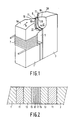
- Fig. 1 is a diagrammatic view of an embodiment of the magnetic head according to the invention.
- Fig. 2 is a larger cross-section, not to scale, taken on the line II-II of Figure 1.
- the magnetic head according to the invention is suitable for writing and reading magnetic tapes having high coercive forces and comprises a magnetic core consisting of two core limbs 1 and 3 in which a winding aperture 5 is provided. A coil 7 passing through the winding aperture 5 is wound around one of the core limbs.
- the core limbs 1 and 3 which are formed from a ferrite, for example a monocrystalline Mn-Zn ferrite, have contact surfaces 1A and 3A, respectively, on which a magnetic tape (not shown) is moved in the direction of the arrow A during operation of the magnetic head.
- a non-magnetic gap 9 extending as far as the contact surfaces 1A and 3A is present between the core limbs 1 and 3.
- the core limbs 1 and 3 each have core faces 1B and 3B, respectively, facing the gap 9 on which faces a cladding layer 11 is provided which consists of one or more materials having a higher saturation magnetization than the ferrite. Suitable materials are, for example Ni-Fe,based alloys such as Ni80Fe20, Fe-Si-Al-based alloys such as Fe 85.8 Si 9.2 Al 5.0 , amorphous alloys and combinations of the said alloys.
- the cladding layers 11 consist of Ni80Fe20, provided by sputtering.
- the gap 9 is composed of a number of layers of a non-magnetic material which together bond the core lims 1 and 3 to each other.
- an insulation layer 13 of SiO2 of the layers of the gap 9 is provided on each of the cladding layers 11.
- a first layer 15 of Mo is provided on each of the insulation layers 13 by means of sputtering and a second layer 17 of Au is provided on each of the first layers 15.
- the first layers 15 ensure the adhesion of the second layers 17 to the insulation layers 13, whilst the second layers 17 are bonded to each other by means of thermocompression.
- each insulation layer 13 was 0.09 ⁇ m and the layer thickness of each first and second layers 15 and 17 was 0.03/ ⁇ m.
- the thickness of the cladding layers 11 was 1.15/ ⁇ m.
- the gap 9 viewed widthwise, is perpendicular to the direction of propagation of the magnetic tape.
- the gap in the direction considered is not oriented perpendicularly to the said direction of propagation are of course also possible.
- the core faces 1B and 3B of the magnetic head are bounded by recesses 19 on either side of the magnetic head.
- the recesses 19 define the width of the gap 9 and partly extend into the tape contact face constituted by the contact faces 1A and 3A and partly into the side faces of the magnetic head.
Landscapes
- Engineering & Computer Science (AREA)
- Manufacturing & Machinery (AREA)
- Magnetic Heads (AREA)
Claims (6)
- Magnetkopf zum Aufzeichnen, Wiedergeben und/oder Löschen magnetischer Information in einer Spur eines magnetischen Aufzeichnungsträgers, mit:- einem Magnetkern mit zwei aus einem Ferrit gebildeten Kernteilen (1,3), von denen wenigstens einer mit einer Verkleidungsschicht (11) aus einem magnetischen Material mit einer höheren Sättigungsmagnetisierung als das Ferrit versehen ist,- einem zwischen den Kernteilen vorgesehenen nicht-magnetischen Spalt, und- einer Spulenkammer (5) mit einer um wenigstens eines der Kernteile liegenden elektrischen Spule (7),
dadurch gekennzeichnet, daß der Spalt aus den folgenden Schichten aufgebaut ist:- zwei auf den Kernteilen angebrachten ersten Schichten (15) aus einem ersten metallischen Material, wobei zwischen der Verkleidungsschicht (11) und einer der ersten Schichten eine Isolierschicht (13) aus einem elektrisch isolierenden Material vorgesehen ist, und- zwei auf den ersten Schichten angebrachten zweiten Schichten (17) aus einem zweiten metallischen Material, wobei die zweiten Schichten aneinander befestigt sind. - Magnetkopf nach Anspruch 1, dadurch gekennzeichnet, daß das elektrisch isolierende Material der Isolierschicht (13) aus der Gruppe von Oxiden, Nitriden und Karbiden gewählt worden ist.
- Magnetkopf nach Anspruch 1 oder 2, dadurch gekennzeichnet, daß das elektrische Isoliermaterial der Isolierschicht (13) Si0₂ ist.
- Magnetkopf nach Anspruch 1, 2 oder 3, dadurch gekennzeichnet, daß das erste metallische Material der ersten Schichten (15) aus der Gruppe von Mo, Ti, Cr und NiCr gewählt worden ist.
- Magnetkopf nach Anspruch 1, 2, 3 oder 4, dadurch gekennzeichnet, daß das zweite metallische Material der zweiten Schichten (17) aus den Metallen Au und Ag gewählt worden ist.
- Magnetkopf nach Anspruch 1, dadurch gekennzeichnet, daß die zweiten Schichten (l7) durch Thermokompression aneinander befestigt sind.
Applications Claiming Priority (2)
| Application Number | Priority Date | Filing Date | Title |
|---|---|---|---|
| NL8603078 | 1986-12-03 | ||
| NL8603078 | 1986-12-03 |
Publications (2)
| Publication Number | Publication Date |
|---|---|
| EP0273496A1 EP0273496A1 (de) | 1988-07-06 |
| EP0273496B1 true EP0273496B1 (de) | 1991-04-10 |
Family
ID=19848941
Family Applications (1)
| Application Number | Title | Priority Date | Filing Date |
|---|---|---|---|
| EP87202367A Expired - Lifetime EP0273496B1 (de) | 1986-12-03 | 1987-11-30 | Magnetkopf mit einem elektro-chemisch inerten Spalt aus hartem Material |
Country Status (5)
| Country | Link |
|---|---|
| US (1) | US4887177A (de) |
| EP (1) | EP0273496B1 (de) |
| JP (1) | JP2554111B2 (de) |
| KR (1) | KR960005402B1 (de) |
| DE (1) | DE3769301D1 (de) |
Families Citing this family (9)
| Publication number | Priority date | Publication date | Assignee | Title |
|---|---|---|---|---|
| US5038242A (en) * | 1988-05-13 | 1991-08-06 | Citizen Watch Co., Ltd. | Magnetic head containing a barrier layer |
| JPH0258714A (ja) * | 1988-08-23 | 1990-02-27 | Nippon Mining Co Ltd | 磁気ヘッド |
| US5029032A (en) * | 1988-10-19 | 1991-07-02 | Tdk Corporation | Magnetic head for high density recording |
| JP2971891B2 (ja) * | 1989-03-20 | 1999-11-08 | ソニー株式会社 | 磁気ヘッド |
| US5001589A (en) * | 1989-05-31 | 1991-03-19 | Seagate Technology, Inc. | Tungsten and tantalum diffusion barriers for Metal-In-Gap magnetic heads |
| JPH0389510U (de) * | 1989-12-28 | 1991-09-12 | ||
| NL9100192A (nl) * | 1991-02-04 | 1992-09-01 | Philips Nv | Magneetkop. |
| JP2586367B2 (ja) * | 1992-04-15 | 1997-02-26 | 日本電気株式会社 | 軟磁性材料とその製造方法および磁気ヘッド |
| JPH10228606A (ja) * | 1997-02-17 | 1998-08-25 | Matsushita Electric Ind Co Ltd | 磁気ヘッドおよびその製造方法 |
Family Cites Families (11)
| Publication number | Priority date | Publication date | Assignee | Title |
|---|---|---|---|---|
| US3412455A (en) * | 1962-12-26 | 1968-11-26 | Philips Corp | Fusion bonding to non-metals |
| US3672045A (en) * | 1970-04-29 | 1972-06-27 | Surface Technology Corp | Process for bonding magnetic heads |
| JPS5345221A (en) * | 1976-10-05 | 1978-04-22 | Pioneer Electronic Corp | Magnetic head |
| WO1983003918A1 (en) * | 1982-05-04 | 1983-11-10 | Eastman Kodak Company | Magnetic head having highly saturable gap liner |
| NL8302093A (nl) * | 1983-06-13 | 1985-01-02 | Philips Nv | Magnetische overdrachtskop voor het schrijven van informatie op hoogcoercitieve registratie media. |
| JPS62188009A (ja) * | 1986-02-13 | 1987-08-17 | Matsushita Electric Ind Co Ltd | 磁気ヘツドの製造法 |
| CN1012113B (zh) * | 1986-05-21 | 1991-03-20 | 菲利浦光灯制造公司 | 磁芯面装有包层的磁传感头 |
| FR2614136B1 (fr) * | 1987-04-14 | 1989-06-09 | Thomson Csf | Dispositif de commande optique d'une antenne a balayage |
| JPS6416005A (en) * | 1987-07-09 | 1989-01-19 | Nec Corp | Transistor amplifier |
| JPH07114328B2 (ja) * | 1989-01-13 | 1995-12-06 | 株式会社村田製作所 | ダブルバランスドミキサ |
| JPH01221820A (ja) * | 1989-01-17 | 1989-09-05 | Res Inst Electric Magnetic Alloys | 角形ヒステリシス磁性リード片の製造法ならびにリードスイッチ |
-
1987
- 1987-11-30 EP EP87202367A patent/EP0273496B1/de not_active Expired - Lifetime
- 1987-11-30 DE DE8787202367T patent/DE3769301D1/de not_active Expired - Lifetime
- 1987-12-02 JP JP62303424A patent/JP2554111B2/ja not_active Expired - Lifetime
- 1987-12-03 US US07/128,367 patent/US4887177A/en not_active Expired - Fee Related
- 1987-12-03 KR KR1019870013755A patent/KR960005402B1/ko not_active Expired - Lifetime
Also Published As
| Publication number | Publication date |
|---|---|
| US4887177A (en) | 1989-12-12 |
| JPS63142508A (ja) | 1988-06-14 |
| EP0273496A1 (de) | 1988-07-06 |
| KR880008272A (ko) | 1988-08-30 |
| DE3769301D1 (de) | 1991-05-16 |
| KR960005402B1 (ko) | 1996-04-24 |
| JP2554111B2 (ja) | 1996-11-13 |
Similar Documents
| Publication | Publication Date | Title |
|---|---|---|
| JPH0477370B2 (de) | ||
| US4887177A (en) | Magnetic head having an electro-chemically inert gap of hard material | |
| JP2554079B2 (ja) | 磁気変換ヘッド | |
| JPS62145510A (ja) | 磁気ヘツド | |
| US5210668A (en) | Magnetic head having soft-magnetic material cladded core limb faces | |
| JPS61184705A (ja) | 磁気ヘツド | |
| CA1179771A (en) | Perpendicular mode magnetic transducer head | |
| JP2565250B2 (ja) | 磁気ヘツド | |
| JP2850134B2 (ja) | 磁気ヘッドの製造方法 | |
| JP2586041B2 (ja) | 複合磁気ヘッド | |
| JPH09180115A (ja) | 磁気ヘッドの製造方法 | |
| JP3103702B2 (ja) | 磁気ヘッド | |
| JPH045046Y2 (de) | ||
| JP3620204B2 (ja) | 磁気ヘッド及びその製造方法 | |
| JP3214716B2 (ja) | 磁気ヘッドおよびその製造方法 | |
| JPH09282605A (ja) | 磁気ヘッド及びその製造方法 | |
| JPH0721513A (ja) | 磁気ヘッド | |
| JPH09231512A (ja) | 磁気ヘッドの製法 | |
| JPH08115505A (ja) | 磁気ヘッド | |
| JPS61134908A (ja) | 垂直磁気ヘツド | |
| JP2000011314A (ja) | 磁気ヘッド及びその製造方法 | |
| JPH03268213A (ja) | マルチトラック磁気ヘッド | |
| JPS61217913A (ja) | 磁気ヘツド | |
| JPH087213A (ja) | 磁気ヘッド | |
| JPH01253804A (ja) | 磁気ヘッド |
Legal Events
| Date | Code | Title | Description |
|---|---|---|---|
| PUAI | Public reference made under article 153(3) epc to a published international application that has entered the european phase |
Free format text: ORIGINAL CODE: 0009012 |
|
| AK | Designated contracting states |
Kind code of ref document: A1 Designated state(s): DE FR GB IT NL |
|
| 17P | Request for examination filed |
Effective date: 19881220 |
|
| 17Q | First examination report despatched |
Effective date: 19900523 |
|
| GRAA | (expected) grant |
Free format text: ORIGINAL CODE: 0009210 |
|
| AK | Designated contracting states |
Kind code of ref document: B1 Designated state(s): DE FR GB IT NL |
|
| PG25 | Lapsed in a contracting state [announced via postgrant information from national office to epo] |
Ref country code: NL Effective date: 19910410 |
|
| REF | Corresponds to: |
Ref document number: 3769301 Country of ref document: DE Date of ref document: 19910516 |
|
| ITF | It: translation for a ep patent filed | ||
| ET | Fr: translation filed | ||
| NLV1 | Nl: lapsed or annulled due to failure to fulfill the requirements of art. 29p and 29m of the patents act | ||
| PLBE | No opposition filed within time limit |
Free format text: ORIGINAL CODE: 0009261 |
|
| STAA | Information on the status of an ep patent application or granted ep patent |
Free format text: STATUS: NO OPPOSITION FILED WITHIN TIME LIMIT |
|
| 26N | No opposition filed | ||
| PGFP | Annual fee paid to national office [announced via postgrant information from national office to epo] |
Ref country code: GB Payment date: 19931029 Year of fee payment: 7 |
|
| PGFP | Annual fee paid to national office [announced via postgrant information from national office to epo] |
Ref country code: FR Payment date: 19931124 Year of fee payment: 7 |
|
| PG25 | Lapsed in a contracting state [announced via postgrant information from national office to epo] |
Ref country code: GB Effective date: 19941130 |
|
| GBPC | Gb: european patent ceased through non-payment of renewal fee |
Effective date: 19941130 |
|
| PG25 | Lapsed in a contracting state [announced via postgrant information from national office to epo] |
Ref country code: FR Effective date: 19950731 |
|
| REG | Reference to a national code |
Ref country code: FR Ref legal event code: ST |
|
| PGFP | Annual fee paid to national office [announced via postgrant information from national office to epo] |
Ref country code: DE Payment date: 19980123 Year of fee payment: 11 |
|
| PG25 | Lapsed in a contracting state [announced via postgrant information from national office to epo] |
Ref country code: DE Free format text: LAPSE BECAUSE OF NON-PAYMENT OF DUE FEES Effective date: 19990901 |
|
| PG25 | Lapsed in a contracting state [announced via postgrant information from national office to epo] |
Ref country code: IT Free format text: LAPSE BECAUSE OF NON-PAYMENT OF DUE FEES;WARNING: LAPSES OF ITALIAN PATENTS WITH EFFECTIVE DATE BEFORE 2007 MAY HAVE OCCURRED AT ANY TIME BEFORE 2007. THE CORRECT EFFECTIVE DATE MAY BE DIFFERENT FROM THE ONE RECORDED. Effective date: 20051130 |