EP0274366A1 - A die exchange device for horizontal axis extruding presses - Google Patents
A die exchange device for horizontal axis extruding presses Download PDFInfo
- Publication number
- EP0274366A1 EP0274366A1 EP87830469A EP87830469A EP0274366A1 EP 0274366 A1 EP0274366 A1 EP 0274366A1 EP 87830469 A EP87830469 A EP 87830469A EP 87830469 A EP87830469 A EP 87830469A EP 0274366 A1 EP0274366 A1 EP 0274366A1
- Authority
- EP
- European Patent Office
- Prior art keywords
- die
- guides
- exchange device
- die exchange
- carriage
- Prior art date
- Legal status (The legal status is an assumption and is not a legal conclusion. Google has not performed a legal analysis and makes no representation as to the accuracy of the status listed.)
- Withdrawn
Links
Images


Classifications
-
- B—PERFORMING OPERATIONS; TRANSPORTING
- B21—MECHANICAL METAL-WORKING WITHOUT ESSENTIALLY REMOVING MATERIAL; PUNCHING METAL
- B21C—MANUFACTURE OF METAL SHEETS, WIRE, RODS, TUBES, PROFILES OR LIKE SEMI-MANUFACTURED PRODUCTS OTHERWISE THAN BY ROLLING; AUXILIARY OPERATIONS USED IN CONNECTION WITH METAL-WORKING WITHOUT ESSENTIALLY REMOVING MATERIAL
- B21C23/00—Extruding metal; Impact extrusion
- B21C23/21—Presses specially adapted for extruding metal
- B21C23/212—Details
-
- B—PERFORMING OPERATIONS; TRANSPORTING
- B21—MECHANICAL METAL-WORKING WITHOUT ESSENTIALLY REMOVING MATERIAL; PUNCHING METAL
- B21C—MANUFACTURE OF METAL SHEETS, WIRE, RODS, TUBES, PROFILES OR LIKE SEMI-MANUFACTURED PRODUCTS OTHERWISE THAN BY ROLLING; AUXILIARY OPERATIONS USED IN CONNECTION WITH METAL-WORKING WITHOUT ESSENTIALLY REMOVING MATERIAL
- B21C23/00—Extruding metal; Impact extrusion
- B21C23/21—Presses specially adapted for extruding metal
- B21C23/212—Details
- B21C23/214—Devices for changing die or container
Definitions
- This invention relates to a die exchange device for horizontal axis extruding presses having a working position whereat an extrusion die is held during the extrusion process.
- this invention relates to a die exchange device for presses used to extrude profile articles of either steel or aluminum and non-ferrous materials in general.
- the problem underlying this invention is to provide a die exchange device which has such constructional and operational features as to enable easier effectuation of the manual operations for die maintenance, cleaning and/or refacing, while overcoming the noted drawbacks affecting the prior art.
- a die exchange device being characterized in that it comprises a supporting column provided with guides extending therealong, a carriage movable along said guides and provided with at least two superimposed rest shelves in mutually spaced-apart relationship and each arranged to carry a respective die holding slide, drive means operative on said carriage to take each of said shelves and respective slides to a die exchange position close to said working position, and pusher means effective to shift a die holding slide from said die exchange position to said working position, and vice versa.
- the numeral 1 generally designates an extruding press of a type known per se, which stands on a conventional bed 2 and has a horizontal extrusion axis X-X along which a punch, not shown, is driven.
- an extrusion working position on the extrusion axis X-X at which position a conventional extrusion die 3 carried on a die holding slide 4 is brought at the extruding time.
- the die holding slide 4 comprises a substantially U-shaped base 4a for supporting and containing the die 3 and its related abutment disks.
- the reference character 4b denotes a groove formed in the base 4a of the slide 4.
- the press 1 has guides, all indicated at 5, lying parallel to an axis Y-Y located at the same level as and extending perpendicularly to the extrusion axis X-X.
- the guides 5 extend transversely of the press 1 at said extrusion working position. More specifically, a first pair of the guides 5 are formed on a vertical flat portion of the press 1, and a second guide pair, not shown, are formed on an adjoining horizontal flat portion of the press, said pairs of the guides 5 being adapted to accommodate a die holding slide 4 for sliding movement along the axis Y-Y.
- Indicated at 5a is a central guide extending between the second pair of the guides 5 and adapted to fit in the groove 4b of the slide 4.
- Indicated at 6 is a die exchange device according to the present invention which is disposed laterally of the press 1 close to the extrusion working position.
- the die exchange device 6 comprises a supporting column 7 provided with two guides 8, oppositely located and parallel to each other which extends along an inclined direction Z-Z from the vertical by an angle which, in the exemplary embodiment under consideration, is of about 30°.
- the guides 8 have a C-like cross-sectional shape and are provided internally with respective pairs of plain bearings 9 spanning the full length of the guides 8.
- the device 6 further comprises a carriage 10 substantially in the form of a table carried on the column 7 for movement along the guides 8, with oppositely located ends 10a and 10b fitting slidingly in between the corresponding pairs of the plain bearings 9.
- the rest shelves 11 and 12 extend along horizontal planes, being separated by a distance which is set according to the size of the die holding slides 4.
- each shelf 11 and 12 there is attached a respective upright wall 13, thereby the shelves and said upright walls form two brackets with an L-shaped cross-section which are supported on the carriage 10 cantilever-fashion.
- a respective pair of guides 15 are formed in the shelves 11 and 12 which extend in parallel with the axis Y-Y and are separated by a distance equal to the distance separating the guides in the aforesaid guide pairs in the press 1.
- each shelf, 11 and 12 is provided at the top with a respective central guide 16 which extends between the corresponding guide pair 15, said central guide 16 being adapted to fit into the groove 4b of the die holding slide 4.
- a guide 17, quite similar to the guides 15 and 5, is also formed in the upright walls 13 and 14 to lie in parallel with the axis Y-Y.
- Indicated at 18 are pairs of ribs supporting the shelves 11 and 12 and being welded to the carriage 10, while the numeral 19 designates similar rib pairs for securing the upright walls 13 and 14 to the carriage 10.
- drive means 20 are operative on the carriage 10 to drive it along the inclined guides 8.
- Said drive means 20 comprise a hydraulic cylinder 21 supported on the column 7 through flanges 22 and having a respective piston rod 23 fast with the carriage 10 at its upper end.
- the drive means 20 are operative on the carriage 10 to take each of the shelves 11 and 12 to a die exchange position, at the same level as and close to the extrusion working position of the press 1, at which position the guides 15 of the shelf 11 (12) and the guide 17 of the corresponding upright wall 13 (14) will be aligned to the guides 5 formed on the press 1, and the central guide 16 likewise aligned to its corresponding central guide 5a.
- a bottom travel limit stop for the carriage 10 is indicated at 24 which is formed on the column 7.
- the die eaxchange device 6 also comprises pusher means, generally indicated at 25, which are mounted on the press 1 at the guides 5, on the remote side from the column 7, said pusher means 25 being provided to shift a respective die holding slide 4 from the shelf 11 (12), in the die exchange position noted above, to the extrusion working position, or vice versa.
- the pusher means 25 comprise a hydraulic cylinder 26 whose axis is coincident with the axis Y-Y, and a body 27 movable along the guides 5 by the action of said hydraulic cylinder 26 and adapted to engage with a die holding slide 4 through coupling means 28.
- the coupling means 28 are comprised of a lug 29 having a hammerhead-shaped cross-section and being secured, for each slide 4, along one side thereof and extending along the direction Z-Z inclined by about 30° from the vertical, as well as a grooved seat 30 shaped to mate with the lug 29 and being open at opposed ends thereof and formed in the body 27 of the pusher means 25.
- the body 27 is advantageously provided with a hole 31 for the passage of billets to be pushed out of a magazine (not shown) of the press, without the billets becoming extruded through the die.
- the hydraulic cylinder 26 of the pusher means 25 is operated to slide the die along the guides 5 and then the guides 15 and 17 and push the slide 4 toward its respective top shelf 11, placed in the preset position (see Figures 7 and 8).
- the drive means 20 are operated to drive the carriage 10 along the guides 8 in the inclined direction Z-Z until the bottom shelf 12 locates itself in the aforesaid die exchange position, with the guides 15 and 17 aligned to the guides 5 of the press 1.
- the die exchange device of this invention can facilitate the manual operations of die maintenance, cleaning, and refacing.
- the carriage can be raised by the device drive means to bring the rest shelf of a die holding slide to be serviced to a desired level above the horizontal extrusion axis.
- the die exchange device of this invention is compact in size, and enables the dies to be loaded or replaced on the rest shelves regardless of the positions occupied by the same.
- a further advantage of the die exchange device according to the invention is that the coupling means described hereinabove have been provided between the pusher means and the die holding slides, thereby the pusher means can be coupled to and uncoupled from the slides automatically as the carriage is driven along the inclined guides.
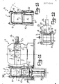
- Figures 11, 12 and 13 show a second example of a die holding device according to the invention, generally indicated at 6, which is located laterally of the horizontal extrusion axis press 1 close to the extrusion working position.
- this second example of the device 6 according to the invention those component parts which are constructionally or functionally the equivalent of the component parts described in connection with the die exchange device shown in Figures 1 to 10 will be denoted by the same reference numerals.
- the die exchange device 6 comprises a supporting column 7 provided with four vertically extending guides 8 consisting of parallel cylindrical columns placed at the vertices of a quadrilateral.
- the device 6 comprises a carriage 10 mounted for sliding movement along the guides 8, which carriage is formed with two superimposed rest shelves, respectively an upper one 11 and lower one 12, each adapted to carry a respective die holding slide 4.
- the shelves 11 and 12 are horizontal, spaced apart by a set distance according to the slide 4 size, and are provided with identical guides of those described in connection with the first embodiment of this die exchange device 6.
- Indicated at 20 is a hydraulic cylinder which constitutes drive means operative on the carriage 10, at the lower shelf 12, to drive it vertically along the guides 8 and take each shelf, 11 or 12, alternately to a set position level with the extrusion working position of the press 1.
- the upper shelf 11 is pivoted at one end 11a to one side of the carriage 10, and is, by the action of a small hydraulic cylinder 32 mounted between the end 11a and the carriage 10, made tiltable through an angle of at least 90°.
- the die exchange device 6 further comprises pusher means 25 mounted on the press 1 to shift a die holding slide 4 from a shelf, 11 or 12, located at the above-noted set position to the extrusion working position, and vice versa.
- the pusher means 15 are comprised of a hydraulic cylinder 26 operative on a movable body 27 having a hole 31 and being adapted to engage with a slide 4 via coupling means 28.
- the above-noted coupling means 28 are comprised of a hammerhead-shaped lug 29 extending in a vertical direction and formed on the body 27, and of a mating grooved seat 30 open both at the bottom and at the top which is formed in each die holding slide 4.
- a die 3 is exchanged by means of the second embodiment of the die exchange device 6 according to the invention in a similar manner to that previously described by operating the pusher means 25 and driving the carriage 10 by the drive means 20 in a vertical direction.
- a tiltable upper shelf is specially advantageous in that it makes a die contained in the slide located on the lower shelf of the carriage in the die exchange device of this invention accessible from above.
Landscapes
- Engineering & Computer Science (AREA)
- Mechanical Engineering (AREA)
- Extrusion Of Metal (AREA)
Applications Claiming Priority (2)
| Application Number | Priority Date | Filing Date | Title |
|---|---|---|---|
| IT19021/87A IT1201111B (it) | 1987-01-08 | 1987-01-08 | Dispositivo di cambio matrici per presse ad estrusione di tipo orizzontale |
| IT1902187 | 1987-01-08 |
Publications (1)
| Publication Number | Publication Date |
|---|---|
| EP0274366A1 true EP0274366A1 (en) | 1988-07-13 |
Family
ID=11153908
Family Applications (1)
| Application Number | Title | Priority Date | Filing Date |
|---|---|---|---|
| EP87830469A Withdrawn EP0274366A1 (en) | 1987-01-08 | 1987-12-29 | A die exchange device for horizontal axis extruding presses |
Country Status (3)
| Country | Link |
|---|---|
| US (1) | US4856314A (it) |
| EP (1) | EP0274366A1 (it) |
| IT (1) | IT1201111B (it) |
Cited By (3)
| Publication number | Priority date | Publication date | Assignee | Title |
|---|---|---|---|---|
| FR2664835A1 (fr) * | 1990-07-19 | 1992-01-24 | Clecim Sa | Presse a filer. |
| CN103128118A (zh) * | 2013-01-24 | 2013-06-05 | 中国重型机械研究院股份公司 | 双动正反向挤压机用新型模具快换装置及其快换方法 |
| US9346210B2 (en) | 2011-12-02 | 2016-05-24 | Exco Technologies Limited | Extrusion die pre-heating system, apparatus and method |
Families Citing this family (3)
| Publication number | Priority date | Publication date | Assignee | Title |
|---|---|---|---|---|
| DE4128677C2 (de) * | 1991-08-29 | 1994-07-21 | Hasenclever Maschf Sms | Liegende Metallstrangpresse |
| US7044704B1 (en) * | 2003-03-03 | 2006-05-16 | Roose Manufacturing Co. | Portable load lifting bed |
| IT201800020815A1 (it) * | 2018-12-21 | 2020-06-21 | Danieli Off Mecc | Pressa per lestrusione diretta di materiale metallico |
Citations (3)
| Publication number | Priority date | Publication date | Assignee | Title |
|---|---|---|---|---|
| FR2288611A1 (fr) * | 1974-10-22 | 1976-05-21 | Secim | Dispositif de changement de porte-filiere |
| GB1454839A (en) * | 1973-05-25 | 1976-11-03 | Wean United Inc | Extrusion press |
| DD157174A1 (de) * | 1981-03-13 | 1982-10-20 | Helmut Drexler | Werkzeugwechseleinrichtung |
Family Cites Families (6)
| Publication number | Priority date | Publication date | Assignee | Title |
|---|---|---|---|---|
| DE1152084B (de) * | 1958-12-24 | 1963-08-01 | Hydraulik Gmbh | Vorrichtung zum Matrizenwechsel an Metallstrangpressen |
| GB897040A (en) * | 1959-06-26 | 1962-05-23 | Hydraulik Gmbh | An extrusion press having a die changing device |
| GB1165619A (en) * | 1967-05-04 | 1969-10-01 | Davy & United Eng Co Ltd | Extrusion Press. |
| US4402208A (en) * | 1981-04-13 | 1983-09-06 | Sutton Enigneering Company | Indirect extrusion press with die changer |
| JPS60106618A (ja) * | 1983-11-14 | 1985-06-12 | Ube Ind Ltd | 押出プレスのダイス交換装置 |
| JPS60199518A (ja) * | 1984-03-26 | 1985-10-09 | Ube Ind Ltd | 押出プレスのダイス交換装置 |
-
1987
- 1987-01-08 IT IT19021/87A patent/IT1201111B/it active
- 1987-12-29 EP EP87830469A patent/EP0274366A1/en not_active Withdrawn
-
1988
- 1988-01-07 US US07/141,522 patent/US4856314A/en not_active Expired - Lifetime
Patent Citations (3)
| Publication number | Priority date | Publication date | Assignee | Title |
|---|---|---|---|---|
| GB1454839A (en) * | 1973-05-25 | 1976-11-03 | Wean United Inc | Extrusion press |
| FR2288611A1 (fr) * | 1974-10-22 | 1976-05-21 | Secim | Dispositif de changement de porte-filiere |
| DD157174A1 (de) * | 1981-03-13 | 1982-10-20 | Helmut Drexler | Werkzeugwechseleinrichtung |
Cited By (4)
| Publication number | Priority date | Publication date | Assignee | Title |
|---|---|---|---|---|
| FR2664835A1 (fr) * | 1990-07-19 | 1992-01-24 | Clecim Sa | Presse a filer. |
| US9346210B2 (en) | 2011-12-02 | 2016-05-24 | Exco Technologies Limited | Extrusion die pre-heating system, apparatus and method |
| CN103128118A (zh) * | 2013-01-24 | 2013-06-05 | 中国重型机械研究院股份公司 | 双动正反向挤压机用新型模具快换装置及其快换方法 |
| CN103128118B (zh) * | 2013-01-24 | 2016-03-16 | 中国重型机械研究院股份公司 | 双动正反向挤压机用新型模具快换装置及其快换方法 |
Also Published As
| Publication number | Publication date |
|---|---|
| IT1201111B (it) | 1989-01-27 |
| US4856314A (en) | 1989-08-15 |
| IT8719021A0 (it) | 1987-01-08 |
Similar Documents
| Publication | Publication Date | Title |
|---|---|---|
| EP0274366A1 (en) | A die exchange device for horizontal axis extruding presses | |
| CN109534937B (zh) | 一种火药柱的压制装置及其压制火药柱的方法 | |
| US4342212A (en) | Indirect extrusion press | |
| CN112404242B (zh) | 一种长型管件冲孔设备 | |
| US5023037A (en) | Method of and arrangement for manufacturing enclosed blocks | |
| US4926539A (en) | Apparatus having a lifting frame for processing workpieces | |
| AU641922B2 (en) | Removable slide presses | |
| US5915515A (en) | Die lifting mechanism | |
| JPS6144578B2 (it) | ||
| CN217837439U (zh) | 管件自动上下料加工设备 | |
| CN117399887A (zh) | 一种集装箱生产焊接用固定工装 | |
| US3228226A (en) | Multi-container extrusion press | |
| WO1984000739A1 (fr) | Installation d'emmagasinage et de mise a disposition pour pieces allongees | |
| US3427857A (en) | Method and apparatus for operating the ram of an impact machine | |
| US3323347A (en) | Hydraulic press of the pull-down type | |
| RU2056025C1 (ru) | Устройство для загрузки и выдачи заготовок из печи | |
| JP2000288610A (ja) | インナースタンド式圧延機 | |
| CN119839217B (zh) | 一种具有自动清理功能的连续性锻造装置 | |
| CN220295708U (zh) | 一种矫平机出料装置 | |
| CN111438238B (zh) | 一种钢制汽车车轮平衡块的自动弯曲设备 | |
| EP0299927A2 (en) | Apparatus for cutting single and double glass sheets | |
| US3427701A (en) | Apparatus for assembling gratings | |
| JPH0260408B2 (it) | ||
| DE2147367A1 (de) | Plasmalichtbogenofen | |
| CN113086471B (zh) | 用于型材的立体储存设备 |
Legal Events
| Date | Code | Title | Description |
|---|---|---|---|
| PUAI | Public reference made under article 153(3) epc to a published international application that has entered the european phase |
Free format text: ORIGINAL CODE: 0009012 |
|
| AK | Designated contracting states |
Kind code of ref document: A1 Designated state(s): AT BE CH DE ES FR GB GR LI LU NL SE |
|
| 17P | Request for examination filed |
Effective date: 19880709 |
|
| 17Q | First examination report despatched |
Effective date: 19900117 |
|
| STAA | Information on the status of an ep patent application or granted ep patent |
Free format text: STATUS: THE APPLICATION IS DEEMED TO BE WITHDRAWN |
|
| 18D | Application deemed to be withdrawn |
Effective date: 19900728 |