EP0277585A2 - Filière pour la fabrication de fibres - Google Patents
Filière pour la fabrication de fibres Download PDFInfo
- Publication number
- EP0277585A2 EP0277585A2 EP88101135A EP88101135A EP0277585A2 EP 0277585 A2 EP0277585 A2 EP 0277585A2 EP 88101135 A EP88101135 A EP 88101135A EP 88101135 A EP88101135 A EP 88101135A EP 0277585 A2 EP0277585 A2 EP 0277585A2
- Authority
- EP
- European Patent Office
- Prior art keywords
- bushing
- plate
- thermocouple
- tube
- rod
- Prior art date
- Legal status (The legal status is an assumption and is not a legal conclusion. Google has not performed a legal analysis and makes no representation as to the accuracy of the status listed.)
- Withdrawn
Links
- 239000000835 fiber Substances 0.000 title description 4
- 238000000034 method Methods 0.000 claims abstract description 6
- 239000006060 molten glass Substances 0.000 claims description 13
- 239000010970 precious metal Substances 0.000 claims description 6
- 239000003365 glass fiber Substances 0.000 claims description 5
- 238000003466 welding Methods 0.000 claims description 3
- 229910052751 metal Inorganic materials 0.000 claims description 2
- 239000002184 metal Substances 0.000 claims description 2
- 229910000923 precious metal alloy Inorganic materials 0.000 claims description 2
- 238000002844 melting Methods 0.000 claims 1
- 230000008018 melting Effects 0.000 claims 1
- 239000011152 fibreglass Substances 0.000 abstract description 3
- BASFCYQUMIYNBI-UHFFFAOYSA-N platinum Chemical compound [Pt] BASFCYQUMIYNBI-UHFFFAOYSA-N 0.000 description 10
- 238000005259 measurement Methods 0.000 description 8
- 239000011521 glass Substances 0.000 description 5
- 229910052697 platinum Inorganic materials 0.000 description 5
- 229910000629 Rh alloy Inorganic materials 0.000 description 3
- PXXKQOPKNFECSZ-UHFFFAOYSA-N platinum rhodium Chemical compound [Rh].[Pt] PXXKQOPKNFECSZ-UHFFFAOYSA-N 0.000 description 3
- 229910052703 rhodium Inorganic materials 0.000 description 3
- 239000010948 rhodium Substances 0.000 description 3
- MHOVAHRLVXNVSD-UHFFFAOYSA-N rhodium atom Chemical compound [Rh] MHOVAHRLVXNVSD-UHFFFAOYSA-N 0.000 description 3
- KDLHZDBZIXYQEI-UHFFFAOYSA-N Palladium Chemical compound [Pd] KDLHZDBZIXYQEI-UHFFFAOYSA-N 0.000 description 2
- MCMNRKCIXSYSNV-UHFFFAOYSA-N Zirconium dioxide Chemical compound O=[Zr]=O MCMNRKCIXSYSNV-UHFFFAOYSA-N 0.000 description 2
- 238000004873 anchoring Methods 0.000 description 2
- 239000000919 ceramic Substances 0.000 description 2
- 238000004519 manufacturing process Methods 0.000 description 2
- 239000000463 material Substances 0.000 description 2
- 238000004804 winding Methods 0.000 description 2
- KJTLSVCANCCWHF-UHFFFAOYSA-N Ruthenium Chemical compound [Ru] KJTLSVCANCCWHF-UHFFFAOYSA-N 0.000 description 1
- 229910045601 alloy Inorganic materials 0.000 description 1
- 239000000956 alloy Substances 0.000 description 1
- 230000015572 biosynthetic process Effects 0.000 description 1
- 229910010293 ceramic material Inorganic materials 0.000 description 1
- 238000010276 construction Methods 0.000 description 1
- 239000004035 construction material Substances 0.000 description 1
- 230000003247 decreasing effect Effects 0.000 description 1
- 238000010292 electrical insulation Methods 0.000 description 1
- 238000007496 glass forming Methods 0.000 description 1
- 230000007774 longterm Effects 0.000 description 1
- 238000012423 maintenance Methods 0.000 description 1
- 239000000155 melt Substances 0.000 description 1
- 229910052763 palladium Inorganic materials 0.000 description 1
- 230000006903 response to temperature Effects 0.000 description 1
- 229910052707 ruthenium Inorganic materials 0.000 description 1
Images
Classifications
-
- G—PHYSICS
- G01—MEASURING; TESTING
- G01K—MEASURING TEMPERATURE; MEASURING QUANTITY OF HEAT; THERMALLY-SENSITIVE ELEMENTS NOT OTHERWISE PROVIDED FOR
- G01K1/00—Details of thermometers not specially adapted for particular types of thermometer
- G01K1/14—Supports; Fastening devices; Arrangements for mounting thermometers in particular locations
-
- C—CHEMISTRY; METALLURGY
- C03—GLASS; MINERAL OR SLAG WOOL
- C03B—MANUFACTURE, SHAPING, OR SUPPLEMENTARY PROCESSES
- C03B37/00—Manufacture or treatment of flakes, fibres, or filaments from softened glass, minerals, or slags
- C03B37/07—Controlling or regulating
Definitions
- the present invention relates to a fiber forming bushing. More particularly, the present invention relates to a glass fiber forming bushing having a novel electrical measuring system. Still more particularly, the present invention relates to a fiber glass forming bushing and associated thermocouples for use in recording temperatures from the bottom of the bushing.
- Fiber glass is currently produced from glass fiber bushings which typically are controlled electrically to maintain the temperature of the glass contained in the bushing within a desired range. Maintenance of a desired glass temperature insures uniform viscosity of the molten glass in a bushing and thus uniform filament formation as fibers are drawn from the molten glass as it exits through the bushing orifices, all other conditions being equal.
- the bushings themselves are precious metal containers typically having 4 sides and a bottom and are generally open at the top.
- the bushings are provided with a plurality of orifices in the bottom which normally have tips depending therefrom through which the molten glass contained in the bushing flows to form the glass fibers.
- Bushings are heated by applying current to leads located at each end of the bushing, the leads being connected to the secondary winding of a suitably sized power transformer.
- the current is increased or decreased by connecting a power pack to the power transformer and altering the output of the power pack by feeding signals to it from a controller that is fed signals from thermocouples attached to the bushing that monitor its operating temperatures continuously.
- thermocouple junction attached to the bottom or tip plate of the bushing be protected and be as flat as possible with respect to the tip plate of the bushing to which it is attached.
- Molten glass movement in the bushing caused by the molten glass flowing from the forehearth to the bushing and glass currents contained within the bushing itself should not be capable of disturbing the electrical connection of the thermocouple junction and wires with the bushing tip plate.
- the junction should be able to be welded to the bushing tip plate with a minimum of difficulty.
- the applicants have provided a bushing and thermocouple arrangement that is simple in construction, easy to assemble and which provides for accurate and reliable long-term measurements of the bushing tip plate temperature.
- the bushing and thermocouple arrangement utilized provides for a tubular sheath surrounding the thermocouple wires utilized to make measurements of a bushing tip plate.
- a plate is provided at one end of the tubular member in which both thermocouple wires and the thermocouple wire junction itself are embedded.
- An anchoring means is located on the undersurface of the tip plate and adapted to mate with an opening in the bushing bottom. Prior to assembly, the anchoring means which has a rod-like member depending downwardly from it is inserted in an opening in the tip plate of the bushing.
- This rod is firmly welded to the underside of the plate so that it can be pulled downward with sufficient force to ensure that the plate itself at the end of the sheath lies flat against the bottom of the bushing.
- the rod is then cut below the opening and the remainder of it is welded into the bushing opening where its mass melts and forms a part of the bushing bottom.
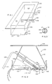
- FIG. 1 there is shown therein a rectangular shaped bushing generally indicated at 100 having sidewalls 102, 113, 115 and 114 and a bottom or tip plate 101.
- bottom 101 does not show any orifices for the exit of molten glass, but it will be understood by the skilled artisan that bottom 101 in a production bushing would contain a plurality of orifices typically arranged in rows.
- thermocouple junctions 107 and 110 Located in the sidewall 102 of the bushing shown are thermocouple junctions 107 and 110.
- Thermocouple junction 107 is formed from thermocouple wires 108 and 109.
- Thermocouple junction 110 is formed from thermocouple wires 111 and 112.
- thermocouple junction 104 which is formed from thermocouple wires 105 and 106.
- Thermocouple wires 105 and 106 are contained in a housing 150 which is identical to the tube 150, shown more clearly in Figure 2, and in a cross-section thereof shown in Figure 3.
- housing 150 is a metal chamber in which thermocouple wires 105 and 106 are carried and the thermocouple wires 105 and 106 are surrounded in that chamber by a ceramic electrical insulation, material 151.
- the ceramic material is a material such as Fiberfrax or a cast ceramic.
- the bushing 100 is provided with a bushing flange 103 which is normally utilized in operation to bolt or affix the bushing to a bushing block located above it and through which molten glass flows from a glass fiber forming forehearth to the bushing proper.
- This flow of molten glass provides a constant supply of molten glass to the bushing so that fibers may be continuously drawn therefrom.
- walls 113 and 114 are normally provided with electrical connections so that the bushing 100 can be connected to a suitable power supply such as the secondary winding of an AC power transformer for delivering electrical energy to the bushing during its operation thereby providing sufficient heat to the bushing to maintain the glass contained therein in the molten condition.
- thermocouples and thermocouple tubes are metallic in structure and are constructed of precious metals or precious metal alloys.
- the thermocouples are constructed of platinum and rhodium wires which are joined at one end to provide a thermocouple junction. The other ends of the wires are used to provide electronic signals in response to temperatures sensed by the thermocouple junction.
- the bushing construction materials are typically platinum and platinum-rhodium alloys. Typical alloys are platinum-rhodium alloys comprising 90% platinum and 10% rhodium and more preferably 80% platinum and 20% rhodium. It is within the contemplation of the invention to also utilize grain stabilized precious metals such as zirconia stabilized platinum and platinum-rhodium alloys. In some instances, other precious metals such as ruthenium and palladium may be used.
- a bushing similar to that shown in Figure 1 is shown in an end view in Figure 2.
- the major distinction between the bushing shown therein and the bushing of Figure 1 is that the sidewalls 102 and 115 are sloped from the bottom 101 to the top flange 103 and the bushing is divided lengthwise into two halves.
- the tube 150 is shown exiting through opening 153 in wall 102 of the bushing and thermocouple wires 105 and 106 are suitably connected to a control apparatus not shown in the drawing.
- a plate 104a At the base of the tube 150 is a plate 104a in which the thermocouple junction 104 is embedded.
- the bushing bottom 101 is provided with a hole 157 into which is inserted a rod member 156 having at its end a weld point 155.
- the rod 156 is utilized to pull the plate member 104a snugly against the bottom 101 of the bushing during fabrication so that the plate 104a is firmly attached to the bottom prior to welding it in place.
- rod 156 is cut below hole 157 and the portion of the rod in the hole 157 is melted to fill the hole 157. That portion of the rod 156 which is melted into the bushing bottom becomes a part of the bushing bottom.
- thermocouple weldment described in and shown in Figure 2 provides a junction at the bottom of a bushing tip plate in the interior thereof which permits easy access for attachment, protects the thermocouple junction of the thermocouple wires 105 and 106 so that glass does not contaminate the wires or move them in any way during operation and the plate member 104a has completely encased the thermocouple junction 104 thereby providing a method of obtaining a true reading of the bushing bottom without any opportunity for the molten glass contained in the bushing to disturb the thermocouple junction 104 from its attachment to the bottom 101.
- Figure 2 depicts a split bushing, i.e., a bushing which contains two separate segments separated by the corrugation 160 shown, the left hand and right hand segments shown each containing rows of bushing tips 118. While only two tips are shown in each segment, the skilled artisan will recognize that the size and number of orifice tips will depend on the product being made and are matters well recognized by the skilled art.
Landscapes
- Engineering & Computer Science (AREA)
- Chemical & Material Sciences (AREA)
- Physics & Mathematics (AREA)
- General Physics & Mathematics (AREA)
- Life Sciences & Earth Sciences (AREA)
- General Life Sciences & Earth Sciences (AREA)
- Geochemistry & Mineralogy (AREA)
- Manufacturing & Machinery (AREA)
- Materials Engineering (AREA)
- Organic Chemistry (AREA)
- Manufacture, Treatment Of Glass Fibers (AREA)
- Measuring Temperature Or Quantity Of Heat (AREA)
Applications Claiming Priority (2)
| Application Number | Priority Date | Filing Date | Title |
|---|---|---|---|
| US07/013,473 US4746344A (en) | 1987-02-02 | 1987-02-02 | Fiber forming bushing and method for providing |
| US13473 | 1987-02-02 |
Publications (2)
| Publication Number | Publication Date |
|---|---|
| EP0277585A2 true EP0277585A2 (fr) | 1988-08-10 |
| EP0277585A3 EP0277585A3 (fr) | 1990-01-03 |
Family
ID=21760141
Family Applications (1)
| Application Number | Title | Priority Date | Filing Date |
|---|---|---|---|
| EP88101135A Withdrawn EP0277585A3 (fr) | 1987-02-02 | 1988-01-27 | Filière pour la fabrication de fibres |
Country Status (4)
| Country | Link |
|---|---|
| US (1) | US4746344A (fr) |
| EP (1) | EP0277585A3 (fr) |
| JP (1) | JPH0643252B2 (fr) |
| CA (1) | CA1311358C (fr) |
Cited By (2)
| Publication number | Priority date | Publication date | Assignee | Title |
|---|---|---|---|---|
| US6408651B1 (en) | 1999-12-30 | 2002-06-25 | Corning Incorporated | Method of manufacturing optical fibers using thermopiles to measure fiber energy |
| CN102351416A (zh) * | 2011-08-25 | 2012-02-15 | 巨石集团有限公司 | 一种漏板应急系统、dcs系统及漏板应急方法 |
Families Citing this family (4)
| Publication number | Priority date | Publication date | Assignee | Title |
|---|---|---|---|---|
| US4794625A (en) * | 1988-01-28 | 1988-12-27 | Ppg Industries, Inc. | Method and apparatus for contolling temperature in a fiber glass forming bushing |
| US5140732A (en) * | 1991-06-13 | 1992-08-25 | Manville Corporation | Method of forming bushing plate for glass filaments |
| DE69509249T2 (de) * | 1994-10-12 | 1999-12-30 | Advanced Glassfiber Yarns Llc, Aiken | Verfahren und vorrichtung zum regeln der heizung und kühlung in segmenten einer glasfaserspinndüse |
| US6070437A (en) * | 1998-11-12 | 2000-06-06 | Owens Corning Fiberglas Technology, Inc. | Tip-plate thermocouple |
Family Cites Families (7)
| Publication number | Priority date | Publication date | Assignee | Title |
|---|---|---|---|---|
| US3649231A (en) * | 1968-09-18 | 1972-03-14 | Owens Corning Fiberglass Corp | Method and apparatus for producing fibers with environmental control |
| US4285712A (en) * | 1979-10-22 | 1981-08-25 | Owens-Corning Fiberglass Corporation | Apparatus and method for the production of glass fibers |
| FR2492096A1 (fr) * | 1980-10-14 | 1982-04-16 | Saint Gobain Emballage | Canne pyrometrique |
| US4392879A (en) * | 1981-09-23 | 1983-07-12 | Owens-Corning Fiberglas Corporation | Method of forming glass fibers while monitoring a process condition in a spinner |
| US4546485A (en) * | 1983-12-01 | 1985-10-08 | Ppg Industries, Inc. | Method and apparatus for producing uniform strands from a split fiber glass bushing |
| US4594087A (en) * | 1985-04-01 | 1986-06-10 | Ppg Industries, Inc. | Three-terminal controller for fiber glass bushing |
| US4738700A (en) * | 1986-12-12 | 1988-04-19 | Ppg Industries, Inc. | Method and apparatus for controlling temperature in a fiber glass forming bushing |
-
1987
- 1987-02-02 US US07/013,473 patent/US4746344A/en not_active Expired - Lifetime
-
1988
- 1988-01-20 CA CA000556948A patent/CA1311358C/fr not_active Expired - Lifetime
- 1988-01-27 EP EP88101135A patent/EP0277585A3/fr not_active Withdrawn
- 1988-02-01 JP JP63022661A patent/JPH0643252B2/ja not_active Expired - Lifetime
Cited By (3)
| Publication number | Priority date | Publication date | Assignee | Title |
|---|---|---|---|---|
| US6408651B1 (en) | 1999-12-30 | 2002-06-25 | Corning Incorporated | Method of manufacturing optical fibers using thermopiles to measure fiber energy |
| CN102351416A (zh) * | 2011-08-25 | 2012-02-15 | 巨石集团有限公司 | 一种漏板应急系统、dcs系统及漏板应急方法 |
| CN102351416B (zh) * | 2011-08-25 | 2013-08-14 | 巨石集团有限公司 | 一种漏板应急系统、dcs系统及漏板应急方法 |
Also Published As
| Publication number | Publication date |
|---|---|
| US4746344A (en) | 1988-05-24 |
| EP0277585A3 (fr) | 1990-01-03 |
| JPH0643252B2 (ja) | 1994-06-08 |
| JPS63195145A (ja) | 1988-08-12 |
| CA1311358C (fr) | 1992-12-15 |
Similar Documents
| Publication | Publication Date | Title |
|---|---|---|
| US6070437A (en) | Tip-plate thermocouple | |
| US4746344A (en) | Fiber forming bushing and method for providing | |
| US3573014A (en) | Apparatus and process for extruding glass fibers | |
| EP1362011B1 (fr) | Dispositifs de distribution de verre fondu et procede d'utilisation de tels dispositifs | |
| US4344785A (en) | Modular molten glass column | |
| US4285712A (en) | Apparatus and method for the production of glass fibers | |
| EP0275410B1 (fr) | Méthode et appareil pour contrôler la température d'un élement de chauffage de chaleur joule utilisant des signaux de thermocouples | |
| US4957525A (en) | Composite bushing design | |
| CA1237460A (fr) | Avant-creuset chauffe a l'electricite, et methode de regulation de la temperature du verre en fusion qu'il contient | |
| EP0169557B1 (fr) | Filière et son application comme filière de fond dans un avant-corps pour la fabrication de fibres de verre | |
| GB2204732A (en) | Sensor for the measurement of temperature in metal or alloy melts | |
| US4525188A (en) | Fiber forming bushing and method for using same | |
| US4162152A (en) | Molten glass metering device for making lamp bases | |
| MXPA01004142A (en) | Tip-plate thermocouple | |
| JPH0531570A (ja) | 制御下に固化される鋳物の製造法 | |
| JPS596827B2 (ja) | 再溶融式ガラス繊維製造用白金系紡糸炉 | |
| CA1293615C (fr) | Tete de filiere pour fibres de verre creuses | |
| JPH04285091A (ja) | 酸化物単結晶の製造装置 | |
| US4591371A (en) | Glass fiber forming bushing construction | |
| KR810000976B1 (ko) | 글라스파이버 인출 부싱에 사용되는 열전대의 보정 유지 장치 | |
| CA1203827A (fr) | Regulateur de chauffage electrique dans l'avant-creuset d'un four a verre | |
| JPS6228626A (ja) | 溶融金属連続測温計 | |
| CA1121601A (fr) | Filiere de faconnage de fibres | |
| WO1982002888A1 (fr) | Dispositif et procede de production de fibres de verre | |
| JPH06331419A (ja) | ガラス原料層の厚み測定方法及び測定装置 |
Legal Events
| Date | Code | Title | Description |
|---|---|---|---|
| PUAI | Public reference made under article 153(3) epc to a published international application that has entered the european phase |
Free format text: ORIGINAL CODE: 0009012 |
|
| AK | Designated contracting states |
Kind code of ref document: A2 Designated state(s): BE CH DE FR GB IT LI NL |
|
| PUAL | Search report despatched |
Free format text: ORIGINAL CODE: 0009013 |
|
| AK | Designated contracting states |
Kind code of ref document: A3 Designated state(s): BE CH DE FR GB IT LI NL |
|
| STAA | Information on the status of an ep patent application or granted ep patent |
Free format text: STATUS: THE APPLICATION HAS BEEN WITHDRAWN |
|
| 18W | Application withdrawn |
Withdrawal date: 19900411 |
|
| PGFP | Annual fee paid to national office [announced via postgrant information from national office to epo] |
Ref country code: LU Payment date: 19930121 Year of fee payment: 7 |