EP0284317B1 - Tuyau en couches de béton et méthode pour sa fabrication - Google Patents
Tuyau en couches de béton et méthode pour sa fabrication Download PDFInfo
- Publication number
- EP0284317B1 EP0284317B1 EP88302435A EP88302435A EP0284317B1 EP 0284317 B1 EP0284317 B1 EP 0284317B1 EP 88302435 A EP88302435 A EP 88302435A EP 88302435 A EP88302435 A EP 88302435A EP 0284317 B1 EP0284317 B1 EP 0284317B1
- Authority
- EP
- European Patent Office
- Prior art keywords
- concrete
- layer
- resin
- type composite
- composite pipe
- Prior art date
- Legal status (The legal status is an assumption and is not a legal conclusion. Google has not performed a legal analysis and makes no representation as to the accuracy of the status listed.)
- Expired - Lifetime
Links
- 239000002131 composite material Substances 0.000 title claims description 27
- 238000000034 method Methods 0.000 title claims description 14
- 239000010410 layer Substances 0.000 claims description 86
- 239000004567 concrete Substances 0.000 claims description 74
- 239000011347 resin Substances 0.000 claims description 42
- 229920005989 resin Polymers 0.000 claims description 42
- 238000005260 corrosion Methods 0.000 claims description 38
- 230000007797 corrosion Effects 0.000 claims description 38
- 239000011241 protective layer Substances 0.000 claims description 38
- 239000000203 mixture Substances 0.000 claims description 11
- XLYOFNOQVPJJNP-UHFFFAOYSA-N water Substances O XLYOFNOQVPJJNP-UHFFFAOYSA-N 0.000 claims description 10
- 230000001133 acceleration Effects 0.000 claims description 8
- 239000004848 polyfunctional curative Substances 0.000 claims description 7
- 238000005266 casting Methods 0.000 claims description 5
- 239000000126 substance Substances 0.000 description 7
- 238000002347 injection Methods 0.000 description 5
- 239000007924 injection Substances 0.000 description 5
- VYPSYNLAJGMNEJ-UHFFFAOYSA-N Silicium dioxide Chemical compound O=[Si]=O VYPSYNLAJGMNEJ-UHFFFAOYSA-N 0.000 description 4
- 230000008602 contraction Effects 0.000 description 4
- 239000003822 epoxy resin Substances 0.000 description 4
- 229920000647 polyepoxide Polymers 0.000 description 4
- 230000000694 effects Effects 0.000 description 3
- KUBDPQJOLOUJRM-UHFFFAOYSA-N 2-(chloromethyl)oxirane;4-[2-(4-hydroxyphenyl)propan-2-yl]phenol Chemical compound ClCC1CO1.C=1C=C(O)C=CC=1C(C)(C)C1=CC=C(O)C=C1 KUBDPQJOLOUJRM-UHFFFAOYSA-N 0.000 description 2
- VTYYLEPIZMXCLO-UHFFFAOYSA-L Calcium carbonate Chemical compound [Ca+2].[O-]C([O-])=O VTYYLEPIZMXCLO-UHFFFAOYSA-L 0.000 description 2
- 125000001931 aliphatic group Chemical group 0.000 description 2
- 150000001412 amines Chemical class 0.000 description 2
- IISBACLAFKSPIT-UHFFFAOYSA-N bisphenol A Chemical group C=1C=C(O)C=CC=1C(C)(C)C1=CC=C(O)C=C1 IISBACLAFKSPIT-UHFFFAOYSA-N 0.000 description 2
- 239000004568 cement Substances 0.000 description 2
- 238000004898 kneading Methods 0.000 description 2
- 238000004519 manufacturing process Methods 0.000 description 2
- 238000000465 moulding Methods 0.000 description 2
- 229920000768 polyamine Polymers 0.000 description 2
- 239000004576 sand Substances 0.000 description 2
- 239000004593 Epoxy Substances 0.000 description 1
- 239000004952 Polyamide Substances 0.000 description 1
- 230000015572 biosynthetic process Effects 0.000 description 1
- 229910000019 calcium carbonate Inorganic materials 0.000 description 1
- 239000011362 coarse particle Substances 0.000 description 1
- 238000001035 drying Methods 0.000 description 1
- 239000000839 emulsion Substances 0.000 description 1
- 230000001747 exhibiting effect Effects 0.000 description 1
- 239000000945 filler Substances 0.000 description 1
- 239000010419 fine particle Substances 0.000 description 1
- 239000007788 liquid Substances 0.000 description 1
- 239000000463 material Substances 0.000 description 1
- 229920002647 polyamide Polymers 0.000 description 1
- 239000002244 precipitate Substances 0.000 description 1
- 238000010298 pulverizing process Methods 0.000 description 1
- 239000000377 silicon dioxide Substances 0.000 description 1
- 238000003892 spreading Methods 0.000 description 1
Images


Classifications
-
- B—PERFORMING OPERATIONS; TRANSPORTING
- B28—WORKING CEMENT, CLAY, OR STONE
- B28B—SHAPING CLAY OR OTHER CERAMIC COMPOSITIONS; SHAPING SLAG; SHAPING MIXTURES CONTAINING CEMENTITIOUS MATERIAL, e.g. PLASTER
- B28B21/00—Methods or machines specially adapted for the production of tubular articles
- B28B21/02—Methods or machines specially adapted for the production of tubular articles by casting into moulds
- B28B21/10—Methods or machines specially adapted for the production of tubular articles by casting into moulds using compacting means
- B28B21/22—Methods or machines specially adapted for the production of tubular articles by casting into moulds using compacting means using rotatable mould or core parts
- B28B21/30—Centrifugal moulding
-
- B—PERFORMING OPERATIONS; TRANSPORTING
- B28—WORKING CEMENT, CLAY, OR STONE
- B28B—SHAPING CLAY OR OTHER CERAMIC COMPOSITIONS; SHAPING SLAG; SHAPING MIXTURES CONTAINING CEMENTITIOUS MATERIAL, e.g. PLASTER
- B28B21/00—Methods or machines specially adapted for the production of tubular articles
- B28B21/92—Methods or apparatus for treating or reshaping
- B28B21/94—Methods or apparatus for treating or reshaping for impregnating or coating by applying liquids or semi-liquids
-
- F—MECHANICAL ENGINEERING; LIGHTING; HEATING; WEAPONS; BLASTING
- F16—ENGINEERING ELEMENTS AND UNITS; GENERAL MEASURES FOR PRODUCING AND MAINTAINING EFFECTIVE FUNCTIONING OF MACHINES OR INSTALLATIONS; THERMAL INSULATION IN GENERAL
- F16L—PIPES; JOINTS OR FITTINGS FOR PIPES; SUPPORTS FOR PIPES, CABLES OR PROTECTIVE TUBING; MEANS FOR THERMAL INSULATION IN GENERAL
- F16L9/00—Rigid pipes
- F16L9/08—Rigid pipes of concrete, cement, or asbestos cement, with or without reinforcement
-
- Y—GENERAL TAGGING OF NEW TECHNOLOGICAL DEVELOPMENTS; GENERAL TAGGING OF CROSS-SECTIONAL TECHNOLOGIES SPANNING OVER SEVERAL SECTIONS OF THE IPC; TECHNICAL SUBJECTS COVERED BY FORMER USPC CROSS-REFERENCE ART COLLECTIONS [XRACs] AND DIGESTS
- Y10—TECHNICAL SUBJECTS COVERED BY FORMER USPC
- Y10S—TECHNICAL SUBJECTS COVERED BY FORMER USPC CROSS-REFERENCE ART COLLECTIONS [XRACs] AND DIGESTS
- Y10S138/00—Pipes and tubular conduits
- Y10S138/06—Corrosion
Definitions
- the present invention relates to a concrete-type composite pipe having large rigidity and strength as well as resistance against chemicals, and to a method of producing the same.
- a concrete-type composite pipe in which a corrosion protective layer of a tar-epoxy resin or of a mixture of epoxy resin and aggregate is formed on the inner surface or on the outer surface, or on both the inner and outer surfaces of the steam-cured concrete layer utilizing a conventional cheaply constructed concrete-type pipe that has large rigidity.
- the corrosion protective layer peels off at the boundary surface relative to the concrete layer. Therefore, the composite pipe could not fully exhibit its function with regard to the strength and resistance against chemicals.
- the corrosion protective layer is formed by pouring into a vessel a mixture obtained by kneading together the resin and the aggregate, carrying the vessel to pour the mixture onto the inner surface of the concrete layer after it is cured with steam, and spreading the mixture in a centrifugal manner, requiring cumbersome operation for kneading the materials and for carrying the resin.
- the mixture lacks flowability, extended periods of time are required before the layer is formed maintaining a uniform thickness.
- a concrete type composite pipe comprising a cylindrical concrete layer; a corrosion protective layer formed of a mixture of resin and aggregates disposed concentrically with respect to said cylindrical concrete layer, and an intermediate layer composed of resin and concrete formed in a boundary region between said cylindrical concrete layer and said corrosion protective layer, said mixed intermediate layer having properties intermediate said concrete layer and said corrosion protective layer.
- Figs. 1 A and 1 B illustrate a concrete-type composite pipe A having a laminate structure in which a corrosion protective layer 2 consisting of a mixture of resin and aggregate (here, the word “aggregate” generally stands for the one that is obtained by pulverizing Chamotte, the one obtained by drying the sand or gravel, or the filler such as silica sand or calcium carbonate, which may be used alone or being blended together) is formed on the inner surface of a concrete layer 1.
- a mixed intermediate layer 4 which is composed of a coarse granular aggregate 3, a resin which partly penetrates the concrete layer 1, and a concrete.
- the mixed intermediate layer 4 composed of the resin and concrete exhibits properties such as coefficient of thermal expansion and coefficient of contraction that lie between those of the concrete layer 1 and the corrosion protective layer 2. Therefore, even when the pipe is subjected to the temperature change or is placed in the step of curing where contraction is inevitable, stress resulting from the difference in temperature stress and contraction by curing between the concrete layer 1 and the corrosion protective layer 2 is reduced with the result that the layers are not peeled off.
- the concrete layer 1 and the corrosion protective layer 2 are strongly and intimately adhered together into a unitary structure via the mixed intermediate layer 4 composed of resin and concrete, and whereby there are maintained large re- gidity inherent in the concrete layer 1 and resistance against chemicals and strength inherent in the corrosion protective layer 2.
- the outer layer was comprised of the concrete layer in the above-mentioned embodiment, it is also possible to realize a concrete-type composite pipe in which the outer layer is comprised of the corrosion protective layer or in which the corrosion protective layer is formed on both the inner and outer surfaces of the concrete layer.
- a side molding frame 5 secured to both ends of a drum mold 6 is placed on a drive roller 7 and a driven rollr 8.
- the driving force of a motor (not shown) is transmitted to the drive roller 7 to rotate said drum mold 6 such that an acceleration of centrifugal force of normally 3 to 5 g or at most up to 15 g is obtained at an inner periphery thereof.
- the radially inner portion of the concrete layer 1 is comprised of a relatively large amount of cement and fine aggregates to make the region relatively soft. Since the innermost portion of the layer is composed of water, said drum mold is stopped after the passage of above mentioned time period to discharge said water out of the drum mold.
- the concrete in layer after being subjected to the tightening or physically hardening step but not chemically hardened yet as described above is known as fresh concrete.
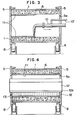
- a step of forming the corrosion protective layer 2 is required to be started before said fresh concrete is chemically hardened. More specifically, an injection pipe 10 is inserted through longitudinally through said drum mold 6 by way of the opening 5a as shown in Fig. 3 normally immediately after the drum mold is stopped. Then, the valve (not shown) is opened to pour down a hydrophilic resion (for example two liquid type water emulsion epoxy resin) mixed with a hardener. At the same time, the drum mold 6 is again stated to rotate to obtain an acceleration of centrifugal force of normally 5 to 20 g in the proximity of the inner surface of the drum mold 6.
- a hydrophilic resion for example two liquid type water emulsion epoxy resin
- the resin having good flowability quickly spreads in inner surface of the concrete layer 1 due to centrifugal force, with the result that the resion layer 11 having a uniform thickness is formed within short periods of time.
- the resin is required to have a hydrophilic property since it comes into contact with the concrete layer 1 that has not been solidified yet.
- hydrophilic resin As a hydrophilic resin to be used in this embodiment, there is bisphenol A type epoxy resin (trade name -EPIKOTE 828 from Yuka Shell Epoxy K.K.) which is to be emulsified with 1 water of 1 to 40 weight percent of the resin. In place thereof, Der 331 from Dow-Chemical Co. or AER 331 of Asahi Ka- sei K.K. may be used after being subjected to the above treatment. In the above cases, water is preferably in a small amount in the above range.
- the hardener includes polyma- mide amine, modified polyamide amine, aliphatic polyamine, modified aliphatic polyamine etc. 30 to 70 parts by weight of any one of the above hardeners is mixed with 100 parts by weight of the hydrophilic resin.
- the injection pipe 10 shown in Fig. 3 has an inner diameter of 2 to 3 centimeters and the hydrophilic resin is discharged under velocity of 0.2 to 0.4 meters per second. Furthermore, a hardener pipe 10' is joined to the injection pipe 10 at a portion 1.2 meters from the outlet. Even if the mixture contains 70 parts by weight of hardener, the pipe 10 will not be blocked because the resin normally takes about 7 minutes to harden.
- the injection pipe 10 is immediately retracted by way of the opening 5a outwardly of the drum mold 6 to be stationed at a separate predetermined place.
- a hopper is introduced thereinto.
- said hopper 12 has about the same longitudinal length as the drum mold 6 and contains aggregate and the like therein. Said aggregates and the like is scattered onto the inner surface of the resin layer 11 by opening a gate 12a in the bottom thereof.
- said hopper 12 is retracted by way of opening 15a outwardly of the drum mold 6 to be stationed at a further predetermined place.
- the motor output is raised to such an extent that an acceleration of centrifugal force of preferably 10 to 15 g and at most 30 to 40 g is obtained.
- the aggregate 13 is uniformly scattered onto the resin layer 11 within a short period of time.
- the drum mold 6 is rotated in this condition for suitable period of time and stopped after the resin hardness.
- the ratio of resin to aggregate can be varied over a very wide range.
- step (iii) In the above-mentioned step (ii), the aggregate 13 floates on the resin layer 11 during the initial stage of scattering. Then, coarse particles in the aggregate 13 precipitate, first, owing to the action of centrifugal force and bite into the concrete layer 1 that has not yet been solidified. Namely, there is formed the mixed intermediate layer 4 consisting of the resin and the concrete and having properties that lie between those of the concrete layer 1 and those of the corrosion protective layer 2 as shown in Figs. 1A and 1B.
- the thickness of the corrosion protective layer 2 should be increased to meet the demand.
- the corrosion protective layer should be centrifugally formed, and the concrete should be thrown onto the inner surface of the corrosion protective layer under the condition where it is not yet hardened to form the layer in a centrifugal manner. It is also possible to form the corrosion protective layer on both the inner and outer surfaces of the concrete layer.
Landscapes
- Engineering & Computer Science (AREA)
- Mechanical Engineering (AREA)
- General Engineering & Computer Science (AREA)
- Manufacturing & Machinery (AREA)
- Chemical & Material Sciences (AREA)
- Ceramic Engineering (AREA)
- Rigid Pipes And Flexible Pipes (AREA)
- Manufacturing Of Tubular Articles Or Embedded Moulded Articles (AREA)
- Laminated Bodies (AREA)
Claims (7)
Applications Claiming Priority (2)
| Application Number | Priority Date | Filing Date | Title |
|---|---|---|---|
| JP62068034A JPH068676B2 (ja) | 1987-03-24 | 1987-03-24 | コンクリ−ト系複合管及びその製造方法 |
| JP68034/87 | 1987-03-24 |
Publications (2)
| Publication Number | Publication Date |
|---|---|
| EP0284317A1 EP0284317A1 (fr) | 1988-09-28 |
| EP0284317B1 true EP0284317B1 (fr) | 1990-06-13 |
Family
ID=13362109
Family Applications (1)
| Application Number | Title | Priority Date | Filing Date |
|---|---|---|---|
| EP88302435A Expired - Lifetime EP0284317B1 (fr) | 1987-03-24 | 1988-03-21 | Tuyau en couches de béton et méthode pour sa fabrication |
Country Status (7)
| Country | Link |
|---|---|
| US (2) | US5035850A (fr) |
| EP (1) | EP0284317B1 (fr) |
| JP (1) | JPH068676B2 (fr) |
| KR (1) | KR920002318B1 (fr) |
| CN (1) | CN1015924B (fr) |
| AU (1) | AU591388B2 (fr) |
| DE (1) | DE3860231D1 (fr) |
Families Citing this family (16)
| Publication number | Priority date | Publication date | Assignee | Title |
|---|---|---|---|---|
| US5037600A (en) * | 1990-04-30 | 1991-08-06 | Amsted Industries Incorporated | Method of applying a polyolefin coating to pipe |
| CA2047787A1 (fr) * | 1991-07-24 | 1993-01-25 | Z. Grant Kafarowski | Dalle decorative en beton |
| US5300391A (en) * | 1991-09-17 | 1994-04-05 | Xerox Corporation | Field assisted processes for preparing imaging members |
| US5874016A (en) * | 1993-10-04 | 1999-02-23 | Sonoco Products Company | Concrete column forming tube having a smooth inside coated surface |
| KR20020039799A (ko) * | 2000-11-22 | 2002-05-30 | 국천표,오의진 | 부식방지용 배수구의 제조방법 |
| US6698451B2 (en) | 2001-02-23 | 2004-03-02 | Schwing America, Inc. | Conveying pipeline mounted inside a boom |
| US6755212B1 (en) | 2001-02-23 | 2004-06-29 | Schwing America, Inc. | Boom stiffening system |
| US6786233B1 (en) | 2001-02-23 | 2004-09-07 | Schwing America, Inc. | Boom utilizing composite material construction |
| US6719009B1 (en) | 2001-02-23 | 2004-04-13 | Schwing America, Inc. | Composite material piping system |
| IL148877A0 (en) * | 2002-03-25 | 2002-09-12 | Steinberg Dov | Molded concrete foundation element and method for its manufacture |
| CN1811251B (zh) * | 2006-02-24 | 2010-05-26 | 衡水长江预应力有限公司 | 小流量斜向应力环保管道及其制备工艺 |
| CN101085536B (zh) * | 2006-06-10 | 2010-06-09 | 上海二十冶金混凝土构件有限公司 | 泵送混凝土浇灌薄壁钢管离心混凝土管桩的方法 |
| EP2225181A1 (fr) * | 2007-11-29 | 2010-09-08 | Corning Incorporated | Réfractaire multicouche résistant au fluage utilisé dans un système de fabrication de verre |
| CN103363203B (zh) * | 2013-08-13 | 2015-06-24 | 王维国 | 内衬玻璃钢混凝土复合管道 |
| DE102016103278A1 (de) * | 2016-02-24 | 2017-08-24 | ACO Severin Ahlmann GmbH & Co Kommanditgesellschaft | Vorrichtung zum Führen von Flüssigkeit und Herstellungsverfahren |
| CN116572384A (zh) * | 2023-06-28 | 2023-08-11 | 湖南三一快而居住宅工业有限公司 | 预制混凝土空心柱的成型装置及预制混凝土空心柱生产线 |
Family Cites Families (20)
| Publication number | Priority date | Publication date | Assignee | Title |
|---|---|---|---|---|
| US1521264A (en) * | 1923-05-08 | 1924-12-30 | Firm Internationale Siegwartba | Method and device for the production of hollow bodies such as pipes, masts, and the like from ferroconcrete |
| US2305017A (en) * | 1940-08-09 | 1942-12-15 | Hume Pipe Company Australia Lt | Manufacture of concrete pipes and like bodies |
| US2675333A (en) * | 1949-12-17 | 1954-04-13 | American Pipe & Constr Co | Pipe apparatus |
| US2624097A (en) * | 1951-01-09 | 1953-01-06 | Norton Co | Method of making dense, hard, abrasion resistant ceramic articles |
| US2774383A (en) * | 1955-06-03 | 1956-12-18 | Insul Fil Co Inc | Insulation for underground conduits and method of producing the same |
| US3177902A (en) * | 1957-12-11 | 1965-04-13 | Rubenstein David | Reinforced pipe and method of making |
| NL246775A (fr) * | 1958-12-27 | |||
| US3150219A (en) * | 1959-08-25 | 1964-09-22 | Schmidt William Karl | Process of making plastic pipes |
| US3341641A (en) * | 1963-10-10 | 1967-09-12 | Allied Chem | Centrifugal casting process |
| US3253075A (en) * | 1963-12-13 | 1966-05-24 | United States Steel Corp | Method of facing concrete pipe |
| US3561493A (en) * | 1965-04-21 | 1971-02-09 | Paul Maillard | Composite tubes and method of manufacturing same |
| AU406528B1 (en) * | 1966-01-27 | 1970-10-08 | Improvements in the manufacture of resin aggregate pipes | |
| US3742985A (en) * | 1967-01-31 | 1973-07-03 | Chemstress Ind Inc | Reinforced pipe |
| FR1577567A (fr) * | 1967-07-07 | 1969-08-08 | ||
| US3532132A (en) * | 1968-01-02 | 1970-10-06 | Chem Stress Ind Inc | Apparatus for the manufacture of reinforced composite concrete pipe-lines |
| US3581780A (en) * | 1968-07-23 | 1971-06-01 | Denki Kagaku Kogyo Kk | Double layer high strength concrete pipe |
| PH17524A (en) * | 1975-03-20 | 1984-09-13 | Kurimoto Hume Pipe Ltd | Method of manufacturing centrifugal reinforced concrete pipe |
| AU516111B2 (en) * | 1977-02-15 | 1981-05-21 | Mitsubishi Mining & Cement Co., Ltd. | Concrete tube |
| US4412561A (en) * | 1980-01-11 | 1983-11-01 | Kurimoto Iron Works, Ltd. | Glass fiber-reinforced cement non-plate articles |
| JPS62228793A (ja) * | 1987-03-04 | 1987-10-07 | 蔡 鴻文 | 耐食ヒユ−ム管及びその製造方法 |
-
1987
- 1987-03-24 JP JP62068034A patent/JPH068676B2/ja not_active Expired - Fee Related
-
1988
- 1988-03-21 DE DE8888302435T patent/DE3860231D1/de not_active Expired - Lifetime
- 1988-03-21 EP EP88302435A patent/EP0284317B1/fr not_active Expired - Lifetime
- 1988-03-21 AU AU13326/88A patent/AU591388B2/en not_active Ceased
- 1988-03-23 KR KR1019880003101A patent/KR920002318B1/ko not_active Expired
- 1988-03-23 CN CN88101607A patent/CN1015924B/zh not_active Expired
-
1989
- 1989-04-13 US US07/337,633 patent/US5035850A/en not_active Expired - Fee Related
- 1989-10-03 US US07/418,735 patent/US4976291A/en not_active Expired - Fee Related
Also Published As
| Publication number | Publication date |
|---|---|
| KR880011514A (ko) | 1988-10-28 |
| JPS63235783A (ja) | 1988-09-30 |
| CN88101607A (zh) | 1988-10-19 |
| AU1332688A (en) | 1988-09-22 |
| DE3860231D1 (de) | 1990-07-19 |
| KR920002318B1 (ko) | 1992-03-21 |
| AU591388B2 (en) | 1989-11-30 |
| CN1015924B (zh) | 1992-03-18 |
| EP0284317A1 (fr) | 1988-09-28 |
| US4976291A (en) | 1990-12-11 |
| US5035850A (en) | 1991-07-30 |
| JPH068676B2 (ja) | 1994-02-02 |
Similar Documents
| Publication | Publication Date | Title |
|---|---|---|
| US5035850A (en) | Method of producing concrete composite pipe | |
| US4957683A (en) | Process for producing a pipe section and compound pipe produced according to this process | |
| US4012247A (en) | Method and devices for road surface marking | |
| US2808851A (en) | Double wrapped prestressed concrete pipe | |
| US2213687A (en) | Concrete wall member | |
| US1636367A (en) | Process of coating concrete pipes and hollow bodies with bituminous compositions | |
| JP3652569B2 (ja) | 透水性舗装用コンクリートブロック、その製造方法及び透水性舗装版 | |
| US3237954A (en) | Pipe joint of synthetic plastic concrete | |
| DE3029674C2 (de) | Betonrohr mit einer inneren Auskleidung aus einem Kunstharz | |
| JPH01242893A (ja) | コンクリート管内面のライニング方法 | |
| JPS5857285B2 (ja) | 鋼管を内蔵するコンクリ−ト複合管の製造方法 | |
| KR200265341Y1 (ko) | 콘크리트관 | |
| KR100373858B1 (ko) | 폴리머 코팅층이 형성된 시멘트 콘크리트의 제조방법 | |
| JPH072328B2 (ja) | 耐食性管 | |
| KR20030023982A (ko) | 콘크리트관 및 이의 제조방법 | |
| JPS60259408A (ja) | 推進用鉄筋コンクリ−ト管の製造方法 | |
| JPS6338591B2 (fr) | ||
| JPH08294992A (ja) | 耐蝕性コンクリート成形体およびその製造方法 | |
| JPS61136084A (ja) | 耐候,耐蝕性環体およびその製造方法 | |
| JPH069811B2 (ja) | 耐酸ヒューム管の製造方法 | |
| JPH0334444B2 (fr) | ||
| JPS5859806A (ja) | コンクリ−ト複合鋼管の製造法 | |
| JPS632844A (ja) | コンクリ−ト用骨材の造殻方法 | |
| JPS5911801A (ja) | ポリウレタンフオ−ムよりなる2色靴底の製造法 | |
| JPH04148713A (ja) | セラミックロールおよびセラミックスリーブ製造方法 |
Legal Events
| Date | Code | Title | Description |
|---|---|---|---|
| PUAI | Public reference made under article 153(3) epc to a published international application that has entered the european phase |
Free format text: ORIGINAL CODE: 0009012 |
|
| AK | Designated contracting states |
Kind code of ref document: A1 Designated state(s): BE DE FR GB IT LU NL |
|
| 17P | Request for examination filed |
Effective date: 19881027 |
|
| 17Q | First examination report despatched |
Effective date: 19890315 |
|
| GRAA | (expected) grant |
Free format text: ORIGINAL CODE: 0009210 |
|
| AK | Designated contracting states |
Kind code of ref document: B1 Designated state(s): BE DE FR GB IT LU NL |
|
| ITF | It: translation for a ep patent filed | ||
| REF | Corresponds to: |
Ref document number: 3860231 Country of ref document: DE Date of ref document: 19900719 |
|
| ET | Fr: translation filed | ||
| PLBE | No opposition filed within time limit |
Free format text: ORIGINAL CODE: 0009261 |
|
| STAA | Information on the status of an ep patent application or granted ep patent |
Free format text: STATUS: NO OPPOSITION FILED WITHIN TIME LIMIT |
|
| 26N | No opposition filed | ||
| ITPR | It: changes in ownership of a european patent |
Owner name: CAMBIO RAGIONE SOCIALE;TEIHYU CORPORATION |
|
| NLT1 | Nl: modifications of names registered in virtue of documents presented to the patent office pursuant to art. 16 a, paragraph 1 |
Owner name: NORITAKE CO., LIMITED TE NAGOYA EN TEIHYU CORPORAT |
|
| ITTA | It: last paid annual fee | ||
| REG | Reference to a national code |
Ref country code: FR Ref legal event code: CD Ref country code: FR Ref legal event code: CA |
|
| PGFP | Annual fee paid to national office [announced via postgrant information from national office to epo] |
Ref country code: GB Payment date: 19940311 Year of fee payment: 7 |
|
| PGFP | Annual fee paid to national office [announced via postgrant information from national office to epo] |
Ref country code: DE Payment date: 19940323 Year of fee payment: 7 |
|
| PGFP | Annual fee paid to national office [announced via postgrant information from national office to epo] |
Ref country code: NL Payment date: 19940331 Year of fee payment: 7 Ref country code: LU Payment date: 19940331 Year of fee payment: 7 |
|
| PGFP | Annual fee paid to national office [announced via postgrant information from national office to epo] |
Ref country code: BE Payment date: 19940427 Year of fee payment: 7 |
|
| EPTA | Lu: last paid annual fee | ||
| PGFP | Annual fee paid to national office [announced via postgrant information from national office to epo] |
Ref country code: FR Payment date: 19950309 Year of fee payment: 8 |
|
| PG25 | Lapsed in a contracting state [announced via postgrant information from national office to epo] |
Ref country code: LU Free format text: LAPSE BECAUSE OF NON-PAYMENT OF DUE FEES Effective date: 19950321 Ref country code: GB Effective date: 19950321 |
|
| PG25 | Lapsed in a contracting state [announced via postgrant information from national office to epo] |
Ref country code: BE Effective date: 19950331 |
|
| BERE | Be: lapsed |
Owner name: TEIHYU CORP. Effective date: 19950331 Owner name: NORITAKE CO. LTD Effective date: 19950331 |
|
| PG25 | Lapsed in a contracting state [announced via postgrant information from national office to epo] |
Ref country code: NL Effective date: 19951001 |
|
| GBPC | Gb: european patent ceased through non-payment of renewal fee |
Effective date: 19950321 |
|
| NLV4 | Nl: lapsed or anulled due to non-payment of the annual fee |
Effective date: 19951001 |
|
| PG25 | Lapsed in a contracting state [announced via postgrant information from national office to epo] |
Ref country code: DE Effective date: 19951201 |
|
| PG25 | Lapsed in a contracting state [announced via postgrant information from national office to epo] |
Ref country code: FR Effective date: 19961129 |
|
| REG | Reference to a national code |
Ref country code: FR Ref legal event code: ST |
|
| PG25 | Lapsed in a contracting state [announced via postgrant information from national office to epo] |
Ref country code: IT Free format text: LAPSE BECAUSE OF NON-PAYMENT OF DUE FEES Effective date: 20050321 |