EP0285232A1 - Système utilisant des véhicules automatiques guidés - Google Patents
Système utilisant des véhicules automatiques guidés Download PDFInfo
- Publication number
- EP0285232A1 EP0285232A1 EP88300156A EP88300156A EP0285232A1 EP 0285232 A1 EP0285232 A1 EP 0285232A1 EP 88300156 A EP88300156 A EP 88300156A EP 88300156 A EP88300156 A EP 88300156A EP 0285232 A1 EP0285232 A1 EP 0285232A1
- Authority
- EP
- European Patent Office
- Prior art keywords
- vehicle
- path
- motive power
- over
- track
- Prior art date
- Legal status (The legal status is an assumption and is not a legal conclusion. Google has not performed a legal analysis and makes no representation as to the accuracy of the status listed.)
- Granted
Links
- 235000020639 clam Nutrition 0.000 claims 2
- 241000237519 Bivalvia Species 0.000 claims 1
- 230000005611 electricity Effects 0.000 description 5
- 239000000872 buffer Substances 0.000 description 2
Images



Classifications
-
- B—PERFORMING OPERATIONS; TRANSPORTING
- B62—LAND VEHICLES FOR TRAVELLING OTHERWISE THAN ON RAILS
- B62D—MOTOR VEHICLES; TRAILERS
- B62D65/00—Designing, manufacturing, e.g. assembling, facilitating disassembly, or structurally modifying motor vehicles or trailers, not otherwise provided for
- B62D65/02—Joining sub-units or components to, or positioning sub-units or components with respect to, body shell or other sub-units or components
- B62D65/18—Transportation, conveyor or haulage systems specially adapted for motor vehicle or trailer assembly lines
-
- B—PERFORMING OPERATIONS; TRANSPORTING
- B60—VEHICLES IN GENERAL
- B60L—PROPULSION OF ELECTRICALLY-PROPELLED VEHICLES; SUPPLYING ELECTRIC POWER FOR AUXILIARY EQUIPMENT OF ELECTRICALLY-PROPELLED VEHICLES; ELECTRODYNAMIC BRAKE SYSTEMS FOR VEHICLES IN GENERAL; MAGNETIC SUSPENSION OR LEVITATION FOR VEHICLES; MONITORING OPERATING VARIABLES OF ELECTRICALLY-PROPELLED VEHICLES; ELECTRIC SAFETY DEVICES FOR ELECTRICALLY-PROPELLED VEHICLES
- B60L13/00—Electric propulsion for monorail vehicles, suspension vehicles or rack railways; Magnetic suspension or levitation for vehicles
- B60L13/006—Electric propulsion adapted for monorail vehicles, suspension vehicles or rack railways
-
- B—PERFORMING OPERATIONS; TRANSPORTING
- B60—VEHICLES IN GENERAL
- B60L—PROPULSION OF ELECTRICALLY-PROPELLED VEHICLES; SUPPLYING ELECTRIC POWER FOR AUXILIARY EQUIPMENT OF ELECTRICALLY-PROPELLED VEHICLES; ELECTRODYNAMIC BRAKE SYSTEMS FOR VEHICLES IN GENERAL; MAGNETIC SUSPENSION OR LEVITATION FOR VEHICLES; MONITORING OPERATING VARIABLES OF ELECTRICALLY-PROPELLED VEHICLES; ELECTRIC SAFETY DEVICES FOR ELECTRICALLY-PROPELLED VEHICLES
- B60L13/00—Electric propulsion for monorail vehicles, suspension vehicles or rack railways; Magnetic suspension or levitation for vehicles
- B60L13/03—Electric propulsion by linear motors
-
- B—PERFORMING OPERATIONS; TRANSPORTING
- B62—LAND VEHICLES FOR TRAVELLING OTHERWISE THAN ON RAILS
- B62D—MOTOR VEHICLES; TRAILERS
- B62D1/00—Steering controls, i.e. means for initiating a change of direction of the vehicle
- B62D1/24—Steering controls, i.e. means for initiating a change of direction of the vehicle not vehicle-mounted
Definitions
- the present invention relates to automated guided vehicle systems. It has application, for instance, in assembly lines such as for motor vehicles.
- Assembly line systems are known in which the object being assembled (e.g. a motor vehicle) is carried on an automated guided vehicle through a number of work stations on a shop floor, so that operations can be carried out on the article being assembled at the respective work stations.
- Guidance systems such as rails and/or buried guide wires control the path followed by the automated guided vehicle as it moves between the work stations.
- the present invention is concerned with the way in which the automated guided vehicle is given motive power.
- the vehicle in this aspect, is driven in two different manners into respective portions of its path.
- the vehicle has a supply of power on-board, such as electric batteries, and over one said portion of its path it receives no motive power from any external source. Over this portion of its path the vehicle moves by obtaining motive power from its on-board supply. In the other portion of its path, the vehicle receives motive power from an external source.
- This externally supplied motive power may be in the form of energy, such as electricity from external contacts, or it may be in the form of a motive force applied directly to the vehicle such as from driven rollers.
- the vehicle will move relatively fast when it is moving under the externally supplied motive power and will move relatively slowly when it is relying on its on-board supply.
- the complete path of such an automated guided vehicle will contain a plurality of each type of portion as its path.
- the present invention relates to the guidance system for the vehicle.
- the present invention provides a system in which over a first portion of its path the vehicle receives guidance signals but its movement is not physically constrained so that it is necessary for the vehicle to follow the path by determining its direction of travel itself.
- a track is provided for the vehicle which track physically constrains the vehicle to follow the path.
- the vehicle will continue to receive guidance signals even along the portion of its path having the track. Frequently, over the total length of the path of the automated guided vehicle there will be a plurality of each type of portion of the path.
- the two aspects of the present invention referred to above can advantageously be combined so that the portions of the path for the vehicle without a physically constraining track are also those portions over which the vehicle receives no external motive power.
- the physically constraining track may also perform a function in the driving of the vehicle when it receives external motive power, such as providing a reaction surface for driven rollers on the vehicle or by providing driven rollers to act on a reaction surface on the vehicle.
- an article to be assembled In an assembly line an article to be assembled might pass through a plurality of work stations which are arranged in groups.
- An automated guided vehicle carrying an article to be assembled might be driven through the work stations of one group at relatively high speed along a physically constraining track, typically under the control of a computer associated with that group of work stations.
- the vehicle might then move at a relatively low speed under its own power and without physically constraining tracks from one group of work stations to the next.
- the area between groups of work stations can be kept free of tracks and motive power supplies for the vehicles. This can be advantageous, for instance if other types of vehicles or human personnel need to cross such areas from time to time.
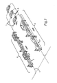
- Figure 1 shows part of a path network for an automated guided vehicle in a motor car assembly line.
- the paths 1 in the network are defined by buried guide wires, from which the automated vehicles 3 obtain guidance for signals.
- the buried wires may provide these guidance signals in a passive manner, i.e. the vehicles detect the presence of the wires and follow them, without the wires providing any signal beyond their mere presence.
- the wires may provide guidance and/or control signals in an active manner, which signals could be picked up for example by electromagnetic transducers on the vehicles. Buried wire guidance systems are known in the art.
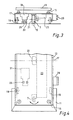
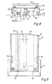
- the wires 5 and the wire-detecting sensor means 7 on the vehicles 3 are best seen in Figures 3 and 8.
- FIG 1 two groups 9 of work stations are shown.
- a vehicle 3 will carry a motor car body shell through the stations of first group, then from the first group to the second group, and then through the stations of the second group.
- the vehicle 3 receives motive power from an external source, and its motion is physically constrained by a track provided at the floor along the length of the group 9 of work stations.
- the vehicles 3 move only by means of their on-board motive power supply, and are guided by the buried wires without being physically constrained by any track.
- the vehicles 3 have safety buffers 11 at either end.
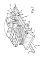
- a frame 13 for carrying a motor car body shell or other article to be assembled is supported by pillars 15 on a vehicle main body 17.
- the main body 17 is supported on the floor of the assembly line principally by freely rotating wheels 19 mounted at either side of the body near its front and rear ends.
- the guide wire sensing means 7 is mounted near the front of the main body, and centrally across the width of the vehicle.
- a further floor contacting wheel 21 is provided near the centre of the vehicle 3. This is a drive wheel which is used to propel the vehicle 3 along those portions of the path where there is no track and no external supply of motive power.
- the vehicle carries electric storage batteries 23 which power an electric motor to drive the wheel 21 over these portions of the path.
- the physically constraining track takes the form of a guide rail 25 mounted on the floor.
- the externally supplied motive power is supplied in the form of electricity, from a supply board 27 (see Figures 1 and 6) mounted alongside the track.
- the vehicle 3 carries a power collector 29 which cooperates with the electric supply board 27 while the vehicle 3 travels over the rail 25.
- the electricity collected by the power collector 29 is used to power a further electric motor 31 mounted on the vehicle 3.
- the motor 31 drives horizontally extending (vertical axis) rollers 33 which press against either side of the floor-mounted rail 25. The reaction between the rollers 33 and the rail 25 drives the vehicle along this portion of its path.
- the vehicle 3 Since the vehicle 3 is receiving a supply of electric power to drive the motor 31 as it passes over the portions of its path having the physically constraining track (in the form of the rail 25), it may be convenient to provide means to recharge the batteries 23 as the vehicle passes along these portions of its path.
- the externally supplied motive power is not supplied to the vehicle in the form of electricity. Instead, it is supplied in the form of a motive force applied directly to the vehicle.
- the physically constraining track takes the form of a line of pairs of horizontally extending rollers 35 mounted just above the floor level of the assembly line.
- the vehicle 3 has a rail 37 which passes between them by the rollers 35 of each pair.
- the vehicle 3 does not carry an additional electric motor 31. Instead, the rollers 35 are driven by motors 39 arranged beneath them.
- the vehicle 3 does not have a further electric motor 31 in this embodiment. it is not necessary to provide a power collector 29 on the vehicle and an electric supply board 27 alongside the track. Nevertheless, it may be convenient to provide a system for supplying the vehicle 3 with electricity as it passes along those portions of its path where it receives external supplied motive power, in order to recharge the batteries 23 carried on the vehicle. Alternatively, no provision may be made for recharging the batteries while the vehicle 3 is travelling on the path 1, and the batteries may be replaced or recharged periodically while the vehicle is being stored, serviced or otherwise not in use.
- each pair of driven rollers 35 may be controlled and driven independently, or the pairs of rollers may be in groups which are driven and controlled together but independently of the rollers of other groups, rather than driving all the rollers associated with one group 9 of work stations under a common control. This division of the rollers into independently driven pairs or groups can allow the vehicles 3 to be driven past the work stations of a group 9 in a more flexible manner.
Landscapes
- Engineering & Computer Science (AREA)
- Transportation (AREA)
- Mechanical Engineering (AREA)
- Chemical & Material Sciences (AREA)
- Combustion & Propulsion (AREA)
- Physics & Mathematics (AREA)
- Electromagnetism (AREA)
- Power Engineering (AREA)
- Manufacturing & Machinery (AREA)
- Control Of Position, Course, Altitude, Or Attitude Of Moving Bodies (AREA)
- Automobile Manufacture Line, Endless Track Vehicle, Trailer (AREA)
- Automatic Assembly (AREA)
- Electric Propulsion And Braking For Vehicles (AREA)
- Control Of Driving Devices And Active Controlling Of Vehicle (AREA)
- Traffic Control Systems (AREA)
- Platform Screen Doors And Railroad Systems (AREA)
Priority Applications (1)
| Application Number | Priority Date | Filing Date | Title |
|---|---|---|---|
| AT88300156T ATE61980T1 (de) | 1987-04-01 | 1988-01-11 | System fuer die benutzung von zwangsgelenkten automatischen fahrzeugen. |
Applications Claiming Priority (2)
| Application Number | Priority Date | Filing Date | Title |
|---|---|---|---|
| GB8707790 | 1987-04-01 | ||
| GB8707790A GB2208499B (en) | 1987-04-01 | 1987-04-01 | Vehicle assembly line having an automated guided vehicle system |
Related Child Applications (2)
| Application Number | Title | Priority Date | Filing Date |
|---|---|---|---|
| EP89113405A Division EP0345826A3 (fr) | 1987-04-01 | 1988-01-11 | Chaíne de montage comprenant un système de véhicules automatiques guidés |
| EP89113405.8 Division-Into | 1988-01-11 |
Publications (2)
| Publication Number | Publication Date |
|---|---|
| EP0285232A1 true EP0285232A1 (fr) | 1988-10-05 |
| EP0285232B1 EP0285232B1 (fr) | 1991-03-27 |
Family
ID=10615050
Family Applications (2)
| Application Number | Title | Priority Date | Filing Date |
|---|---|---|---|
| EP89113405A Ceased EP0345826A3 (fr) | 1987-04-01 | 1988-01-11 | Chaíne de montage comprenant un système de véhicules automatiques guidés |
| EP88300156A Expired - Lifetime EP0285232B1 (fr) | 1987-04-01 | 1988-01-11 | Système utilisant des véhicules automatiques guidés |
Family Applications Before (1)
| Application Number | Title | Priority Date | Filing Date |
|---|---|---|---|
| EP89113405A Ceased EP0345826A3 (fr) | 1987-04-01 | 1988-01-11 | Chaíne de montage comprenant un système de véhicules automatiques guidés |
Country Status (9)
| Country | Link |
|---|---|
| US (1) | US4941407A (fr) |
| EP (2) | EP0345826A3 (fr) |
| JP (1) | JPH01146630A (fr) |
| AT (1) | ATE61980T1 (fr) |
| AU (1) | AU601548B2 (fr) |
| CA (1) | CA1297066C (fr) |
| DE (1) | DE3862136D1 (fr) |
| ES (1) | ES2007161A6 (fr) |
| GB (1) | GB2208499B (fr) |
Cited By (4)
| Publication number | Priority date | Publication date | Assignee | Title |
|---|---|---|---|---|
| DE4032487A1 (de) * | 1989-10-13 | 1991-04-25 | Daifuku Kk | Transportsystem mit selbstangetriebenem plattformwagen |
| WO1991017019A1 (fr) * | 1990-05-08 | 1991-11-14 | Robert Bosch Gmbh | Systeme de transport de pieces |
| EP0942345A1 (fr) * | 1998-03-09 | 1999-09-15 | Jervis B. Webb International Company | Système de guidage pour un véhicule automatique |
| EP1695927A3 (fr) * | 2005-02-24 | 2006-09-06 | Alessandro Gottardo | Dispositif de sélection et de tri des produits |
Families Citing this family (18)
| Publication number | Priority date | Publication date | Assignee | Title |
|---|---|---|---|---|
| DE4002414A1 (de) * | 1990-01-27 | 1991-08-01 | Krause Johann A Maschf | Verfahren und vorrichtung zum transport von gegenstaenden entlang einer fertigungsstrasse |
| DE4240989C2 (de) * | 1992-12-05 | 1997-02-06 | Opel Adam Ag | Flurfördereinrichtung |
| DE4446420A1 (de) * | 1994-12-23 | 1996-06-27 | Indumat Gmbh & Co Kg | Bearbeitungsanlage für Werkstücke |
| DE102007017511C5 (de) * | 2007-04-13 | 2020-01-23 | Eisenmann Se | Antriebseinheit, Antriebssystem und Förderanlage für Skids zum Tragen eines Gegenstandes |
| US20090128139A1 (en) * | 2007-11-20 | 2009-05-21 | Drenth Joseph B | Magnet position locator |
| US8302719B2 (en) * | 2009-03-12 | 2012-11-06 | Honda Motor Co., Ltd. | Vehicle having power stocking mechanism and vehicle system containing the same |
| US8291829B1 (en) | 2010-03-30 | 2012-10-23 | Honda Motor Co., Ltd. | Motorized transport cart and associated part transport system and method |
| CN102765345A (zh) * | 2012-07-23 | 2012-11-07 | 梁倬睿 | 一种道路自动运输装置 |
| KR101416412B1 (ko) * | 2012-12-28 | 2014-07-08 | (주)한진에프에이에스 | 자동차 조립 라인용 부품 운송 시스템 |
| DE102014224082A1 (de) * | 2014-11-26 | 2016-06-02 | Robert Bosch Gmbh | Verfahren zum Betreiben eines Fahrzeugs und zum Betreiben eines Fertigungssystems |
| DE102017106731A1 (de) * | 2017-03-29 | 2018-10-04 | Eisenmann Se | Verfahren und Fahrzeug zum Fördern eines elektrisch angetriebenen Kraftfahrzeugs während dessen Montage |
| USD891493S1 (en) * | 2018-05-15 | 2020-07-28 | Beijing Jingdong Shangke Information Technology Co., Ltd. | Shuttle car for automatic storage system |
| FR3084175B1 (fr) | 2018-07-23 | 2021-04-23 | Reydel Automotive Bv | Systeme et procede automatises de transfert de pieces |
| FR3088919B1 (fr) | 2018-11-28 | 2020-11-06 | Reydel Automotive Bv | Système et procédé automatisés de transfert de pièces |
| FI3908502T3 (fi) * | 2019-01-11 | 2025-07-22 | Duerr Systems Ag | Kuljetuslaite, käsittelylaitos, menettelytapa esineiden kuljettamista ja/tai käsittelyä varten |
| DE102019206491B4 (de) * | 2019-05-06 | 2024-11-14 | Volkswagen Aktiengesellschaft | Fertigungsanlage für Kraftfahrzeuge sowie Fertigungszelle für diese Fertigungsanlage |
| CN111890038B (zh) * | 2020-07-16 | 2022-04-01 | 四川国软科技集团有限公司 | 一种用于前盖的自动装配方法 |
| CN116829443A (zh) * | 2022-01-27 | 2023-09-29 | 宁德时代新能源科技股份有限公司 | 车辆总装生产线和车辆总装的方法 |
Citations (6)
| Publication number | Priority date | Publication date | Assignee | Title |
|---|---|---|---|---|
| CH475895A (de) * | 1966-03-02 | 1969-07-31 | Buero Patent Ag | Automatische gleislose Förderanlage |
| FR2027821A1 (fr) * | 1969-01-06 | 1970-10-02 | Webb Co Jervis B | |
| DD95786A5 (fr) * | 1972-02-22 | 1973-02-12 | ||
| FR2185567A1 (fr) * | 1972-05-19 | 1974-01-04 | Karlsson Sven Torgny | |
| DE3008593A1 (de) * | 1980-03-06 | 1981-09-10 | Translift AG, 6010 Kriens, Luzern | Bodengefuehrte foerder- und transportvorrichtung |
| WO1982000122A1 (fr) * | 1980-07-01 | 1982-01-21 | Bergqvist L | Procede et appareil de telecommande d'un vehicule ou d'un moteur mobile |
Family Cites Families (26)
| Publication number | Priority date | Publication date | Assignee | Title |
|---|---|---|---|---|
| GB347705A (en) * | 1930-01-28 | 1931-04-28 | Wolverhampton Motor Services L | Improvements relating to the propulsion of vehicles |
| GB381157A (en) * | 1930-06-25 | 1932-09-26 | Raymond Rouge | Electric traction system |
| GB396764A (en) * | 1932-02-02 | 1933-08-02 | Armstrong Whitworth Co Eng | Improvements in or relating to electric and engine electric traction |
| GB638918A (en) * | 1947-06-06 | 1950-06-21 | Carlo Mascherpa | A combination mechanical and electrical propulsion plant for vehicles |
| CA677258A (en) * | 1959-10-01 | 1963-12-31 | Arthur M. Barrett, Jr. | Battery charging system for vehicles |
| GB1052624A (fr) * | 1962-12-24 | 1900-01-01 | ||
| US3164103A (en) * | 1963-04-02 | 1965-01-05 | Gen Motors Corp | High speed transit system and vehicle therefor |
| US3537402A (en) * | 1968-05-06 | 1970-11-03 | Hewitt Robins Inc | Drive system |
| US3848535A (en) * | 1971-05-06 | 1974-11-19 | B Mitchell | Rapid transit system |
| US3807312A (en) * | 1972-02-01 | 1974-04-30 | B Flodell | Vehicle propulsion, track, and switch system |
| US3762515A (en) * | 1972-06-07 | 1973-10-02 | Ltv Aerospace Corp | Apparatus for shielding portions of a vehicle |
| US3847085A (en) * | 1973-07-16 | 1974-11-12 | Duo Mode Electric Trans Syst | Dual-mode transportation system |
| DE2402665C2 (de) * | 1974-01-21 | 1984-11-08 | Digitron AG, Brügg, Bern | Fertigungseinrichtung mit selbstfahrenden Transporteinheiten |
| US3886869A (en) * | 1974-06-05 | 1975-06-03 | Rohr Industries Inc | Thrust responsive pinch wheel drive mechanism |
| FR2305329A1 (fr) * | 1975-03-24 | 1976-10-22 | Terracol Claude | Installation de transport bimode |
| DE2531057A1 (de) * | 1975-07-11 | 1977-01-27 | Messerschmitt Boelkow Blohm | Bahnanlage, bei der die spurfuehrung der fahrzeuge auf der strecke abhaengig von laengs der spur sich erstrekkenden passiven leitmitteln erfolgt |
| US4090452A (en) * | 1975-12-11 | 1978-05-23 | Westinghouse Electric Corp. | Power rail, control signal rail and guide beam arrangement for a transporting system |
| JPS5453784A (en) * | 1977-10-07 | 1979-04-27 | Komatsu Ltd | Steering control system for unattended vehicle |
| DE2752027A1 (de) * | 1977-11-22 | 1979-05-23 | Bosch Gmbh Robert | Anordnung zum spurfuehren eines gleisfreien fahrzeuges |
| DE2802635A1 (de) * | 1978-01-21 | 1979-07-26 | Bosch Gmbh Robert | Duo-bus |
| JPS56403A (en) * | 1979-06-16 | 1981-01-06 | Sugiaki Kusatake | Pavement block |
| JPS58144214A (ja) * | 1982-02-19 | 1983-08-27 | Kubota Ltd | テイ−チング・プレイバツク方式の自動走行車輌 |
| US4515235A (en) * | 1982-05-25 | 1985-05-07 | Shinko Electric Co., Ltd. | Driverless guided vehicle |
| JPS596168A (ja) * | 1982-06-30 | 1984-01-13 | 株式会社椿本チエイン | 搬送装置 |
| GB2143395B (en) * | 1983-05-14 | 1986-08-06 | Gen Electric Co Plc | Vehicle guidance and control system |
| US4603753A (en) * | 1983-08-29 | 1986-08-05 | Kubota, Ltd. | Automatic running work vehicle |
-
1987
- 1987-04-01 GB GB8707790A patent/GB2208499B/en not_active Expired - Fee Related
-
1988
- 1988-01-11 EP EP89113405A patent/EP0345826A3/fr not_active Ceased
- 1988-01-11 AT AT88300156T patent/ATE61980T1/de active
- 1988-01-11 EP EP88300156A patent/EP0285232B1/fr not_active Expired - Lifetime
- 1988-01-11 DE DE8888300156T patent/DE3862136D1/de not_active Expired - Fee Related
- 1988-02-12 AU AU11654/88A patent/AU601548B2/en not_active Ceased
- 1988-03-25 ES ES8800915A patent/ES2007161A6/es not_active Expired
- 1988-03-30 CA CA000562917A patent/CA1297066C/fr not_active Expired - Fee Related
- 1988-03-30 US US07/175,109 patent/US4941407A/en not_active Expired - Fee Related
- 1988-04-01 JP JP63082099A patent/JPH01146630A/ja active Pending
Patent Citations (6)
| Publication number | Priority date | Publication date | Assignee | Title |
|---|---|---|---|---|
| CH475895A (de) * | 1966-03-02 | 1969-07-31 | Buero Patent Ag | Automatische gleislose Förderanlage |
| FR2027821A1 (fr) * | 1969-01-06 | 1970-10-02 | Webb Co Jervis B | |
| DD95786A5 (fr) * | 1972-02-22 | 1973-02-12 | ||
| FR2185567A1 (fr) * | 1972-05-19 | 1974-01-04 | Karlsson Sven Torgny | |
| DE3008593A1 (de) * | 1980-03-06 | 1981-09-10 | Translift AG, 6010 Kriens, Luzern | Bodengefuehrte foerder- und transportvorrichtung |
| WO1982000122A1 (fr) * | 1980-07-01 | 1982-01-21 | Bergqvist L | Procede et appareil de telecommande d'un vehicule ou d'un moteur mobile |
Cited By (5)
| Publication number | Priority date | Publication date | Assignee | Title |
|---|---|---|---|---|
| DE4032487A1 (de) * | 1989-10-13 | 1991-04-25 | Daifuku Kk | Transportsystem mit selbstangetriebenem plattformwagen |
| WO1991017019A1 (fr) * | 1990-05-08 | 1991-11-14 | Robert Bosch Gmbh | Systeme de transport de pieces |
| EP0942345A1 (fr) * | 1998-03-09 | 1999-09-15 | Jervis B. Webb International Company | Système de guidage pour un véhicule automatique |
| US6272406B2 (en) | 1998-03-09 | 2001-08-07 | Jervis B. Webb Company | Guidance system for an automated guided-vehicle |
| EP1695927A3 (fr) * | 2005-02-24 | 2006-09-06 | Alessandro Gottardo | Dispositif de sélection et de tri des produits |
Also Published As
| Publication number | Publication date |
|---|---|
| AU1165488A (en) | 1988-10-06 |
| DE3862136D1 (de) | 1991-05-02 |
| GB2208499B (en) | 1991-07-10 |
| ATE61980T1 (de) | 1991-04-15 |
| AU601548B2 (en) | 1990-09-13 |
| EP0345826A2 (fr) | 1989-12-13 |
| EP0285232B1 (fr) | 1991-03-27 |
| GB2208499A (en) | 1989-04-05 |
| GB8707790D0 (en) | 1987-05-07 |
| JPH01146630A (ja) | 1989-06-08 |
| EP0345826A3 (fr) | 1989-12-27 |
| CA1297066C (fr) | 1992-03-10 |
| ES2007161A6 (es) | 1989-06-01 |
| US4941407A (en) | 1990-07-17 |
Similar Documents
| Publication | Publication Date | Title |
|---|---|---|
| US4941407A (en) | Automated guided vehicle system | |
| CA2027319A1 (fr) | Transporteur a plates-formes automotrices | |
| US8733252B2 (en) | Electric monorail part carrier | |
| US3780666A (en) | Transportation | |
| US3532060A (en) | Transportation system and vehicle | |
| CN211056041U (zh) | 一种轨道式子母车 | |
| KR101828160B1 (ko) | 무가선 노면 전차 시스템 | |
| JP2819657B2 (ja) | 無人車におけるトロリ式充電装置 | |
| CN205713320U (zh) | 一种全向自动存取交接机器人及自动停车场 | |
| JP3575925B2 (ja) | 分岐軌道を備えた搬送設備 | |
| CN114132179A (zh) | 输送分拣小车及供电方法 | |
| US3777670A (en) | Single-directional track-guided vehicle | |
| EP0146393B1 (fr) | Bogie de sustentation du cable tracteur d'un funiculaire | |
| ES2097563T3 (es) | Unidad de transporte de una instalacion transportadora a la altura del suelo. | |
| KR100523272B1 (ko) | 분기궤도를 구비한 반송설비 | |
| JP2706344B2 (ja) | 多段搬送台車のトロリー線接続装置 | |
| US20210100374A1 (en) | Intelligent meal delivery system | |
| CN212172400U (zh) | 一种新型差速agv移动平台 | |
| JP3261424B2 (ja) | 入出庫用電車の給電装置 | |
| JPS59103112A (ja) | 搬送設備における搬送台車制御方法 | |
| JPH0235801B2 (ja) | Jikifujoshikitetsudonokidobunkisochi | |
| CN119795803A (zh) | 一种路轨两用麦轮底盘车及其控制方法 | |
| JP3422480B2 (ja) | 無人搬送車システム | |
| JPH0956926A (ja) | 遊技装置の給電構造 | |
| JPH04345412A (ja) | 入出庫用電車利用の自動倉庫 |
Legal Events
| Date | Code | Title | Description |
|---|---|---|---|
| PUAI | Public reference made under article 153(3) epc to a published international application that has entered the european phase |
Free format text: ORIGINAL CODE: 0009012 |
|
| AK | Designated contracting states |
Kind code of ref document: A1 Designated state(s): AT BE CH DE FR GB GR IT LI LU NL SE |
|
| 17P | Request for examination filed |
Effective date: 19881019 |
|
| RAP1 | Party data changed (applicant data changed or rights of an application transferred) |
Owner name: LITTON U.K. LIMITED |
|
| RAP1 | Party data changed (applicant data changed or rights of an application transferred) |
Owner name: LITTON U.K. LIMITED |
|
| 17Q | First examination report despatched |
Effective date: 19890428 |
|
| ITF | It: translation for a ep patent filed | ||
| GRAA | (expected) grant |
Free format text: ORIGINAL CODE: 0009210 |
|
| AK | Designated contracting states |
Kind code of ref document: B1 Designated state(s): AT BE CH DE FR GB GR IT LI LU NL SE |
|
| PG25 | Lapsed in a contracting state [announced via postgrant information from national office to epo] |
Ref country code: LI Effective date: 19910327 Ref country code: GR Free format text: LAPSE BECAUSE OF FAILURE TO SUBMIT A TRANSLATION OF THE DESCRIPTION OR TO PAY THE FEE WITHIN THE PRESCRIBED TIME-LIMIT Effective date: 19910327 Ref country code: CH Effective date: 19910327 Ref country code: AT Effective date: 19910327 |
|
| REF | Corresponds to: |
Ref document number: 61980 Country of ref document: AT Date of ref document: 19910415 Kind code of ref document: T |
|
| REF | Corresponds to: |
Ref document number: 3862136 Country of ref document: DE Date of ref document: 19910502 |
|
| ET | Fr: translation filed | ||
| REG | Reference to a national code |
Ref country code: CH Ref legal event code: PL |
|
| PG25 | Lapsed in a contracting state [announced via postgrant information from national office to epo] |
Ref country code: GB Effective date: 19920111 |
|
| PG25 | Lapsed in a contracting state [announced via postgrant information from national office to epo] |
Ref country code: SE Effective date: 19920112 |
|
| PLBE | No opposition filed within time limit |
Free format text: ORIGINAL CODE: 0009261 |
|
| STAA | Information on the status of an ep patent application or granted ep patent |
Free format text: STATUS: NO OPPOSITION FILED WITHIN TIME LIMIT |
|
| PG25 | Lapsed in a contracting state [announced via postgrant information from national office to epo] |
Ref country code: LU Free format text: LAPSE BECAUSE OF NON-PAYMENT OF DUE FEES Effective date: 19920131 Ref country code: BE Effective date: 19920131 |
|
| 26N | No opposition filed | ||
| BERE | Be: lapsed |
Owner name: LITTON U.K. LTD Effective date: 19920131 |
|
| PG25 | Lapsed in a contracting state [announced via postgrant information from national office to epo] |
Ref country code: NL Effective date: 19920801 |
|
| GBPC | Gb: european patent ceased through non-payment of renewal fee | ||
| NLV4 | Nl: lapsed or anulled due to non-payment of the annual fee | ||
| PG25 | Lapsed in a contracting state [announced via postgrant information from national office to epo] |
Ref country code: FR Effective date: 19920930 |
|
| PG25 | Lapsed in a contracting state [announced via postgrant information from national office to epo] |
Ref country code: DE Effective date: 19921001 |
|
| REG | Reference to a national code |
Ref country code: FR Ref legal event code: ST |
|
| EUG | Se: european patent has lapsed |
Ref document number: 88300156.2 Effective date: 19920806 |
|
| PG25 | Lapsed in a contracting state [announced via postgrant information from national office to epo] |
Ref country code: IT Free format text: LAPSE BECAUSE OF NON-PAYMENT OF DUE FEES;WARNING: LAPSES OF ITALIAN PATENTS WITH EFFECTIVE DATE BEFORE 2007 MAY HAVE OCCURRED AT ANY TIME BEFORE 2007. THE CORRECT EFFECTIVE DATE MAY BE DIFFERENT FROM THE ONE RECORDED. Effective date: 20050111 |