EP0289723A2 - Vorrichtung zur Verhinderung von Überdrehzahlen für eine Brennkraftmaschine - Google Patents
Vorrichtung zur Verhinderung von Überdrehzahlen für eine Brennkraftmaschine Download PDFInfo
- Publication number
- EP0289723A2 EP0289723A2 EP88102694A EP88102694A EP0289723A2 EP 0289723 A2 EP0289723 A2 EP 0289723A2 EP 88102694 A EP88102694 A EP 88102694A EP 88102694 A EP88102694 A EP 88102694A EP 0289723 A2 EP0289723 A2 EP 0289723A2
- Authority
- EP
- European Patent Office
- Prior art keywords
- engine
- valve
- actuator
- control valve
- vibrating pump
- Prior art date
- Legal status (The legal status is an assumption and is not a legal conclusion. Google has not performed a legal analysis and makes no representation as to the accuracy of the status listed.)
- Withdrawn
Links
Images


Classifications
-
- F—MECHANICAL ENGINEERING; LIGHTING; HEATING; WEAPONS; BLASTING
- F02—COMBUSTION ENGINES; HOT-GAS OR COMBUSTION-PRODUCT ENGINE PLANTS
- F02D—CONTROLLING COMBUSTION ENGINES
- F02D17/00—Controlling engines by cutting out individual cylinders; Rendering engines inoperative or idling
- F02D17/04—Controlling engines by cutting out individual cylinders; Rendering engines inoperative or idling rendering engines inoperative or idling, e.g. caused by abnormal conditions
Definitions
- the present invention relates to a device for inhibiting overrunning of the internal combustion engine in use of its vibrations.
- Portable working machines generally use a two-stroke engine as a power source.
- a diaphragm type carbureter is employed to thereby make it possible to operate a machine in all attitudes.
- the two-stroke engine is used for a chain saw, a brush cutter, etc. It is generally that such a portable working machine is operated with the light-weight, small-size and high-output internal combustion engine fully loaded in order to enhance the working properties.
- the engine when a throttle valve of a carbureter is totally opened where a load torque at the time of unloaded operation is small, the engine brings forth a so-called overrunning by which an allowable number of revolutions exceeds before cutting work takes place to sometimes damage the engine. The overrunning operation likewise occurs also after the cutting work has been completed.
- the overrunning may be avoided if the throttle valve is restored every time of interruption of the work so as not to effect the no-load running when the throttle valve is totally opened.
- the operator often fails to do so, thus resulting in damages of and shortening of life of the engine.
- the present invention has proposed an anti-overrunning device as disclosed in Japanese Patent Application Laid-Open No. 1835/1986.
- a vibrating pump is normally driven to directly supply pressure air to an actuator, and therefore, a diaphragm of the vibrating pump is always unsteady due to the vibrations of the engine; the operating stability is poor; and it is difficult to set an actuating point at which a throttle valve is closed by an actuator during overrunning of the engine.
- the present invention provides an arrangement which comprises a vibration pump for generating pneumatic pressure by vibrations of the engine; an actuator for actuating a throttle valve of a carbureter in a direction of closing the valve; and a control valve for controlling a flow of the pneumatic pressure from said vibrating pump to actuator during overrunning of the engine; and said control valve being actuated by virtue of the electromotive force of a generator driven by the engine.
- the present invention comprises a vibrating pump for generating pneumatic pressure by vibrations of the engine; an actuator for actuating a throttle valve os a carbureter in a direction of closing the valve; and a control valve for controlling a flow of the pneumatic pressure from said vibrating pump to actuator during overrunning of the engine; and said control valve being actuated by virtue of the electromotive force of a generator driven by the engine.
- the actuation of the vibrating pump or the actuator is cancelled and released, and therefore, the relationship between the voltage of the generator driven by the engine to actuate the electromagnetic valve and the number of revolutions of the engine is very stable.
- the control valve is less in unevenness, positive in operation and reliability thereof is enhanced.
- the opening degree of the throttle valve of the carbureter is automatically reduced when the engine is overrun to reduce the flow rate of a mixture taken into the engine. Therefore, there is provided a new anti-overrunning device which is positive in operation, may be run at a substantially reasonable fuel cost (rate of fuel consumption) in all running levels of the engine, is free of spark plug from a fog, is less in exhaust fume, and is less tar stayed on the muffler.
- the operator can perform his work while a throttle handle is left fully opened, because of actuation of the anti-overrunning device the working properties may be enhanced, and the damage of and the shortening of life of the engine may be avoided.
- a carbureter 24 and a muffler 12 are connected to one and the other, respectively, of a cylinder body 11 having cooling fins.
- the generator 13 driven by the crank shaft 15, and the electromotive force of the generator is utilized to intermittently apply a high voltage to the ignition plug so as to produce an electric spark.
- a throttle vale 27 is supported by the valve shaft 28 on a venturi 34 formed on the body 35 of carbureter 24, and fuel is supplied to the venturi 34 by negative pressure of air passing through the venturi 34.
- fuel supplying mechanism is known, for example, in US Patent No. 3738623 and directly has nothing to do with the gist of the present invention , and will not be further described.
- valve shaft 28 An upper end of the valve shaft 28 is rotatably supported on the body 35 by means of a bearing sleeve 38, and an inverted-L shaped throttle valve lever 29 is secured to the upper end.
- One end of a spring 36 wound around the valve shaft 28 is placed in engagement with the throttle valve lever 29 and the other end thereof placed in engagement with the bearing sleeve 38.
- a boss portion of the lever 25 is slipped over the bearing sleeve 38, and one end of a spring 32 wound around the boss portion is placed in engagement with the lever 25 whereas the other end is placed in engagement with a pin 31 of the body 35.
- An engaging portion 37 of the throttle valve lever 29 is projected downwardly so that it may engage with the edge of the lever 25.
- the throttle valve lever 29 is pivotally urged counterclockwise by the force of the spring 36 to cause the engaging portion 37 to abut against the lever 25.
- the lever 25 is pivotally urged clockwise by the strong force of the spring 32 to close the throttle valve 27.
- the throttle valve lever 29 also follows the lever 25 to increase an opening degree of the throttle valve 27.
- the anti-overrunning device for the internal combustion engine is composed of a vibrating pump 41, a control valve 61 and an actuator 81 for reducing an opening degree of the throttle valve 27 by the throttle valve lever 29.
- the vibrating pump 41 has a diaphragm 58 sandwiched between cup-like housings 57 and 55 to form an atmospheric chamber 45 and a pressure chamber 46.
- Pad plates 42 and 51 are placed on both surfaces of a diaphragm 58, and a weight 44 is connected by means of a rivet 43.
- the pressure chamber 46 is provided with passages 56 and 47, to which port members 53 and 50, respectively, are connected.
- the port member 53 is provided with a check valve 54 to allow a flow of air from the passage 56 to a passage 52.
- the port member 50 is provided with a check valve 48 to allow a flow of air from an atmospheric opening 49 to the passage 47.
- the passage 52 is connected to a passage 68 of the control valve 61 by a pipe 17.
- the control valve 61 is in the form of a normally closed type electromagnetic valve, and passages 68 and 71 are provided in the housing 67 and a valve body 69 is urged by the force of the spring 64 against the valve seat 70 formed in the connection of said passages.
- the valve body 69 integral with the plunger, and when the electromagnetic coil 66 is excited, the valve body 69 is attracted against the force of the spring 64 and moved away from the valve seat 70.
- a bobbin of the coil 66 is accommodated in a cup-shaped core 63 and closed by a core 65 formed from an annular plate, said core 65 being placed on and coupled to the end wall of the housing 67.
- An armature 62 coupled to the core 63 and a plunger integral with the valve body 69 are inserted into the bobbin of the electromagnetic coil 66, and a spring 64 is interposed between the plunger and the armature 62.
- the electromotive force of the generator 13 is applied to the electromagnetic coil 66.
- the electromotive force of the generator 13 is applied as an input to an electronic controller 14, and then applied, through a switching circuit actuated when said voltage exceeds a predetermined value, to the electromagnetic coil 66.
- a passage 71 is connected to the pressure chamber 85 of the actuator 81 through the pipe 18.
- the actuator 81 has a diaphragm 84 sandwiched between cup-like housings 82 and 83 to form a pressure chamber 85 and an atmospheric chamber 86.
- Pad plates 87 and 88 are placed on both surfaces of the diaphragm 84, the plates being connected by the base end of a rod 92.
- the rod 92 slidably inserted into a hole 91 of the housing 83 is retracted by means of a spring 89 surrounding the rod 92 and interposed between the pad plate 88 and the housing 83.
- the fore end of the rod 92 is placed into abutment with the aforementioned throttle valve lever 29.
- the pressure chamber 85 and the atmospheric chamber 86 are provided with orifices 93 and 94 in communication with atmosphere, respectively, whereby the extreme operation of the actuator 81 may be restricted.
- the above-described vibrating pump 41 is preferably integrally connected to the lower end wall of the body 35 of the carbureter 24, and the control valve 61 and the actuator 81 are connected to the upper end wall of the body 35, as shown in Fig. 3.
- the housing of the control valve 61 is integrally formed with the housing 82 of the actuator 81.
- the vibrating pump 41 and the control valve 61 are connected by the pipe 17.
- the vibrating pump 41 and the control valve 61 may be mounted suitably on the engine 10.
- an electromotive force or voltage of a generator 13 driven by the engine 10 becomes higher than a predetermined value.
- an electromagnetic force of an electromagnetic coil 66 of the control valve 61 is greater than the force of a spring 64, and the valve body 69 integral with the plunger is moved away from the valve seat 70 to release the cancellation of the vibrating pump 41 and the actuator 81.
- the vibrating pump 41 Upon receipt of the vibration of the engine, the vibrating pump 41 vibrates up and down by the weight 44 supported on the diaphragm 58.
- the diaphragm 58 When the diaphragm 58 is inflated upwardly, pressure of the pressure chamber 46 lowers, and therefore the check valve 48 opens to take air into the pressure chamber 46 from the atmospheric opening 49. Subsequently, when the diaphragm 58 is inflated downwardly, the air of the pressure chamber 46 causes the check valve 54 to open and is discharged toward the pipe 17.
- the passage 68 since the passage 68 remains closed, when the pressure in the pressure chamber 46 is relatively higher, the vibration of the diaphragm 58 is inhibited.
- the electromotive force applied from the generator 13 to the electromagnetic coil 66 of the control valve 61 increases, and the electromotive force of the electromagnetic coil 66 exerting on the valve body 69 becomes greater than the force of the spring 64 whereby the valve body 69 is moved away from the valve seat 70 to provide communication between the passage 68 and the passage 71 or the pressure chamber 85.
- the diaphragm 58 of the vibrating pump 41 is greatly vibrated by the weight 44, the pressure air in the pressure chamber 46 is supplied to the pressure chamber 85 of the actuator 81 through the control valve 61, and the rod 92 is forced down against the force of the spring 89.
- the throttle valve lever 29 is rotated clockwise along with the valve shaft 28, as shown by the chain lines in Fig. 3, and the opening degree of the throttle valve 27 is reduced.
- the flow rate of the mixture taken into the engine is reduced, and the number of revolutions of the engine decreases.
- the opening degree of the throttle valve 27 is determined depending on the rotated position of the lever 25 operated by the trigger wire 30.
- the control valve 61 again opens, and the opening degree of the throttle valve 27 is decreased by the actuator 81. The operation as described above is repeated whereby the engine is maintained less than a predetermined number of revolutions, and the overrunning of the engine is automatically prevented without the operator's operation of the trigger wire 30 according to the variation of load.
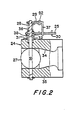
- the actuator 181 is actuated via the control valve 61 by negative pressure generated by the vibrating pump 141.
- the housing 67 of the control valve 61 is integral with the port member 153 of the vibrating pump 141, and the valve seat 70 is disposed between the passage 68 and the passage 149.
- the pressure chamber 185 of the actuator 181 is communicated with the passage 68 of the control valve 61 through the pipe 19.
- the other structures are similar to those of the embodiment shown in Fig. 1, and similar members for the actuator and vibrating pump are indicated by reference numerals to which 100 is added.
- the valve body 69 of the control valve 61 is moved away from the valve seat 70. Accordingly, air in the pressure chamber 185 of the actuator 181 is taken into the pressure chamber 146 of the vibrating pump 141 through the pipe 19, the passage 68, valve seat 70, passage 149 and check valve 148, and thence discharged from the passage 152 through the check valve 154 to outside.
- the pressure chamber 185 is negative in pressure
- the rod 192 is urged down against the force of the spring 189
- the throttle valve 27 along with the throttle valve lever 29 is rotated in the direction of closing the valve.
- control valve is provided between the vibrating pump and the actuator
- a control valve may be connected to an inlet port of a vibrating pump so as to actuate the vibrating pump only during overrunning of the engine
- a control valve may be connected to a pressure chamber of an actuator so as to normally actuate the actuator in the reverse direction and to actuate it in the normal direction by the force of the spring during the overrunning of the engine.
- control valve 61 is connected to the inlet side of the vibrating pump 41, namely, to the side of the check valve 48.
- the housing of the control valve 61 is integrally formed with a port member 50.
- An outlet port of the vibrating pump 41, that is, the side of the check valve 54 is connected to a pressure chamber 85 of an actuator 81 by means of a pipe 20.
- the structures of the vibrating pump 41, actuator 81 and control valve 61 are similar to those in the embodiment shown in Fig. 3. Similar members are indicated by the reference numerals previously used and further description thereof will be omitted.
- the diaphragm 58 of the vibrating pump 41 subjected to the vibration of the engine is reciprocated to supply pressure air from the pressure chamber 46 to the pressure chamber 85 of the actuator 81 through the pipe 20, the rod 92 is forced down against the force of the spring 89, and the throttle valve 27 is rotated along with the throttle valve lever 29 in the direction of closing the valve.
- the vibrating pump 41 is connected to the actuator 81 through a pipe 21.
- the control valve 61 is integrally formed with the housing of the actuator 81, the passage 68 is communicated with the pressure chamber 85 of the actuator 81 through the pipe 22, and the passage 71 is opened to the atmosphere.
- the actuator 81 causes the rod 92 to be forced downard by the virtue of the force of the spring 89a accommodated in the atmospheric chamber 86.
- the other structures are similar to those shown in Fig. 3, and similar members are indicated by the reference numerals previously used, and further description thereof will be omitted.
Landscapes
- Engineering & Computer Science (AREA)
- Chemical & Material Sciences (AREA)
- Combustion & Propulsion (AREA)
- Mechanical Engineering (AREA)
- General Engineering & Computer Science (AREA)
- Control Of Throttle Valves Provided In The Intake System Or In The Exhaust System (AREA)
- Output Control And Ontrol Of Special Type Engine (AREA)
- Electrical Control Of Air Or Fuel Supplied To Internal-Combustion Engine (AREA)
Applications Claiming Priority (2)
| Application Number | Priority Date | Filing Date | Title |
|---|---|---|---|
| JP62110117A JP2563173B2 (ja) | 1987-05-06 | 1987-05-06 | 内燃機関の過回転防止装置 |
| JP110117/87 | 1987-05-06 |
Publications (2)
| Publication Number | Publication Date |
|---|---|
| EP0289723A2 true EP0289723A2 (de) | 1988-11-09 |
| EP0289723A3 EP0289723A3 (de) | 1989-08-30 |
Family
ID=14527469
Family Applications (1)
| Application Number | Title | Priority Date | Filing Date |
|---|---|---|---|
| EP88102694A Withdrawn EP0289723A3 (de) | 1987-05-06 | 1988-02-23 | Vorrichtung zur Verhinderung von Überdrehzahlen für eine Brennkraftmaschine |
Country Status (3)
| Country | Link |
|---|---|
| US (1) | US4796583A (de) |
| EP (1) | EP0289723A3 (de) |
| JP (1) | JP2563173B2 (de) |
Families Citing this family (4)
| Publication number | Priority date | Publication date | Assignee | Title |
|---|---|---|---|---|
| JPH0545534Y2 (de) * | 1987-12-16 | 1993-11-22 | ||
| US7204821B1 (en) | 2000-01-31 | 2007-04-17 | Ethicon, Inc. | Surgical fluid management system with suction control |
| EP2074325B1 (de) * | 2006-10-17 | 2010-01-06 | Selettra S.r.l. | Membranvergaser mit elektromagnetischem stellantrieb |
| US7927319B2 (en) * | 2007-02-20 | 2011-04-19 | Kci Licensing, Inc. | System and method for distinguishing leaks from a disengaged canister condition in a reduced pressure treatment system |
Family Cites Families (6)
| Publication number | Priority date | Publication date | Assignee | Title |
|---|---|---|---|---|
| US4365600A (en) * | 1980-08-01 | 1982-12-28 | Isuzu Motors, Limited | Diesel throttle valve control system |
| JPS5946344A (ja) * | 1982-03-03 | 1984-03-15 | Walbro Far East | 2サイクルエンジン過回転防止装置 |
| JPS58172439A (ja) * | 1982-04-01 | 1983-10-11 | Walbro Far East | 電磁変換式エンヂン過回転防止装置 |
| JPS60228736A (ja) * | 1984-04-25 | 1985-11-14 | Mitsubishi Heavy Ind Ltd | 気化器 |
| JPS60261940A (ja) * | 1984-06-08 | 1985-12-25 | Walbro Far East | 2サイクル内燃機関の過回転防止装置 |
| JPS611835A (ja) * | 1984-06-13 | 1986-01-07 | Walbro Far East | 2サイクル内燃機関の過回転防止装置 |
-
1987
- 1987-05-06 JP JP62110117A patent/JP2563173B2/ja not_active Expired - Lifetime
- 1987-09-29 US US07/102,354 patent/US4796583A/en not_active Expired - Fee Related
-
1988
- 1988-02-23 EP EP88102694A patent/EP0289723A3/de not_active Withdrawn
Also Published As
| Publication number | Publication date |
|---|---|
| EP0289723A3 (de) | 1989-08-30 |
| JP2563173B2 (ja) | 1996-12-11 |
| US4796583A (en) | 1989-01-10 |
| JPS63277825A (ja) | 1988-11-15 |
Similar Documents
| Publication | Publication Date | Title |
|---|---|---|
| US6374782B2 (en) | Air-fuel mixture generating device | |
| JP2011106457A (ja) | 内燃エンジンの作動方法 | |
| EP0289723A2 (de) | Vorrichtung zur Verhinderung von Überdrehzahlen für eine Brennkraftmaschine | |
| JPS639663A (ja) | エンジンで駆動される手動操作装置の気化器における空気/燃料−混合気の比を変えるための装置 | |
| EP0285808B1 (de) | Vorrichtung zur Verhinderung von Überdrehzahlen für eine Brennkraftmaschine | |
| JP4892272B2 (ja) | 燃料系における電磁弁制御方法 | |
| EP0289722A2 (de) | Vorrichtung zur Verhinderung von Überdrehzahlen für eine Brennkraftmaschine | |
| EP0285809A2 (de) | Vorrichtung zur Verhinderung von Überdrehzahlen für eine Brennkraftmaschine | |
| US4809658A (en) | Anti-overrunning device for an internal combustion engine | |
| US6000370A (en) | Compression release mechanism for an internal combustion engine | |
| US4542726A (en) | Deceleration enrichment fuel system for an internal combustion engine | |
| JP2835928B2 (ja) | 小型エンジンにおける始動円滑化装置 | |
| US4211197A (en) | Compressive pressure augmentation device | |
| JPH03253728A (ja) | 内燃機関の過回転防止装置 | |
| JPH03249361A (ja) | 気化器の自動チヨーク装置 | |
| JPS5919790Y2 (ja) | 内燃機関のアンダピストンポンプ切換弁装置 | |
| JPS5927327Y2 (ja) | ディ−ゼル機関車の液体変速機の制御装置 | |
| JP2504894Y2 (ja) | 汎用エンジンのオ―トアイドル装置 | |
| JPH03138441A (ja) | 内燃機関の燃料制御装置 | |
| KR20030029667A (ko) | 디젤엔진의 키이-오프시 2차폭발 방지장치 | |
| JPH1018931A (ja) | クランクケース圧縮式2サイクルエンジンの燃料供給装置 | |
| JPH0874666A (ja) | ガバナ機構付きエンジン | |
| JPH039070A (ja) | ディーゼルエンジンの始動装置 | |
| JPS60201032A (ja) | デイ−ゼルエンジンの振動低減装置 | |
| JPH068607B2 (ja) | デイ−ゼルエンジンの吸気装置 |
Legal Events
| Date | Code | Title | Description |
|---|---|---|---|
| PUAI | Public reference made under article 153(3) epc to a published international application that has entered the european phase |
Free format text: ORIGINAL CODE: 0009012 |
|
| AK | Designated contracting states |
Kind code of ref document: A2 Designated state(s): BE DE FR GB IT SE |
|
| PUAL | Search report despatched |
Free format text: ORIGINAL CODE: 0009013 |
|
| AK | Designated contracting states |
Kind code of ref document: A3 Designated state(s): BE DE FR GB IT SE |
|
| 17P | Request for examination filed |
Effective date: 19900216 |
|
| 17Q | First examination report despatched |
Effective date: 19900709 |
|
| STAA | Information on the status of an ep patent application or granted ep patent |
Free format text: STATUS: THE APPLICATION IS DEEMED TO BE WITHDRAWN |
|
| 18D | Application deemed to be withdrawn |
Effective date: 19901120 |