EP0295164A1 - Verfahren zum Schreiben von Synchronisierungsinformation auf einen magnetischen Augzeichnungsträger - Google Patents
Verfahren zum Schreiben von Synchronisierungsinformation auf einen magnetischen Augzeichnungsträger Download PDFInfo
- Publication number
- EP0295164A1 EP0295164A1 EP88401246A EP88401246A EP0295164A1 EP 0295164 A1 EP0295164 A1 EP 0295164A1 EP 88401246 A EP88401246 A EP 88401246A EP 88401246 A EP88401246 A EP 88401246A EP 0295164 A1 EP0295164 A1 EP 0295164A1
- Authority
- EP
- European Patent Office
- Prior art keywords
- information
- sub
- sequence
- group
- subgroup
- Prior art date
- Legal status (The legal status is an assumption and is not a legal conclusion. Google has not performed a legal analysis and makes no representation as to the accuracy of the status listed.)
- Granted
Links
Images


Classifications
-
- G—PHYSICS
- G11—INFORMATION STORAGE
- G11B—INFORMATION STORAGE BASED ON RELATIVE MOVEMENT BETWEEN RECORD CARRIER AND TRANSDUCER
- G11B5/00—Recording by magnetisation or demagnetisation of a record carrier; Reproducing by magnetic means; Record carriers therefor
- G11B5/48—Disposition or mounting of heads or head supports relative to record carriers ; arrangements of heads, e.g. for scanning the record carrier to increase the relative speed
- G11B5/58—Disposition or mounting of heads or head supports relative to record carriers ; arrangements of heads, e.g. for scanning the record carrier to increase the relative speed with provision for moving the head for the purpose of maintaining alignment of the head relative to the record carrier during transducing operation, e.g. to compensate for surface irregularities of the latter or for track following
- G11B5/596—Disposition or mounting of heads or head supports relative to record carriers ; arrangements of heads, e.g. for scanning the record carrier to increase the relative speed with provision for moving the head for the purpose of maintaining alignment of the head relative to the record carrier during transducing operation, e.g. to compensate for surface irregularities of the latter or for track following for track following on disks
- G11B5/59633—Servo formatting
-
- G—PHYSICS
- G11—INFORMATION STORAGE
- G11B—INFORMATION STORAGE BASED ON RELATIVE MOVEMENT BETWEEN RECORD CARRIER AND TRANSDUCER
- G11B20/00—Signal processing not specific to the method of recording or reproducing; Circuits therefor
- G11B20/10—Digital recording or reproducing
- G11B20/12—Formatting, e.g. arrangement of data block or words on the record carriers
- G11B20/1217—Formatting, e.g. arrangement of data block or words on the record carriers on discs
-
- G—PHYSICS
- G11—INFORMATION STORAGE
- G11B—INFORMATION STORAGE BASED ON RELATIVE MOVEMENT BETWEEN RECORD CARRIER AND TRANSDUCER
- G11B27/00—Editing; Indexing; Addressing; Timing or synchronising; Monitoring; Measuring tape travel
- G11B27/10—Indexing; Addressing; Timing or synchronising; Measuring tape travel
- G11B27/19—Indexing; Addressing; Timing or synchronising; Measuring tape travel by using information detectable on the record carrier
- G11B27/28—Indexing; Addressing; Timing or synchronising; Measuring tape travel by using information detectable on the record carrier by using information signals recorded by the same method as the main recording
- G11B27/30—Indexing; Addressing; Timing or synchronising; Measuring tape travel by using information detectable on the record carrier by using information signals recorded by the same method as the main recording on the same track as the main recording
- G11B27/3027—Indexing; Addressing; Timing or synchronising; Measuring tape travel by using information detectable on the record carrier by using information signals recorded by the same method as the main recording on the same track as the main recording used signal is digitally coded
-
- G—PHYSICS
- G11—INFORMATION STORAGE
- G11B—INFORMATION STORAGE BASED ON RELATIVE MOVEMENT BETWEEN RECORD CARRIER AND TRANSDUCER
- G11B20/00—Signal processing not specific to the method of recording or reproducing; Circuits therefor
- G11B20/10—Digital recording or reproducing
- G11B20/12—Formatting, e.g. arrangement of data block or words on the record carriers
- G11B2020/1264—Formatting, e.g. arrangement of data block or words on the record carriers wherein the formatting concerns a specific kind of data
- G11B2020/1265—Control data, system data or management information, i.e. data used to access or process user data
- G11B2020/1281—Servo information
- G11B2020/1282—Servo information in embedded servo fields
-
- G—PHYSICS
- G11—INFORMATION STORAGE
- G11B—INFORMATION STORAGE BASED ON RELATIVE MOVEMENT BETWEEN RECORD CARRIER AND TRANSDUCER
- G11B2220/00—Record carriers by type
- G11B2220/20—Disc-shaped record carriers
-
- G—PHYSICS
- G11—INFORMATION STORAGE
- G11B—INFORMATION STORAGE BASED ON RELATIVE MOVEMENT BETWEEN RECORD CARRIER AND TRANSDUCER
- G11B2220/00—Record carriers by type
- G11B2220/20—Disc-shaped record carriers
- G11B2220/25—Disc-shaped record carriers characterised in that the disc is based on a specific recording technology
- G11B2220/2525—Magneto-optical [MO] discs
Definitions
- the present invention relates to a method of writing information on a magnetic recording medium. It is more particularly applicable to memories with magnetooptical discs.
- the mode of operation is based on the magnetooptical effect which concerns the interaction of a rectilinear polarized light with the magnetic state of the material constituting the recording layer of magnetic discs.
- the information is read by an optoelectronic device comprising a more or less complex focusing optical device associated with photoelectronic transducers and circuits for amplifying the signals delivered by these transducers.
- opto-electronic devices make it possible to observe a face of a disc at a given moment, by a beam of polarized light, and to deliver an electrical signal whose voltage (or current) is a function of the value of the information located there.
- magnetic disks carry this information in binary coded form on circular concentric recording tracks whose width is of the order of a few micrometers and which are arranged on their two faces.
- Each track is identified by a serial number j, j being an integer varying from zero to N - 1, N being the total number of recording tracks. This number of tracks is of the order of several thousand.
- the coded expression of the serial number j of a track is called an address. In this case, the address is called "absolute address”.
- Magnetic discs have a constant rotational speed.
- a minimum of space is reserved on the one hand for recording the addresses of the tracks and on the other hand for recording information necessary for the position control above the tracks of the magnetic transducer associated with this face, this information also being called “fine position information”.
- each face of the disc are preferably distributed over equal and adjacent circular sectors S0, S1, ..., S i , ..., S n .
- one side of the disc is divided into several tens of sectors (of the order of 80 to 90 sectors, for example).
- Each sector S i is itself divided into two unequal areas.
- the largest area includes the data intended to be processed by the information processing system to which the disk memory belongs while the smallest area includes the addresses of the tracks and the fine position information.
- the smallest area is divided into several areas called reference areas.
- Each track is associated with at least one zone having the same serial number j as this one.
- a blank area containing no information is placed between the largest area and the smallest area. It precedes the latter.
- Each reference zone comprises three parts, namely, a first part called the preamble preceding a second part containing address information, itself preceding a third part comprising fine position information.
- the preamble part contains information whose exploitation by the reading circuits of the disk memory makes it possible to determine the gain of the amplifiers of these circuits so that the reading accuracy of the addresses and of fine position information is the greatest possible.
- a small part of this information placed at the start of the preamble part (generally one or two pieces of information) can also serve as synchronization information making it possible to determine the start of each reference zone.
- the writing mode briefly recalled above used in conventional disk memories is transposable and applicable to magneto-optical disk memories provided that the following disadvantage is overcome: -
- the part containing preamble information is ill-suited to its use in memories with magnetooptical discs. Indeed, the discs used in these memories have an error rate of the order of 10 ⁇ 5 (one error in 105 written information) considered to be relatively high.
- the first part containing the preamble information serving simultaneously on the one hand to control the gain of the amplifiers of the reading circuits and on the other hand, to determine the start of the zone, does not offer sufficient guarantees for a precise detection of the reference area, having regard to the error rate indicated above.
- the mode of writing information in a reference zone according to the invention is particularly well suited for the precise detection of the reference zones, by remedying the drawback mentioned above.
- the mode of writing synchronization information on a magnetic recording medium where the information is written in binary code and distributed over a plurality N of tracks, each track being associated with at least one reference area , which comprises a group of preamble information, a group of address information and a group of fine position information, is characterized in that, the binary information being constituted by magnetic domains of positive or negative magnetization depending on the value of the information, the preamble information group comprises a first subgroup of synchronization information preceding a second subgroup of automatic gain control.
- the synchronization information subgroup consists of a pseudo-random binary sequence for which the autocorrelation function is practically zero when the time offset between, on the one hand the sequence of signals read by the device for reading the medium corresponding to said binary sequence and on the other hand, a reference sequence contained in the memory management circuits containing the magnetic recording medium, is not zero, and close to 1 if this offset is almost zero.
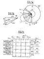
- FIGS. 1a, 1b, 1c showing on the one hand how are distributed the information on the surface of a magnetic recording medium such as a magnetic disc, according to the prior art (FIG. 1a and FIG. 1b) and on the other hand some reminders illustrated by FIG. 1c showing how the information is distributed within the reference zones, according to this same prior art.
- FIGS. 1a to 1c it is assumed that information is written in the reference areas of a magnetic disc DISC.
- this disc DISC rotates in the direction of the arrow F. Its useful recording surface is delimited by the circles d1, d2.
- each sector S i is divided into two parts SDO i , SAD i where the data to be processed are respectively recorded, on the one hand, and the information of address and fine position.
- the surface of the SAD i part is much smaller than the surface of the SDO i part (a few percent).
- N ′ (N + 1) reference zones ZRP i0 , ..., ZRP ij , ... ZRP i (N) , N being the total number of DISC disc recording tracks.
- N the total number of DISC disc recording tracks.
- FIG. 1c shows more precisely the nature of the information contained in each reference zone ZRP ij , and how this information is distributed within the zone (according to the aforementioned patent 2,439,435).
- the reference area ZRP ij comprises three parts PPA ij , PAD ij , PPOS ij each comprising an identical number of binary information (for example ten) each contained in an information cell.
- the first part called PPA ij includes the preamble information (defined above).
- the PAD part ij includes a certain number of information defining the absolute address of the track (this number is of course a function of the total number of tracks contained on the disc).
- the PPOS part ij includes a certain number of fine position information making it possible to keep the read transducer associated with the disc DISC perfectly centered above the track with sequence number j, opposite which it is located. This allows greater accuracy in reading the data from the transducer.
- Each binary information can be constituted either by a simple magnetic transition, or by a double magnetic transition.
- the mode of detection of the reference area using the first or even the second magnetic transition of the first part PPA ij proves to be insufficient.
- the mode of writing information inside the reference zones according to the invention makes it possible to avoid this drawback and is particularly well suited to be used in the dicos of magnetooptical memories called magnetooptic disks for simplicity. It will therefore be assumed subsequently that the DISC disk is magnetooptical.
- each binary item of information is constituted by a magnetic domain of magnetization, either positive or negative.
- the value of each information is a function of the sign of the magnetization in each domain (the latter therefore constitutes a cell containing binary information).
- a positive magnetization domain corresponds to binary information equal to 1 logic
- a negative magnetization corresponds to binary information equal to 1 logic.
- the binary information is no longer constituted by magnetic transitions, but is constituted directly by the sign of the magnetization inside each elementary magnetic domain.
- the subgroup of information ZCA ij contains six pairs of bits equal to 1 and 0.
- the latter therefore consists of a sequence of 1 and 0, that is to say a sequence of six couples constituted by a magnetic domain of positive magnetization followed by a magnetic domain with negative magnetization.
- the first part is such that the magnetic domains which constitute it have substantially the same width as the data track of order number j and have the same medium.
- the circle which constitutes the middle of the track of order number j is merged with the circle which constitutes the middle of the first part of the reference area GCP ij . It is also said that this first part of the reference zone ZRP ij is centered "full track”.
- each second GDP ij part is offset by a width equal to that of a half-track with respect to the tracks of order number j, which means that the border between two second GDP ij parts, and GDP i (j + 1) , or between GDP ij and GDP i (j - 1) is confused respectively with the middle of track j and the middle of track (j - 1).
- the subgroup of synchronization information ZSY ij consists of a pseudo-random binary sequence, that is to say, of finite length, that is to say say comprising a finite number of bits, the detection of this binary sequence being carried out by correlation between on the one hand a reference sequence identical to the said binary sequence and stored in the circuits for managing the magneto-optical disc memory containing the disc DISC and on the other hand the sequence of bits ZSY ij read by the optical device for reading the magnetooptical disk memory.
- the detection by correlation is carried out by calculating the following autocorrelation function ⁇ XX ( ⁇ ), with: where T is the integration time.
- x (t) is the function corresponding to the reference sequence and x (t + ⁇ ) is the function corresponding to the sequence read by the optical reading device when it is opposite a subgroup of synchronization information ZSY ij .
- ⁇ is the time offset between the two functions x (t) and x (t + ⁇ ), with x (t) or x (t + ⁇ ) ⁇ ⁇ - 1; + 1 ⁇
- This autocorrelation function is equal to 1 if the time shift ⁇ is zero and close to 0 if ⁇ is different from 0.
- the subgroup of synchronization information ZSY ij constituted by the sequence written above is represented in FIG. 4a, it comprises a succession of magnetic domains D1, D2, .......... to D8.
- the domains D1, D3, D5, D7 have a positive magnetization, while the domains D2, D4, D6, D8 have negative magnetizations.
- the domain D1 of positive magnetization has a length equal to 4L while the domain D3 has a length equal to L, the domain D5 has a length equal to 2L and the domain D7 to a length equal to L.
- the magnetic domains of negative magnetization D2, D4, D6 and D8 have respectively lengths equal to L, L, 2L, 3L.
- this function is equal to 1 logic between the instants ⁇ 1 and ⁇ 2 (which corresponds to the reading time of the magnetic domain D1), between the instants ⁇ 3 and the instants ⁇ 4 (reading of the domain D3, ), between instants ⁇ 5 and ⁇ 6 (reading of domain D5), between instants ⁇ 7 and ⁇ 8 (reading of domain D7).
- the function x (t + ⁇ ) is equal to the logical 0 between the instants ⁇ 2 and ⁇ 3 (reading of the magnetic domain D2) between the instants ⁇ 4 and ⁇ 5 (reading of the domain D4), between the instants ⁇ 6 and ⁇ 7 (reading of the domain D6 ), and from time ⁇ 8 to time ⁇ 9 which represents the time when the reading of the sequence stops.
- a sampling clock (contained in the circuits for managing the magnetooptical memory) is used whose period T0 is less than the period T nom , the latter being also called bit period.
- the sampling of this binary sequence of synchronization information is carried out from an initial instant t i (see FIG. 7) which is located in the time interval when the optical device for reading the magneto-optical memory becomes located next to the white zone ZBL ij .
- a clock H S called "servo" clock whose period is equal to the bit period, ie T name is triggered, immediately after time t d , within a time interval not exceeding 0.5 T nom .
- This servo clock is of course of known type and is contained in said management circuits (see FIG. 7).
- the signal S for reading a determined transition from a reference area ZRP ij has a shape which varies from one area to another and which depends on the one hand on the manner which has been written the magnetic transition between the two successive magnetic domains that surround it, and on the other hand the way it is read.
- This signal therefore has a waveform which varies between the form S1 and the form S2 shown in FIG. 6.
- the signal S has a substantially trapezoidal shape.
- t1 is also the instant when S2 has an amplitude equal to 10% of the peak-to-peak amplitude and that t6 is the instant when S1 has an amplitude equal to 90% of the peak-to-peak amplitude (although this is not, of course, strictly exact, we consider that this is true with a sufficient approximation).
- BC A ⁇ C - A ⁇ B
- a ⁇ C and A ⁇ B are the maximum and minimum descent times respectively.
- the signals S1 and S2 being practically symmetrical (isosceles trapezoids),
- a ⁇ C and A ⁇ B are also the maximum and minimum rise times and are designated by t m (max) and t m (min) , we have:
- T min T nom - ⁇ t m / 2 (12)
- T max T nom + ⁇ t m / 2 (13)
- T nT0, (T0: sampling period) and n positive integer.
- bit period T nom is equal to T0 X (2 k + 1) / 2 with k being able to take the values 1, 2, 3, etc.
- the bit period can take the values 75, 125, 175, 225, etc. ... nano-seconds.
- bit period T nom is equal to an odd multiple of the synchronization half-sampling period T0.
- a value of k equal to 4 is preferably chosen, which gives a bit period T nom of 225 nanoseconds and allows the start of the reference zone to be determined with sufficient precision. , that is to say, the instant t d as shown in FIG. 7.
- different waveforms have been represented corresponding to the signals read by the optical reading device when the latter is in succession facing the synchronization subgroups ZSY ij and the preamble ZCA ij and the address group ZAD ij .
Landscapes
- Engineering & Computer Science (AREA)
- Signal Processing (AREA)
- Signal Processing For Digital Recording And Reproducing (AREA)
Applications Claiming Priority (2)
| Application Number | Priority Date | Filing Date | Title |
|---|---|---|---|
| FR8707515A FR2615998A1 (fr) | 1987-05-27 | 1987-05-27 | Mode d'ecriture d'informations de synchronisation sur un support d'enregistrement magnetique |
| FR8707515 | 1987-05-27 |
Publications (2)
| Publication Number | Publication Date |
|---|---|
| EP0295164A1 true EP0295164A1 (de) | 1988-12-14 |
| EP0295164B1 EP0295164B1 (de) | 1991-10-09 |
Family
ID=9351536
Family Applications (1)
| Application Number | Title | Priority Date | Filing Date |
|---|---|---|---|
| EP88401246A Expired - Lifetime EP0295164B1 (de) | 1987-05-27 | 1988-05-20 | Verfahren zum Schreiben von Synchronisierungsinformation auf einen magnetischen Augzeichnungsträger |
Country Status (5)
| Country | Link |
|---|---|
| US (1) | US4831465A (de) |
| EP (1) | EP0295164B1 (de) |
| JP (1) | JPH0648580B2 (de) |
| DE (1) | DE3865369D1 (de) |
| FR (1) | FR2615998A1 (de) |
Families Citing this family (2)
| Publication number | Priority date | Publication date | Assignee | Title |
|---|---|---|---|---|
| US5272691A (en) * | 1991-05-30 | 1993-12-21 | Matsushita Electric Industrial Co., Ltd. | Method for recording and reproducing compressed data |
| US6995938B2 (en) * | 2004-05-06 | 2006-02-07 | Hitachi Global Storage Technologies Netherlands B.V. | Data recording system with servo pattern having pseudo-noise sequences |
Citations (5)
| Publication number | Priority date | Publication date | Assignee | Title |
|---|---|---|---|---|
| GB1307451A (en) * | 1971-06-10 | 1973-02-21 | Mullard Ltd | Information transmission synchronization systems |
| EP0013326A2 (de) * | 1978-12-27 | 1980-07-23 | International Business Machines Corporation | Servo-Lageregelungssystem mit abgetasteten Positionswerten und seine Anwendung in einem Plattenspeicher mit Servo-Sektoren |
| EP0130248A1 (de) * | 1983-06-30 | 1985-01-09 | International Business Machines Corporation | Spurnachlaufservosystem für eine Magnetplattenvorrichtung |
| EP0159720A2 (de) * | 1984-04-27 | 1985-10-30 | Sony Corporation | Kommunikationssystem für bidirektionale Digitalsignale |
| US4669003A (en) * | 1986-05-02 | 1987-05-26 | Hewlett-Packard Company | Method and apparatus for eliminating apparent offset in the servo code in a magnetic disc drive |
Family Cites Families (2)
| Publication number | Priority date | Publication date | Assignee | Title |
|---|---|---|---|---|
| US3952329A (en) * | 1975-02-06 | 1976-04-20 | International Business Machines Corporation | Pulse compression recording |
| FR2346806A1 (fr) * | 1976-03-31 | 1977-10-28 | Honeywell Bull Soc Ind | Mode d'ecriture d'adresses sur un support d'enregist rement magnetique |
-
1987
- 1987-05-27 FR FR8707515A patent/FR2615998A1/fr not_active Withdrawn
-
1988
- 1988-05-20 DE DE8888401246T patent/DE3865369D1/de not_active Expired - Lifetime
- 1988-05-20 EP EP88401246A patent/EP0295164B1/de not_active Expired - Lifetime
- 1988-05-25 JP JP63128127A patent/JPH0648580B2/ja not_active Expired - Lifetime
- 1988-05-26 US US07/199,353 patent/US4831465A/en not_active Expired - Lifetime
Patent Citations (5)
| Publication number | Priority date | Publication date | Assignee | Title |
|---|---|---|---|---|
| GB1307451A (en) * | 1971-06-10 | 1973-02-21 | Mullard Ltd | Information transmission synchronization systems |
| EP0013326A2 (de) * | 1978-12-27 | 1980-07-23 | International Business Machines Corporation | Servo-Lageregelungssystem mit abgetasteten Positionswerten und seine Anwendung in einem Plattenspeicher mit Servo-Sektoren |
| EP0130248A1 (de) * | 1983-06-30 | 1985-01-09 | International Business Machines Corporation | Spurnachlaufservosystem für eine Magnetplattenvorrichtung |
| EP0159720A2 (de) * | 1984-04-27 | 1985-10-30 | Sony Corporation | Kommunikationssystem für bidirektionale Digitalsignale |
| US4669003A (en) * | 1986-05-02 | 1987-05-26 | Hewlett-Packard Company | Method and apparatus for eliminating apparent offset in the servo code in a magnetic disc drive |
Non-Patent Citations (2)
| Title |
|---|
| IEEE TRANSACTIONS ON MAGNETICS, vol. MAG-17, no. 4, juillet 1981, pages 1396-1402, IEEE, New York, US; C. MAURY: "High track density for magnetic disk drives with an "embedded servo" positioning system" * |
| NEUES AUS DER TECHNIK, no. 3, 15 juin 1979, page 4, Würzburg, DE; "Servospurkodierungsmuster" * |
Also Published As
| Publication number | Publication date |
|---|---|
| US4831465A (en) | 1989-05-16 |
| DE3865369D1 (de) | 1991-11-14 |
| JPS63306569A (ja) | 1988-12-14 |
| JPH0648580B2 (ja) | 1994-06-22 |
| EP0295164B1 (de) | 1991-10-09 |
| FR2615998A1 (fr) | 1988-12-02 |
Similar Documents
| Publication | Publication Date | Title |
|---|---|---|
| KR960000452B1 (ko) | 디스크 장치 및 디스크형 기록 매체 | |
| EP0090690B1 (de) | Verfahren und Anordnung zur Regenerierung der Phase der Synchronisationssignale in einem optischen Aufzeichnungswiedergabegerät für Informationsträger | |
| EP0138273B1 (de) | Gerät zur Wiedergabe von Informationen auf einem optisch lesbaren Informationsträger | |
| EP0010494A1 (de) | Verfahren zum Informationsschreiben auf einen magnetischen Aufzeichnungsträger | |
| US4811316A (en) | Apparatus for seeking a track of an optical information carrier in which a loss of detection signal is compensated for | |
| EP0133067B1 (de) | Verfahren und Anordnung zur Regenerierung von wiedergegebenen, auf einer optischen Platte aufgezeichneten Datensignalen | |
| EP0077693B1 (de) | Opto-elektronische Vorrichtung zum Auslesen der Information eines magnetischen Aufzeichnungsträgers | |
| EP0032324B1 (de) | Verfahren zur Verstärkungsregelung von Schaltungsanordnungen zum Verstärken von Signalen, die von einem Lesekopf abgegeben werden, der mit einem Informations-Aufzeichnungsträger gekoppelt ist, und Vorrichtung zur Ausführung des Verfahrens | |
| EP0148077B1 (de) | Verfahren zur Aufzeichnung von Informationen auf einem Aufzeichnungsträger | |
| EP0295979B1 (de) | Verfahren zur Aufzeichnung von Information auf einem magnetischen Aufzeichnungsträger | |
| EP0295164B1 (de) | Verfahren zum Schreiben von Synchronisierungsinformation auf einen magnetischen Augzeichnungsträger | |
| FR2668289A1 (fr) | Procede d'adressage de tetes elementaires d'une tete multipiste d'enregistrement sur support magnetique et tete magnetique le mettant en óoeuvre. | |
| EP0766863B1 (de) | Verfahren zum lesen von informationen | |
| JPH024065B2 (de) | ||
| FR2635401A1 (fr) | Procede d'enregistrement d'informations sur un support de type disque, support d'enregistrement d'informations enregistrees et dispositif d'enregistrement-lecture pour la mise en oeuvre du procede | |
| EP1196914B1 (de) | Spurfolgesystem zur aufzeichnung/wiedergabe eines informationsträgers und aufzeichnungsträger | |
| KR0176524B1 (ko) | 광 디스크 기록 매체 및 그 재생 방법 | |
| EP0064438A1 (de) | Aufzeichnungs-/Wiedergabeanordnung, die einen beweglichen Informationsträger mit einer vorgeprägten Spur enthält | |
| JPS61107539A (ja) | 光学デイスク装置 | |
| JPS6353777A (ja) | デイスク状記録媒体 | |
| FR2779863A1 (fr) | Systeme de suivi de piste pour l'enregistrement/lecture d'un support d'informations et support d'enregistrement | |
| RU2316060C1 (ru) | Накопитель информации на оптическом диске | |
| JPH0770149B2 (ja) | デイスク装置 | |
| JPH027232A (ja) | 光学的情報記録再生装置 | |
| FR2772505A1 (fr) | Procede et dispositif de synchronisation et de rephasage d'horloges d'un lecteur-enregistreur de disque optique et disque optique associe |
Legal Events
| Date | Code | Title | Description |
|---|---|---|---|
| PUAI | Public reference made under article 153(3) epc to a published international application that has entered the european phase |
Free format text: ORIGINAL CODE: 0009012 |
|
| AK | Designated contracting states |
Kind code of ref document: A1 Designated state(s): DE FR GB IT NL |
|
| 17P | Request for examination filed |
Effective date: 19890107 |
|
| 17Q | First examination report despatched |
Effective date: 19910131 |
|
| GRAA | (expected) grant |
Free format text: ORIGINAL CODE: 0009210 |
|
| AK | Designated contracting states |
Kind code of ref document: B1 Designated state(s): DE FR GB IT NL |
|
| GBT | Gb: translation of ep patent filed (gb section 77(6)(a)/1977) | ||
| REF | Corresponds to: |
Ref document number: 3865369 Country of ref document: DE Date of ref document: 19911114 |
|
| ITF | It: translation for a ep patent filed | ||
| PLBE | No opposition filed within time limit |
Free format text: ORIGINAL CODE: 0009261 |
|
| STAA | Information on the status of an ep patent application or granted ep patent |
Free format text: STATUS: NO OPPOSITION FILED WITHIN TIME LIMIT |
|
| 26N | No opposition filed | ||
| REG | Reference to a national code |
Ref country code: GB Ref legal event code: IF02 |
|
| PGFP | Annual fee paid to national office [announced via postgrant information from national office to epo] |
Ref country code: DE Payment date: 20040423 Year of fee payment: 17 |
|
| PGFP | Annual fee paid to national office [announced via postgrant information from national office to epo] |
Ref country code: GB Payment date: 20050427 Year of fee payment: 18 |
|
| PGFP | Annual fee paid to national office [announced via postgrant information from national office to epo] |
Ref country code: FR Payment date: 20050530 Year of fee payment: 18 |
|
| PG25 | Lapsed in a contracting state [announced via postgrant information from national office to epo] |
Ref country code: DE Free format text: LAPSE BECAUSE OF NON-PAYMENT OF DUE FEES Effective date: 20051201 |
|
| PGFP | Annual fee paid to national office [announced via postgrant information from national office to epo] |
Ref country code: NL Payment date: 20060425 Year of fee payment: 19 |
|
| PG25 | Lapsed in a contracting state [announced via postgrant information from national office to epo] |
Ref country code: GB Free format text: LAPSE BECAUSE OF NON-PAYMENT OF DUE FEES Effective date: 20060520 |
|
| PGFP | Annual fee paid to national office [announced via postgrant information from national office to epo] |
Ref country code: IT Payment date: 20060531 Year of fee payment: 19 |
|
| GBPC | Gb: european patent ceased through non-payment of renewal fee |
Effective date: 20060520 |
|
| REG | Reference to a national code |
Ref country code: FR Ref legal event code: ST Effective date: 20070131 |
|
| PG25 | Lapsed in a contracting state [announced via postgrant information from national office to epo] |
Ref country code: NL Free format text: LAPSE BECAUSE OF NON-PAYMENT OF DUE FEES Effective date: 20071201 |
|
| NLV4 | Nl: lapsed or anulled due to non-payment of the annual fee |
Effective date: 20071201 |
|
| PG25 | Lapsed in a contracting state [announced via postgrant information from national office to epo] |
Ref country code: FR Free format text: LAPSE BECAUSE OF NON-PAYMENT OF DUE FEES Effective date: 20060531 |
|
| PG25 | Lapsed in a contracting state [announced via postgrant information from national office to epo] |
Ref country code: IT Free format text: LAPSE BECAUSE OF NON-PAYMENT OF DUE FEES Effective date: 20070520 |