EP0295374A2 - Vorrichtung und Verfahren zum Schneiden von optischen Fasern - Google Patents
Vorrichtung und Verfahren zum Schneiden von optischen Fasern Download PDFInfo
- Publication number
- EP0295374A2 EP0295374A2 EP88105121A EP88105121A EP0295374A2 EP 0295374 A2 EP0295374 A2 EP 0295374A2 EP 88105121 A EP88105121 A EP 88105121A EP 88105121 A EP88105121 A EP 88105121A EP 0295374 A2 EP0295374 A2 EP 0295374A2
- Authority
- EP
- European Patent Office
- Prior art keywords
- optical fiber
- clamps
- cutting apparatus
- score
- fiber
- Prior art date
- Legal status (The legal status is an assumption and is not a legal conclusion. Google has not performed a legal analysis and makes no representation as to the accuracy of the status listed.)
- Granted
Links
Images


Classifications
-
- G—PHYSICS
- G02—OPTICS
- G02B—OPTICAL ELEMENTS, SYSTEMS OR APPARATUS
- G02B6/00—Light guides; Structural details of arrangements comprising light guides and other optical elements, e.g. couplings
- G02B6/24—Coupling light guides
- G02B6/25—Preparing the ends of light guides for coupling, e.g. cutting
-
- G—PHYSICS
- G02—OPTICS
- G02B—OPTICAL ELEMENTS, SYSTEMS OR APPARATUS
- G02B6/00—Light guides; Structural details of arrangements comprising light guides and other optical elements, e.g. couplings
- G02B6/24—Coupling light guides
- G02B6/36—Mechanical coupling means
- G02B6/3616—Holders, macro size fixtures for mechanically holding or positioning fibres, e.g. on an optical bench
-
- G—PHYSICS
- G02—OPTICS
- G02B—OPTICAL ELEMENTS, SYSTEMS OR APPARATUS
- G02B6/00—Light guides; Structural details of arrangements comprising light guides and other optical elements, e.g. couplings
- G02B6/24—Coupling light guides
- G02B6/36—Mechanical coupling means
- G02B6/3628—Mechanical coupling means for mounting fibres to supporting carriers
- G02B6/3632—Mechanical coupling means for mounting fibres to supporting carriers characterised by the cross-sectional shape of the mechanical coupling means
- G02B6/3636—Mechanical coupling means for mounting fibres to supporting carriers characterised by the cross-sectional shape of the mechanical coupling means the mechanical coupling means being grooves
-
- Y—GENERAL TAGGING OF NEW TECHNOLOGICAL DEVELOPMENTS; GENERAL TAGGING OF CROSS-SECTIONAL TECHNOLOGIES SPANNING OVER SEVERAL SECTIONS OF THE IPC; TECHNICAL SUBJECTS COVERED BY FORMER USPC CROSS-REFERENCE ART COLLECTIONS [XRACs] AND DIGESTS
- Y10—TECHNICAL SUBJECTS COVERED BY FORMER USPC
- Y10T—TECHNICAL SUBJECTS COVERED BY FORMER US CLASSIFICATION
- Y10T225/00—Severing by tearing or breaking
- Y10T225/10—Methods
- Y10T225/12—With preliminary weakening
-
- Y—GENERAL TAGGING OF NEW TECHNOLOGICAL DEVELOPMENTS; GENERAL TAGGING OF CROSS-SECTIONAL TECHNOLOGIES SPANNING OVER SEVERAL SECTIONS OF THE IPC; TECHNICAL SUBJECTS COVERED BY FORMER USPC CROSS-REFERENCE ART COLLECTIONS [XRACs] AND DIGESTS
- Y10—TECHNICAL SUBJECTS COVERED BY FORMER USPC
- Y10T—TECHNICAL SUBJECTS COVERED BY FORMER US CLASSIFICATION
- Y10T225/00—Severing by tearing or breaking
- Y10T225/30—Breaking or tearing apparatus
- Y10T225/307—Combined with preliminary weakener or with nonbreaking cutter
- Y10T225/321—Preliminary weakener
- Y10T225/325—With means to apply moment of force to weakened work
-
- Y—GENERAL TAGGING OF NEW TECHNOLOGICAL DEVELOPMENTS; GENERAL TAGGING OF CROSS-SECTIONAL TECHNOLOGIES SPANNING OVER SEVERAL SECTIONS OF THE IPC; TECHNICAL SUBJECTS COVERED BY FORMER USPC CROSS-REFERENCE ART COLLECTIONS [XRACs] AND DIGESTS
- Y10—TECHNICAL SUBJECTS COVERED BY FORMER USPC
- Y10T—TECHNICAL SUBJECTS COVERED BY FORMER US CLASSIFICATION
- Y10T225/00—Severing by tearing or breaking
- Y10T225/30—Breaking or tearing apparatus
- Y10T225/371—Movable breaking tool
- Y10T225/379—Breaking tool intermediate spaced work supports
- Y10T225/386—Clamping supports
Definitions
- the present invention relates to a method and an apparatus for cutting an optical fiber.
- each optical fiber In order to properly join a pair of optical fibers, it is necessary that the surface of the connecting end of each fiber be flat and perpendicular to the fiber's axis. To provide such an end face, the distal end of each optical fiber needs to be properly cut prior to splicing the fibers. Conventionally, this fiber cutting has been done using a fiber cutting apparatus as shown in Figs. 1A to 1C.
- Fig. 1A illustrates an example of a conventional optical fiber cutting apparatus applicable to single-core fibers.
- Reference numeral 10 denotes a first clamp, which comprises a clamp table 12 and a pincher 14.
- Pincher 14 is freely openable and closable to clamp table 12, and, when closed, it clamps a sheathed portion 42 of an optical fiber 40.
- Reference numeral 16 denotes a rubber member used to absorb the stress applied on sheathed portion 42 by pincher 14.
- pincher 14 is illustrated to move vertically with respect to clamp table 12. Actually, however, pincher 14 is often attached to clamp table 12 by means of a hinge 18 so as to be rockable to the clamp table, as shown in Fig. 2.
- the former design of first clamp 10 (see Figs. 1A-1C) is the same as the latter design (Fig. 2) in principle and is easier to see its operation.
- a second clamp 20 is also illustrated in the same manner so that its pincher 24 is shown to move vertically with respect to a clamp table 22.
- Second clamp 20 comprises clamp table 22 and pincher 24.
- Pincher 24 is freely openable and closable to clamp table 22, and, when closed, it clamps an unsheathed or bare portion 44 (i.e., glass portion) of an optical fiber 40.
- Reference numeral 26 denotes a rubber member used to absorb the stress applied on glass portion 44 by pincher 24.
- Reference numeral 50 is a base for supporting clamp tables 12 and 22.
- Reference numeral 52 is a scoring blade provided between first clamp 10 and second clamp 20, which moves within a plane perpendicular to the axis of optical fiber 40 in the horizontal or arched direction and scores the optical fiber at the desired portion.
- Reference numeral 54 is a pushing member which applies bending stress on the scored optical fiber 40 from the opposite side of the score to cut the fiber.
- optical fiber 40 is placed on clamp tables 12 and 22, as shown in Fig. 1A, then first clamp 10 is closed (Fig. 1B), and finally, second clamp 20 is closed (Fig. 1C). Thereafter, scoring blade 52 is moved within a plane perpendicular to the axis of optical fiber 40 in the horizontal direction or the arched direction, to score the optical fiber at the desired portion. Then, pushing member 54 applies bending stress on the scored optical fiber 40 from the opposite side of the score to cut the fiber.
- Fig. 3 illustrates the cutting apparatus, applied to a single core fiber, in a different aspect.
- the same reference numerals as are used in Figs. 1A-1C are also used to specify the corresponding sections, thus omitting their otherwise redundant explanation.
- Reference numeral 62 is a third clamp.
- Scoring blade 52 is provided between second clamp 20 and third clamp 62 and is movable in the horizontal direction or in the arched direction, to score bare fiber 44 at the desired portion.
- the score on the optical fiber should also be perpendicular to the fiber axis 88.
- optical fiber 40 needs to be clamped perpendicular to the moving direction 90 of scoring blade 52.
- sheathed portion 42 of optical fiber 40 is normally rolled and naturally curvy, so that the optical fiber even clamped may not be held straight as shown in Fig. 3. Therefore, the moving direction of scoring blade 52 is not perpendicular to the axis 88 of optical fiber 40 and the score would not be perpendicular to the fiber axis accordingly.
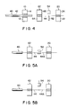
- Fig. 4 illustrates the cutting apparatus, applied to a single core fiber, in another aspect.
- Figs. 4, 5A and 5B the same reference numerals as are used in the previously-described diagrams are also used to specify the corresponding sections, thus omitting their otherwise redundant explanation.
- Third clamp 62 comprises a clamp table 64 and pincher 66.
- Pincher 66 is freely openable and closable to clamp table 64, and, when closed, it clamps bare portion (i.e., glass portion) 44 of an optical fiber 40.
- Reference numeral 36 is a rubber member used to absorb the stress applied on glass portion 44 by pincher 66.
- Scoring blade 52 is moved in the horizontal direction or in the arched direction, to score bare fiber 44 at the desired portion, and then pushing member 54 is pressed against bare fiber 44, the fiber is cut (Fig. 5A). Pushing member 54 is then retracted (Fig. 5B), releasing the stress on the cut portions of bare fiber 44, so that the cut end of the fiber 44 and the end of a waste bare fiber 44A are likely to hit against each other. This may chip off or make a crack on the end face of bare fiber 44.
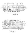
- Figs. 6 and 7 illustrate the cutting apparatus, applied to a single core fiber, in a still different aspect.
- the same reference numerals as are used in the previously-described diagrams are also used to specify the corresponding sections, thus omitting their otherwise redundant explanation.
- Reference numeral 92 is a base of the overall cutting apparatus, and numeral 94 is a set table.
- sheathed portion 42 does not have a tendency to be curvy so that groove 82 is sufficient and it is unnecessary to form slit 84 in second guide 80. Sheathed portion 42 can freely be move within grooves 76 and 82.
- Reference numeral 96 is a scale on which the end face of the fiber to be cut is aligned so as to determine the cutting length L.
- a stationary jig is mounted to optical fiber 40.
- Another object of the invention is to provide an optical fiber cutting apparatus, in which the fiber is cut in a direction perpendicular to the axis thereof even if the fiber is curvy.
- a further object of the present invention is to provide an optical fiber cutting apparatus, in which the cut ends of the fiber are prevented from being hitting after the cutting of the fiber.
- a still further object of the present invention is to provide an optical fiber cutting apparatus which can be applied to different types of the optical fibers.
- a yet further object of the present invention is to provide a method of cutting an optical fiber, in which the cut ends of the fiber are prevented from being hitting after the cutting of the fiber.
- an optical fiber cutting apparatus which comprises: a plurality of clamps for clamping an optical fiber set straight, each of the clamps comprising a pincher and a table, the pinchers of predetermined two adjacent clamps of the plurality of clamps being formed integrally; a scoring blade, provided between the predetermined two adjacent clamps, for making a score on the optical fiber by moving within a plane substantially perpendicular to the optical fiber; and a pushing member for pushing the optical fiber from an opposite side of the score to cut the optical fiber.
- an optical fiber cutting apparatus which comprises: a plurality of clamps for clamping an optical fiber set straight, each of the clamps comprising a pincher and a table; a scoring blade, provided between predetermined two adjacent clamps of the plurality of clamps, for making a score on the optical fiber by moving within a plane substantially perpendicular to the optical fiber; a pushing member for pushing the optical fiber from an opposite side of the score to cut the optical fiber; and at least one reference straight line means provided at a location under the optical fiber to be clamped by the clamps, in a direction substantially perpendicular to a moving direction of the scoring blade.
- an optical fiber cutting apparatus which comprises: a plurality of clamps for clamping an optical fiber set straight, each of the clamps comprising a pincher and a table; a scoring blade, provided between predetermined two adjacent clamps of the plurality of clamps, for making a score on the optical fiber by moving within a plane substantially perpendicular to the optical fiber; and a pushing member for pushing the optical fiber from an opposite side of the score to cut the optical fiber, the pushing member being retracted after the optical fiber cut by the pushing member is rendered movable by releasing the predetermined two adjacent clamps while the optical fiber is still being bent by the pushing member.
- an optical fiber cutting apparatus comprising; a main body comprising a plurality of clamps for clamping an optical fiber set straight, a scoring blade, provided between predetermined two adjacent clamps of said plurality of clamps, for making a score on said optical fiber, a pushing member for pushing said optical fiber from an opposite side of said score to cut said optical fiber, a base on which said plurality of clamps, said scoring blade and said pushing member are provided at predetermined positions, and a set table provided on a straight alignment line of said plurality of clamps on a side of an outermost one of said plurality of clamps and having a guide groove formed on a top surface thereof; and an adapter comprising a plate having first and second guides formed in accordance with a type of an optical fiber to be cut, and detachably fitable in said guide groove.
- an optical fiber cutting apparatus comprising; a main body comprising a plurality of clamps for clamping an optical fiber set straight, a scoring blade, provided between predetermined two adjacent clamps of said plurality of clamps, for making a score on said optical fiber, a pushing member for pushing said optical fiber from an opposite side of said score to cut said optical fiber, a base on which said plurality of clamps, said scoring blade and said pushing member are provided at predetermined positions, and a set table provided on a straight alignment line of said plurality of clamps on a side of an outermost one of said plurality of clamps and having a guide groove formed on a top surface thereof, an adapter comprising a plate having first and second guides formed in accordance with a type of an optical fiber to be cut, and detachably fitable in said guide groove; and a stationary jig comprising a plate and a lid, for securing a multicore optical fiber therebetween, the sizes of said plate of said
- a method for cutting an optical fiber comprising the steps of: causing a plurality of clamps to clamp an optical fiber set straight; moving a scoring blade between predetermined two adjacent clamps of the plurality of clamps to make a score on the optical fiber; causing a pushing member to push the optical fiber from an opposite side of the score to cut the optical fiber; and retracting the pushing member after the optical fiber cut by the pushing member is rendered movable by releasing the predetermined two adjacent clamps while the optical fiber is still being bent by the pushing member.
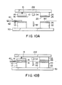
- Figs. 10A and 10B schematically illustrate an optical fiber cutting apparatus according to an embodiment of this invention.
- Reference numeral 10 denotes a first clamp, which comprises a clamp table 12 and a pincher 14.
- Pincher 14 is freely openable and closable to clamp table 12, and, when closed, it clamps a sheathed portion 42 of an optical fiber 40.
- Reference numeral 16 denotes a rubber member used to absorb the stress applied on sheathed portion 42 by pincher 14.
- pincher 14 is illustrated to move vertically with respect to clamp table 12. Actually, however, pincher 14 is attached to clamp table 12 by means of a hinge (not shown) so as to be rockable to the clamp table.
- the former design of first clamp 10 (see Figs. 10A and 10B) is the same as the latter design in principle and is easier to see its operation.
- a second clamp 24 is also illustrativelyed in the same manner so that its pincher 24 is shown to move vertically with respect to a clamp table 22.
- Second clamp 20 comprises clamp table 22 and pincher 24.
- Pincher 24 is freely openable and closable to clamp table 22, and, when closed, it clamps an unsheathed or bare portion 44 (i.e., glass portion) of an optical fiber 40.
- Reference numeral 26 denotes member used to absorb the stress applied on glass portion 44 by pincher 24.
- Reference numeral 50 is a base for supporting clamp tables 12 and 22.
- Reference numeral 52 is a scoring blade provided between first clamp 10 and second clamp 20, which moves within a plane perpendicular to the axis of optical fiber 40 in the horizontal direction or the arched direction and scores the optical fiber at the desired portion.
- Reference numeral 54 is a pushing member which applies bending stress on the scored optical fiber 40 from the opposite side of the score to cut the fiber.
- Pincher 14 of clamp 10 is attached to a plate 212 by means of a spring 15, while pincher 24 of clamp 20 is directly mounted on plate 212. Pinchers 14 and 24 move integrally. That is, the cutting apparatus of this embodiment is designed such that pinchers 14 and 24 of clamps 10 and 20 provided on the respective sides of the fiber cutting section are made integral by plate 212. This is the difference between the cutting apparatus of this embodiment and the conventional cutting apparatus as shown in Figs. 1A-1C.
- first clamp 10 and second clamp 20 are released and optical fiber 40 is placed on clamp tables 12 and 22, as shown in Fig. 10A.
- pinchers 14 and 24 made integral by plate 212 are simultaneously closed to clamp optical fiber 40 at the same time.
- scoring blade 52 is moved within a plane perpendicular to the axis of optical fiber 40 in the horizontal direction or the arched direction, to score the optical fiber at the desired portion.
- pushing member 54 applies bending stress on the scored optical fiber 40 from the opposite side of the score to cut the fiber.
- Figs. 11A to 11C illustrate another embodiment which further has a third clamp 62 in addition to first and second clamps 10 and 20, and first fiber guide 72 and second fiber guide 80.
- Third clamp 62 comprises a clamp table 64 and pincher 66.
- Pincher 66 is freely openable and closable to clamp table 64, and, when closed, it clamps bare portion 44 of an optical fiber 40.
- Reference numeral 36 is a rubber member used to absorb the stress applied on glass portion 44 by pincher 66.
- clamps 10, 20 and 62 are integrally formed. However, clamp 10 may be separate from clamps 20 and 62 which sandwich the fiber portion to be cut.
- Reference numeral 72 is a first guide, which is provided on the rear side (on the side of sheathed portion 42) of first clamp 10 (see the arrow 74 in Fig. 11A for the rear and front side) and has a groove 76 provided to receive sheathed portion 42, as shown in the lower left cross section in Fig. 11A.
- Reference numeral 80 is a second guide provided on the front side (on the side of bare fiber 44) of first clamp 10, and the second guide 80 has a groove 82 provided to receive sheathed portion 42 and a slit 84 to receive bare fiber 44, as shown in the lower left and right cross sections in Fig. 11A.
- the groove 82 and slit 84 are formed to be continuous to each other.
- the cutting apparatus of Figs. 11A to 11C may be applied to cutting a taped multicore fiber.
- a stationary jig is attached to optical fiber 40 and is clamped by first clamp 10, and scoring blade 52 is moved horizontally in a plane perpendicular to the axis of the fiber, to score the bare fiber portion.
- Optical fiber 40 is set such that its sheathed portion 42 is fit in groove 76 of guide 72 and groove 82 of guide 80 and its glass portion 44 is fit in slit 84 of guide 80.
- plate 212 is moved downward, thus causing pincher 14 of first clamp 10 to contact sheathed potion 42 of optical fiber 40 to thereby clamp the fiber in the direction perpendicular to the moving direction of scoring blade 52.
- Plate 212 is moved further down, causing second and third clamps 20 and 66 to simultaneously clamp optical fiber 40. Consequently, optical fiber 40 can be properly scored by scoring blade 52.
- Each of the first and second embodiments can be applied to both of single core and multicore optical fibers.
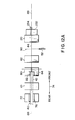
- Figs. 12A and 12B illustrate an optical fiber cutting apparatus applied to cutting a single core fiber, according to a further embodiment of this invention.
- at least one reference straight light is provided in the direction perpendicular to the moving direction of the scoring blade 52, at the location on which the optical fiber is to be set and clamped for its proper alignment. Consequently, even though the optical fiber is curvy, the fiber can be properly set on a predetermined line.
- Second clamp 20 may be integrated with third clamp 62.
- all clamps 10, 20 and 62 may be integrated with one another.
- a plate 232 is provided on the front side of the foremost clamp 20 and has reference straight lines 234 provided on its top. As shown in Fig. 12B, the top of plate 232 is located lower than the top of table 22 of clamp 20.
- the straight lines 234 are provided in parallel to the center line 88 or perpendicular to the moving direction 90 of scoring blade 52.
- the number of the straight lines is, for example, 5 (e.g., 1 mm intervals between the lines) and the center one of the straight lines is aligned with the center line 88.
- Guide 80 is made horizontally movable within a plane perpendicular to the center line 88.
- Optical fiber 40 is set on the individual tables 12, 64 and 22 of the respective clamps 10, 62 and 20, and clamp 10 is first closed to clamp sheathed portion 42.
- guide 80 is slightly moved to align bare fiber 44 with the center one of straight lines 234 (i.e., the center line 88).
- clamps 62 and 20 are closed sequentially or simultaneously.
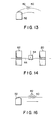
- scoring blade 52 is moved within a plane perpendicular to the axis of optical fiber 40 in the horizontal direction or the arched direction (Fig. 13), to score the optical fiber at the desired portion.
- pushing member 54 applies bending stress on the scored optical fiber 40 from the opposite side of the score to cut the fiber (Fig. 14).
- a correction guide 242 is provided at that portion slightly projecting from the distal end of stationary jig 240 toward bare fiber 44, as shown in Fig. 15.
- Guide 242 has a groove 244 for receiving sheathed portion 42, as shown in the lower cross sectional diagram in the figure, and is horizontally movable in the direction perpendicular to the center line 88.
- the optical fiber can be properly set on a predetermined line even if the fiber is curvy. This can ensure that the optical fiber can be scored in the direction perpendicular to the fiber axis. In this case, scoring blade 52 is moved horizontally as shown in Fig. 16.
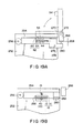
- Figs. 17A to 17D illustrate the optical fiber and the clamps in the individual steps of an optical fiber cutting method according to another embodiment of this invention.
- This method can easily prevent a score or crack from being made on the end face as a result that the cut ends of the optical fiber contact or hit against each other when these ends revert to the initial positions at which they are cut.
- Scoring blade 52 is moved in the direction perpendicular to the axis of bare fiber 44 to the optical fiber score at the desired portion (Fig. 17A).
- pushing member 54 is moved to push the scored portion of the fiber from the opposite side of scoring blade 52 to cut the fiber (Fig. 17B).
- pushing member 54 is retracted (Fig. 17D) to remove the optical fiber.
- the clamps on respective sides of the pushing member are slightly released so as to permit movement of the optical fiber, and the pushing member is then retracted to remove the optical fiber.
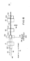
- FIG. 18 which is a plan view of the cutting apparatus with its lid fully open, reference numeral 252 is a main body of the cutting apparatus, and numeral 254 is a lid made openable and closable by means of a hinge 256.
- Figs. 19A and 19B respectively illustrate the cross sections of the cutting apparatus with its lid 254 closed, taken along lines A-A and B-B of Fig. 18, while Figs. 20A and 20B respectively illustrate the cross sections of the cutting apparatus with its lid 254 slightly open, taken along lines A-A and B-B of Fig. 18.
- Tables 64 and 22 of clamps 62 and 20 are mounted on apparatus body 252 and pinchers 66 and 24 are attached to lid 254.
- Table 12 of clamp 10 is mounted on apparatus body 252 and pincher 14 is attached to the apparatus body by means of a hinge 258 (Fig. 18).
- Reference numeral 260 is a magnet
- numeral 262 is a magnet-contact metal
- numeral 264 is a compression spring
- the clamping force of first clamp 10 is given by the force of spring 15 in addition to the attraction between magnet 260 and contact metal 262.
- Pushing member 54 is mounted as follows.
- An arm 266 is swingably mounted on one side of apparatus body 252 by means of a support shaft 268 provided at the proximity of one end of the arm.
- Another arm 270 extending in the direction perpendicular to the axis of arm 266 is liftably mounted at the proximity of the other end of arm 266, and pushing member 54 is mounted on the bottom of the distal end of arm 270.
- Scoring blade 52 is horizontally movable under arm 270.
- Reference numeral 274 is a lever, which is swingably mounted on apparatus body 252 by means of a pin 276 and has one end section 278 contacting the bottom of lid 254 and the other end section 280 facing arm 266 with a slight gap 268 between end section 280 and the bottom of arm 266.
- Pincher 14 is closed, lid 254 is closed and optical fiber 40 is clamped by clamps 10, 62 and 20.
- Scoring blade 52 is moved in the direction perpendicular to the axis of fiber 40 to score bare fiber 44.
- Arm 270 is lowered to push down pushing member 54, thereby cutting bare fiber 44 at the score.
- arms 270 and 266 are simultaneously lowered.
- arm 266 is lowered (Fig. 20A)
- its bottom contacts end section 280 of lever 274 to thereby lower the end section 280.
- the other end section 278 of lever 274 is moved up to lift up lid 254 against the attracting force of magnet 260, thereby slightly releasing clamps 62 and 20. Accordingly, bare fiber 44 and waste fiber 44A are permitted to be freely moved.
- lid 254 When lid 254 is slightly lifted up to separate magnet 260 from contact metal 262 a little, the magnetic force is reduced. Therefore, even the pushing of pushing member 54 is stopped, lid 254 is kept slightly open by the force of spring 15 (Fig. 20B) to thereby keep clamps 62 and 20 slightly open.
- bare fiber 44 and waste fiber 44A become straight due to their resilient force. Since clamps 62 and 20 are released at this time, bare fiber 44 does not hit against waste fiber 44A, thus preventing an undesirable score or crack from being made on the end face of the fiber. Even if bare fiber 44 and waste fiber 44A hit against each other, the collision is not strong enough (as bare fiber 44 and waste fiber 44A are not clamped at that time) to make any crucial damage.
- arm 270 is lifted up, lid 254 and pincher 14 are opened, and optical fiber 40 is removed.
- the clamps on respective sides of the pushing member are slightly released so as to permit movement of the optical fiber, and the pushing member is then retracted to remove the optical fiber. Therefore, the following effects are attained.
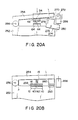
- Fig. 21A illustrates an optical fiber cutting apparatus according to a still another embodiment, which can be applied to cutting optical fibers with different sizes, types, cutting lengths, etc.
- This cutting apparatus differs from the conventional cutting apparatus shown in Figs. 1-9 in first guide 72, second guide 80 and the stationary jig. Clamps 66 and 20, scoring blade 52 and pushing member 54 are the same for both apparatuses.
- the overall cutting apparatus are constituted by a combination of:
- the desired adapter having the proper guides 72 and 80 can be selected and used in accordance with the size and shape of a single core fiber in use, so that the cutting apparatus can be applied to optical fibers with different sizes and shapes.
- table 22 of clamp 20 and table 64 of clamp 62 are provided on base 92.
- Set table 94 of a rectangular parallelepiped shape, for example, is provided at the rear side of these tables 22 and 64 and is formed with guide groove 282 on its top.
- Lid 254 is openably attached to set table 94 by hinge 256.
- Reference numeral 292 is a spring. Lid 254 is made to contact set table 94 by the attraction between magnet 260 provided on set table 94 and contact metal 262 provided on lid 254.
- Scoring blade 52 is mounted to a block 294 provided on base 92 and is horizontally moved as shown by the arrow 238, thereby scoring the bare fiber.
- scoring blade may be moved in the arched manner.
- Arm 266 is attached to the side of set table 94 substantially horizontally and is vertically swingable. Arm 274 liftable in the direction perpendicular to the axis of arm 266 is attached to the distal end of arm 266, and pushing member 54 is attached to the bottom of the distal end of arm 274. Compression spring 276 is provided between base 92 and arm 266.
- This adapter is used for a single core fiber whose sheathed portion has a relatively large diameter and a constant cutting length L (corresponding to the case as shown in Figs. 6 and 7).
- the adapter can be used when sheathed portion 42 has a diameter of 0.25-0.9 mm, for instance.
- Reference numeral 284 is a plate which has the same size as guide groove 282 and can detachably be fit in the groove 282.
- Plate 284 has first guide 72 and second guide 80 formed in its top surface.
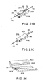
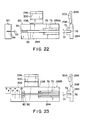
- Groove 76 of first guide 72 and groove 82 of second guide 80 have a width D1 of 1 mm, and slit 84 of second guide 80 has a width D2 of 0.13 mm (Fig. 22).
- Lid 296 is mounted to the side of plate 284 by hinge 298, and pushing rubber 300 is provided on the bottom of lid 296.
- This adapter is used for a single core fiber whose sheathed portion has a relatively small diameter and a variable cutting length L (corresponding to the case as shown in Fig. 8).
- the adapter can be used when sheathed portion 42 has a diameter of 0.25 mm and the cutting length L ranges between 6 to 20 mm, for instance.
- Groove 76 of first guide 72 and groove 82 of second guide 80 have a width D1 of 0.3 mm (Fig. 23).
- a scale 302 is integrally formed on plate 284.
- Sheathed portion 42 of optical fiber 40 is fit in grooves 76 and 82, bare fiber 44 is fit in slit 84, and lid 296 is closed (the optical fiber is not clamped yet in this state).
- adapter 286A is accommodated in guide groove 282 of apparatus body 252.
- the adapter should not necessarily be fixed to apparatus body 252 but may be fixed thereto by a screw.
- lid 296 of the adapter is pressed by spring 292 provided on lid 254 to securely clamp optical fiber 40.
- Sheathed portion 42 of optical fiber 40 is fit in grooves 76 and 82, and the end of the sheathed portion 42 is aligned with the figure of the cutting length L on scale 302.
- Adapter 286C is accommodated in guide groove 282 of apparatus body 252 and is secured thereto by a screw or the like as desired.
- Optical fiber 40 is then set on adapter 286C, and first clamp 10 mounted on apparatus body 252 is closed to clamp the fiber by the help of the attraction between magnet 260 provided on first clamp 10 and contact metal 262 provided on set table 94, for example.
- Optical fiber 40 may be clamped only by second and third clamps 20 and 62, without using first clamp 10.
- lid 296 of adapter 286D is designed to be able to sandwich optical fiber 40 by the help of the attraction between magnet 260 provided on plate 284 and contact 262 provided on lid 296.
- Reference numeral 300 denotes a rubber member used to absorb the stress applied on the optical fiber.
- Adapter 286D sandwiching optical fiber 40 is accommodated in guide groove 282 of apparatus body 252 and is fixed by closing first clamp 10.
- Optical fiber 40 may be clamped only by second and third clamps 66 and 20, without using first clamp 10.
- FIG. 21C An adapter (Fig. 21C) comprising stationary jig 98 used for a multicore fiber can be applied to the cutting apparatus shown in Fig. 21A, in addition to adapter 286A or 286B used for a single core fiber.
- the plate 402 of jig 98 which constitutes the main body of the adapter is designed to have the same size of guide groove 482 of apparatus body 252, i.e., the same size as plate 284 of adapter 286A or 286B.
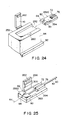
- FIG. 26 An example of the adapter comprising stationary jig 98 is illustrated in Fig. 26.
- Plate 402 has a groove 408 formed to receive optical fiber 40, and a liftable lid 404 is attached to the plate 402.
- Lid 404 has a rib 408 with a wave shape, as shown in Fig. 26, to restrict the lateral movement of optical fiber 40.
- Multicore optical fiber 40 is sandwiched between plate 402 and lid 404 of stationary jig 98 is fit in guid groove 282 of stationary jig 98 and is clamped by first clamp 10.
- Stationary jig 98 sandwiching optical fiber 40 is fit in guide groove 282 of the cutting apparatus of Fig. 21A and is then pressed by spring 292 by closing lid 254.
Landscapes
- Physics & Mathematics (AREA)
- General Physics & Mathematics (AREA)
- Optics & Photonics (AREA)
- Light Guides In General And Applications Therefor (AREA)
- Perforating, Stamping-Out Or Severing By Means Other Than Cutting (AREA)
- Mechanical Coupling Of Light Guides (AREA)
- Manufacture, Treatment Of Glass Fibers (AREA)
Priority Applications (1)
| Application Number | Priority Date | Filing Date | Title |
|---|---|---|---|
| EP19930110625 EP0568113B1 (de) | 1987-06-16 | 1988-03-29 | Gerät zum Schneiden einer optischen Glasfaser |
Applications Claiming Priority (8)
| Application Number | Priority Date | Filing Date | Title |
|---|---|---|---|
| JP92322/87 | 1987-06-16 | ||
| JP9232287U JPS63200802U (de) | 1987-06-16 | 1987-06-16 | |
| JP62268727A JPH0734046B2 (ja) | 1987-10-24 | 1987-10-24 | 光フアイバの切断方法 |
| JP1987163028U JPH0167602U (de) | 1987-10-24 | 1987-10-24 | |
| JP163028/87 | 1987-10-24 | ||
| JP268727/87 | 1987-10-24 | ||
| JP284844/87 | 1987-11-11 | ||
| JP62284844A JPH0778563B2 (ja) | 1987-11-11 | 1987-11-11 | 光フアイバの切断装置 |
Related Child Applications (4)
| Application Number | Title | Priority Date | Filing Date |
|---|---|---|---|
| EP19930110625 Division EP0568113B1 (de) | 1987-06-16 | 1988-03-29 | Gerät zum Schneiden einer optischen Glasfaser |
| EP93110624.9 Division-Into | 1988-03-29 | ||
| EP93110625.6 Division-Into | 1988-03-29 | ||
| EP19930110624 Division EP0568112B1 (de) | 1987-06-16 | 1988-03-29 | Gerät zum Schneiden einer optischen Glasfaser |
Publications (4)
| Publication Number | Publication Date |
|---|---|
| EP0295374A2 true EP0295374A2 (de) | 1988-12-21 |
| EP0295374A3 EP0295374A3 (en) | 1989-07-26 |
| EP0295374B1 EP0295374B1 (de) | 1994-03-09 |
| EP0295374B2 EP0295374B2 (de) | 1997-04-23 |
Family
ID=27468026
Family Applications (3)
| Application Number | Title | Priority Date | Filing Date |
|---|---|---|---|
| EP19880105121 Expired - Lifetime EP0295374B2 (de) | 1987-06-16 | 1988-03-29 | Vorrichtung und Verfahren zum Schneiden von optischen Fasern |
| EP19930110624 Expired - Lifetime EP0568112B1 (de) | 1987-06-16 | 1988-03-29 | Gerät zum Schneiden einer optischen Glasfaser |
| EP19930110625 Expired - Lifetime EP0568113B1 (de) | 1987-06-16 | 1988-03-29 | Gerät zum Schneiden einer optischen Glasfaser |
Family Applications After (2)
| Application Number | Title | Priority Date | Filing Date |
|---|---|---|---|
| EP19930110624 Expired - Lifetime EP0568112B1 (de) | 1987-06-16 | 1988-03-29 | Gerät zum Schneiden einer optischen Glasfaser |
| EP19930110625 Expired - Lifetime EP0568113B1 (de) | 1987-06-16 | 1988-03-29 | Gerät zum Schneiden einer optischen Glasfaser |
Country Status (3)
| Country | Link |
|---|---|
| US (3) | US5024363A (de) |
| EP (3) | EP0295374B2 (de) |
| DE (3) | DE3888242T3 (de) |
Cited By (7)
| Publication number | Priority date | Publication date | Assignee | Title |
|---|---|---|---|---|
| WO1991013837A1 (en) * | 1990-03-08 | 1991-09-19 | British Telecommunications Public Limited Company | Optical fibre handling |
| EP0387583A3 (de) * | 1989-03-11 | 1991-10-02 | Sumitomo Electric Industries, Ltd. | Schneidevorrichtung und -methode für optische Faser |
| EP0509737A3 (de) * | 1991-04-12 | 1992-12-30 | The Furukawa Electric Co., Ltd. | Vorrichtung zum Bearbeiten der Spitzen von ummantelten optischen Fasern |
| FR2694100A1 (fr) * | 1992-07-24 | 1994-01-28 | Mars Actel | Procédé de coupe droite d'un ruban de fibres optiques. |
| DE4322651C1 (de) * | 1993-07-07 | 1995-01-26 | Hirschmann Richard Gmbh Co | Verfahren und Vorrichtung für die Herstellung von schrägen Endflächen von Lichtwellenleitern in einem Faserband |
| EP0618466A3 (de) * | 1993-03-29 | 1995-10-11 | Minnesota Mining & Mfg | Verfahren und Gerät zum schrägen Durchtrennen von Fiberbändern. |
| US9933571B2 (en) | 2012-04-02 | 2018-04-03 | Oxford Fiber Ltd. | Profiling of cleaved angled end faces of optical fiber(s) |
Families Citing this family (50)
| Publication number | Priority date | Publication date | Assignee | Title |
|---|---|---|---|---|
| US5123581A (en) * | 1991-01-04 | 1992-06-23 | Bell Communications Research, Inc. | Oblique fracturing of optical fibers by offset shearing |
| FR2689805B1 (fr) * | 1992-04-14 | 1994-06-03 | Boitel Michel | Appareil de coupe oblique d'une ou de plusieurs fibres optiques. |
| US5414919A (en) * | 1992-06-08 | 1995-05-16 | Hughes Aircraft Company | Apparatus for removing metallized leads bonded to metallized bond pads |
| DE29504071U1 (de) * | 1994-03-15 | 1995-07-20 | Minnesota Mining And Mfg. Co., Saint Paul, Minn. | Vorrichtung zum Trennen optischer Fasern |
| FR2729767B1 (fr) * | 1995-01-23 | 1997-04-11 | Pouyet Henri | Dispositif de fixation d'au moins un ruban de fibres optiques |
| CA2284882A1 (en) * | 1997-04-14 | 1998-10-22 | Larry R. Cox | Optical fiber holder and end-face preparation tool |
| US5813902A (en) * | 1997-04-14 | 1998-09-29 | Minnesota Mining And Manufacturing Company | Optical fiber end-face preparation and connector assembly |
| AU760606B2 (en) * | 1997-04-14 | 2003-05-15 | Minnesota Mining And Manufacturing Company | Optical fibre holder and end-face preparation tool |
| GB9711133D0 (en) * | 1997-05-30 | 1997-07-23 | Murgatroyd I J | Device for cleaving angled ends onto optical fibers |
| WO1999027392A2 (en) * | 1997-11-24 | 1999-06-03 | Corning Incorporated | Fiber array cleaving |
| SE513049C2 (sv) | 1997-12-19 | 2000-06-26 | Ericsson Telefon Ab L M | Anordning för att fixera fibrer |
| US6085004A (en) * | 1998-02-03 | 2000-07-04 | 3M Innovative Properties Company | Optical fiber connector using photocurable adhesive |
| US6196730B1 (en) | 1998-06-22 | 2001-03-06 | 3M Innovative Properties Company | Fiber optic connector containing a curable adhesive composition |
| US6331080B1 (en) | 1998-07-15 | 2001-12-18 | 3M Innovative Properties Company | Optical fiber connector using colored photocurable adhesive |
| JP3956500B2 (ja) * | 1998-09-11 | 2007-08-08 | 古河電気工業株式会社 | 光ファイバ切断器 |
| JP3813369B2 (ja) * | 1999-01-05 | 2006-08-23 | 古河電気工業株式会社 | 光ファイバ切断器 |
| DE19903569A1 (de) * | 1999-01-29 | 2000-08-24 | Siemens Ag | Vorrichtung zum Trennen von mindestens einer lichtleitenden Faser |
| US6456685B1 (en) | 2000-06-29 | 2002-09-24 | Axe, Inc. | Method and apparatus for cutting waveguides to precise differential lengths using time-domain-reflectometry |
| AU6948701A (en) * | 2000-07-10 | 2002-01-21 | Sumitomo Electric Industries, Ltd. | Optical fiber wire holder, fused connection device, cutting device, and method of connecting optical fiber |
| US20020130152A1 (en) * | 2001-03-19 | 2002-09-19 | Amherst Holding Co. | Optical fiber cleaver with traversing mechanism |
| JP4065749B2 (ja) * | 2001-10-23 | 2008-03-26 | 株式会社フジクラ | 光ファイバ切断機およびこれを用いた光ファイバ切断方法 |
| TW545365U (en) * | 2001-12-13 | 2003-08-01 | Ind Tech Res Inst | Handheld optical fiber cutting apparatus |
| WO2004076107A1 (ja) * | 2002-08-26 | 2004-09-10 | Ilsin Precision Co.,Ltd. | 光ファイバ自動切断器 |
| WO2004036277A1 (de) * | 2002-10-14 | 2004-04-29 | Diamond Sa | Verfahren und vorrichtung zum spleissen von lichtwellenleitern durch eine schmelzverbindung |
| US7669744B2 (en) * | 2003-08-04 | 2010-03-02 | 3M Innovative Properties Company | Device and method for cleaving optical fibers |
| DE10360105A1 (de) * | 2003-12-20 | 2005-07-21 | Krone Gmbh | Anschlussmodul für die Telekommunikations- und Datentechnik |
| GB0502242D0 (en) * | 2005-02-04 | 2005-03-09 | Oxford Fiber Ltd | Cleaving apparatus |
| US7588438B2 (en) * | 2005-11-01 | 2009-09-15 | The Board Of Regents, The University Of Texas System | System, method and apparatus for fiber sample preparation for image analysis |
| DE102006012582B4 (de) * | 2006-03-16 | 2010-01-21 | Schott Ag | Vorrichtung und Verfahren zum Abtrennen von Abschnitten von Glasstangen |
| JP5326198B2 (ja) * | 2006-10-04 | 2013-10-30 | 住友電気工業株式会社 | 光ファイバの切断装置及び光ファイバの切断方法 |
| DE102007019797A1 (de) * | 2007-04-26 | 2008-10-30 | CCS Technology, Inc., Wilmington | Vorrichtung zum Spleißen von Lichtwellenleitern |
| WO2008134507A1 (en) * | 2007-04-27 | 2008-11-06 | Furukawa Electric North America, Inc. | Optical fiber cleave tool |
| JP5425087B2 (ja) * | 2007-10-19 | 2014-02-26 | スリーエム イノベイティブ プロパティズ カンパニー | ブレードレス光ファイバクリーバ及びその方法 |
| CN102326109B (zh) * | 2009-01-19 | 2014-04-09 | 康宁光缆系统有限责任公司 | 用于光纤连接的端接系统 |
| KR101267182B1 (ko) * | 2010-01-22 | 2013-05-24 | 센주긴조쿠고교 가부시키가이샤 | 땜납 칼럼의 제조 방법, 땜납 칼럼의 제조 장치 및 땜납 칼럼 |
| AU2010200788B2 (en) | 2010-03-02 | 2015-02-12 | Tyco Electronics Services Gmbh | Method and apparatus for mechanically cleaving a stripped end section of an optic fibre core |
| US9042698B2 (en) * | 2010-03-23 | 2015-05-26 | Afl Telecommunications Llc | Bare glass fiber holder |
| US9841562B2 (en) * | 2010-04-07 | 2017-12-12 | Corning Optical Communications LLC | Fiber devices with displaceable fiber guide |
| US8792764B1 (en) | 2010-12-22 | 2014-07-29 | Lee Technologies, Inc. | Optical fiber cleaver |
| US8979395B2 (en) * | 2011-09-07 | 2015-03-17 | Adc Telecommunications, Inc. | Tools and methods for preparing a ferrule-less optical fiber connector |
| US8985867B2 (en) | 2011-09-07 | 2015-03-24 | Adc Telecommunications, Inc. | Optical fiber connection system |
| CN202600181U (zh) * | 2012-03-31 | 2012-12-12 | 一诺仪器(威海)有限公司 | 新型多功能熔接夹具 |
| CN104641270A (zh) * | 2012-07-12 | 2015-05-20 | 泰科电子瑞侃有限公司 | 光纤切断机构和其使用方法 |
| KR101915590B1 (ko) * | 2012-10-18 | 2018-11-06 | 이노 인스트루먼트 (차이나). 인코퍼레이션 | 전자동 광섬유 절단기 |
| US9541710B2 (en) * | 2015-01-30 | 2017-01-10 | Fujikura Ltd. | Optical fiber holding device |
| BR112018014991A2 (pt) | 2016-01-22 | 2018-12-18 | Fujikura Ltd | suporte e método de processamento de uma fibra ótica |
| JP6593794B2 (ja) * | 2016-02-12 | 2019-10-23 | Seiオプティフロンティア株式会社 | 光ファイバホルダおよび当該光ファイバホルダが取付可能な光ファイバ切断装置 |
| US9864146B1 (en) * | 2016-11-18 | 2018-01-09 | Inphi Corporation | Fiber tray apparatus and method for handling a fiber-array/silicon-photonics-die assembly |
| US10656335B2 (en) * | 2018-07-18 | 2020-05-19 | International Business Machines Corporation | Cleaving fibers of differing composition |
| US10739517B2 (en) * | 2018-09-21 | 2020-08-11 | Ofs Fitel, Llc | Cleaving optical fibers |
Family Cites Families (17)
| Publication number | Priority date | Publication date | Assignee | Title |
|---|---|---|---|---|
| US3934773A (en) * | 1973-11-02 | 1976-01-27 | Bell Telephone Laboratories, Incorporated | Method for breaking brittle rods or fibers |
| US4073020A (en) * | 1976-04-19 | 1978-02-14 | The Goodyear Tire & Rubber Company | Contoured foam mattress |
| GB1537772A (en) * | 1976-08-13 | 1979-01-04 | Post Office | Dielectric optical waveguide severing apparatus |
| JPS5426751A (en) * | 1977-08-01 | 1979-02-28 | Nippon Telegr & Teleph Corp <Ntt> | Cutting method and apparatus for optical fiber |
| GB2034069A (en) * | 1978-10-10 | 1980-05-29 | Post Office | Joining optical fibres |
| GB2046242A (en) * | 1979-03-08 | 1980-11-12 | Secr Defence | Fibre optic cleaving tool |
| DE3017873A1 (de) * | 1980-05-09 | 1981-11-12 | Siemens AG, 1000 Berlin und 8000 München | Verfahren und vorrichtung zum trennen von mehreren in einem kabel vereinigten lichtwellenleitern |
| FR2487812B1 (fr) * | 1980-07-31 | 1985-06-07 | Socapex | Outillage de cassure collective de fibres optiques |
| DE3174281D1 (en) * | 1981-12-30 | 1986-05-07 | Amp Inc | Tool for cutting optical fibres |
| US4463886A (en) * | 1982-04-12 | 1984-08-07 | Augat Inc. | Cleaving tool for optical fibers |
| US4621754A (en) * | 1983-01-03 | 1986-11-11 | Switchcraft, Inc. | Tool and method for cleaving optical fibers |
| GB2134101B (en) * | 1983-01-05 | 1986-08-13 | Gen Electric Co Plc | Method of and apparatus for cleaving optical fibres |
| DE3322127A1 (de) * | 1983-06-20 | 1984-12-20 | Siemens AG, 1000 Berlin und 8000 München | Verfahren und vorrichtung zum trennen von lichtwellenleitern |
| JPS60184207A (ja) * | 1984-03-03 | 1985-09-19 | Fujikura Ltd | 光ファイバの切断方法 |
| JPS623208A (ja) * | 1985-06-28 | 1987-01-09 | Sumitomo Electric Ind Ltd | 光フアイバの接続方法 |
| US4619387A (en) * | 1985-09-16 | 1986-10-28 | Gte Products Corporation | Fiber optic cleaving tool |
| JP2850910B2 (ja) * | 1988-06-22 | 1999-01-27 | 住友電気工業株式会社 | 光ファイバの切断装置 |
-
1988
- 1988-03-28 US US07/174,072 patent/US5024363A/en not_active Expired - Lifetime
- 1988-03-29 DE DE3888242T patent/DE3888242T3/de not_active Expired - Lifetime
- 1988-03-29 DE DE3856256T patent/DE3856256T2/de not_active Expired - Lifetime
- 1988-03-29 EP EP19880105121 patent/EP0295374B2/de not_active Expired - Lifetime
- 1988-03-29 EP EP19930110624 patent/EP0568112B1/de not_active Expired - Lifetime
- 1988-03-29 DE DE3856344T patent/DE3856344T2/de not_active Expired - Lifetime
- 1988-03-29 EP EP19930110625 patent/EP0568113B1/de not_active Expired - Lifetime
-
1990
- 1990-10-31 US US07/606,103 patent/US5129567A/en not_active Expired - Lifetime
-
1991
- 1991-01-03 US US07/637,066 patent/US5106006A/en not_active Expired - Lifetime
Cited By (10)
| Publication number | Priority date | Publication date | Assignee | Title |
|---|---|---|---|---|
| EP0387583A3 (de) * | 1989-03-11 | 1991-10-02 | Sumitomo Electric Industries, Ltd. | Schneidevorrichtung und -methode für optische Faser |
| US5104021A (en) * | 1989-03-11 | 1992-04-14 | Sumitomo Electric Industries, Ltd. | Optical fiber cutting apparatus and method |
| WO1991013837A1 (en) * | 1990-03-08 | 1991-09-19 | British Telecommunications Public Limited Company | Optical fibre handling |
| EP0509737A3 (de) * | 1991-04-12 | 1992-12-30 | The Furukawa Electric Co., Ltd. | Vorrichtung zum Bearbeiten der Spitzen von ummantelten optischen Fasern |
| US5253412A (en) * | 1991-04-12 | 1993-10-19 | The Furukawa Electric Co., Ltd. | Tip processing apparatus for jacketed optical fibers |
| US5469611A (en) * | 1991-04-12 | 1995-11-28 | The Furukawa Electric Co., Ltd. | Tip processing method for jacketed optical fibers |
| FR2694100A1 (fr) * | 1992-07-24 | 1994-01-28 | Mars Actel | Procédé de coupe droite d'un ruban de fibres optiques. |
| EP0618466A3 (de) * | 1993-03-29 | 1995-10-11 | Minnesota Mining & Mfg | Verfahren und Gerät zum schrägen Durchtrennen von Fiberbändern. |
| DE4322651C1 (de) * | 1993-07-07 | 1995-01-26 | Hirschmann Richard Gmbh Co | Verfahren und Vorrichtung für die Herstellung von schrägen Endflächen von Lichtwellenleitern in einem Faserband |
| US9933571B2 (en) | 2012-04-02 | 2018-04-03 | Oxford Fiber Ltd. | Profiling of cleaved angled end faces of optical fiber(s) |
Also Published As
| Publication number | Publication date |
|---|---|
| DE3888242T2 (de) | 1994-09-22 |
| EP0568113A3 (en) | 1995-09-27 |
| EP0568112A3 (en) | 1995-09-27 |
| EP0568112B1 (de) | 1998-10-07 |
| DE3888242D1 (de) | 1994-04-14 |
| EP0295374B1 (de) | 1994-03-09 |
| US5129567A (en) | 1992-07-14 |
| EP0295374A3 (en) | 1989-07-26 |
| DE3856344D1 (de) | 1999-07-29 |
| EP0568113B1 (de) | 1999-06-23 |
| DE3888242T3 (de) | 1997-10-09 |
| DE3856344T2 (de) | 2000-02-24 |
| EP0568112A2 (de) | 1993-11-03 |
| DE3856256T2 (de) | 1999-06-02 |
| EP0568113A2 (de) | 1993-11-03 |
| EP0295374B2 (de) | 1997-04-23 |
| DE3856256D1 (de) | 1998-11-12 |
| US5106006A (en) | 1992-04-21 |
| US5024363A (en) | 1991-06-18 |
Similar Documents
| Publication | Publication Date | Title |
|---|---|---|
| EP0295374A2 (de) | Vorrichtung und Verfahren zum Schneiden von optischen Fasern | |
| JP3264792B2 (ja) | 細長い素子を位置付けする装置および方法 | |
| EP1302790B1 (de) | Schmelzspleissvorrichtung und Schneidevorrichtung für optische Fasern | |
| US6634079B1 (en) | Optical fiber cleaver | |
| JPWO2002004998A1 (ja) | 光ファイバ素線ホルダ、融着接続装置、切断装置及び光ファイバの接続方法 | |
| KR101163793B1 (ko) | 섬유 접속 장치 | |
| KR0140080Y1 (ko) | 스플라이스 작동 공구 | |
| JPS6212883B2 (de) | ||
| JPS62251705A (ja) | 2個の光フアイバ群の端部を対をなすように連結する装置 | |
| JPH02153305A (ja) | 光ファイバテープ心線の分岐方法および分岐用工具 | |
| JP2005134583A (ja) | 光ファイバ接続工具 | |
| JPH0529443Y2 (de) | ||
| JP3535028B2 (ja) | 光ファイバ突合わせ接続用工具 | |
| JP3791028B2 (ja) | 光ファイバ接続部材および接続方法 | |
| JPH11264909A (ja) | 光ファイバカッタ | |
| JPH07104452B2 (ja) | 多心被覆光フアイバ融着接続用クランプ方法 | |
| JP2670268B2 (ja) | 光フアイバ素線の端面切断装置及び光フアイバ素線の端面切断方法 | |
| JPH0734046B2 (ja) | 光フアイバの切断方法 | |
| JP3345848B2 (ja) | 光ファイバ融着接続方法とその装置 | |
| JP3190942B2 (ja) | 光ファイバ接続用作業台 | |
| JPH05281433A (ja) | 光ファイバ接続器用作業台 | |
| JP3691122B2 (ja) | 簡易形光スイッチ | |
| JPH0740749U (ja) | 光ファイバー切断工具 | |
| JPH09127356A (ja) | 光ファイバ接続工具 | |
| JPH07301720A (ja) | 多心光ファイバのクランプ装置 |
Legal Events
| Date | Code | Title | Description |
|---|---|---|---|
| PUAI | Public reference made under article 153(3) epc to a published international application that has entered the european phase |
Free format text: ORIGINAL CODE: 0009012 |
|
| 17P | Request for examination filed |
Effective date: 19880329 |
|
| AK | Designated contracting states |
Kind code of ref document: A2 Designated state(s): DE GB |
|
| PUAL | Search report despatched |
Free format text: ORIGINAL CODE: 0009013 |
|
| AK | Designated contracting states |
Kind code of ref document: A3 Designated state(s): DE GB |
|
| RHK1 | Main classification (correction) |
Ipc: C03B 37/16 |
|
| 17Q | First examination report despatched |
Effective date: 19920317 |
|
| GRAA | (expected) grant |
Free format text: ORIGINAL CODE: 0009210 |
|
| AK | Designated contracting states |
Kind code of ref document: B1 Designated state(s): DE GB |
|
| XX | Miscellaneous (additional remarks) |
Free format text: TEILANMELDUNG 93110625.6 EINGEREICHT AM 29/03/88. |
|
| REF | Corresponds to: |
Ref document number: 3888242 Country of ref document: DE Date of ref document: 19940414 |
|
| PLBI | Opposition filed |
Free format text: ORIGINAL CODE: 0009260 |
|
| 26 | Opposition filed |
Opponent name: SIEMENS AKTIENGESELLSCHAFT ABT. ZFE GR PA 7 Effective date: 19941209 |
|
| PLAW | Interlocutory decision in opposition |
Free format text: ORIGINAL CODE: EPIDOS IDOP |
|
| PLAW | Interlocutory decision in opposition |
Free format text: ORIGINAL CODE: EPIDOS IDOP |
|
| PUAH | Patent maintained in amended form |
Free format text: ORIGINAL CODE: 0009272 |
|
| STAA | Information on the status of an ep patent application or granted ep patent |
Free format text: STATUS: PATENT MAINTAINED AS AMENDED |
|
| 27A | Patent maintained in amended form |
Effective date: 19970423 |
|
| AK | Designated contracting states |
Kind code of ref document: B2 Designated state(s): DE GB |
|
| REG | Reference to a national code |
Ref country code: GB Ref legal event code: IF02 |
|
| PGFP | Annual fee paid to national office [announced via postgrant information from national office to epo] |
Ref country code: GB Payment date: 20070328 Year of fee payment: 20 |
|
| PGFP | Annual fee paid to national office [announced via postgrant information from national office to epo] |
Ref country code: DE Payment date: 20070524 Year of fee payment: 20 |
|
| REG | Reference to a national code |
Ref country code: GB Ref legal event code: PE20 Expiry date: 20080328 |
|
| PG25 | Lapsed in a contracting state [announced via postgrant information from national office to epo] |
Ref country code: GB Free format text: LAPSE BECAUSE OF EXPIRATION OF PROTECTION Effective date: 20080328 |