EP0295678B1 - Funktelefon-System - Google Patents
Funktelefon-System Download PDFInfo
- Publication number
- EP0295678B1 EP0295678B1 EP88109648A EP88109648A EP0295678B1 EP 0295678 B1 EP0295678 B1 EP 0295678B1 EP 88109648 A EP88109648 A EP 88109648A EP 88109648 A EP88109648 A EP 88109648A EP 0295678 B1 EP0295678 B1 EP 0295678B1
- Authority
- EP
- European Patent Office
- Prior art keywords
- radio
- radio telephone
- telephone set
- connector
- zone
- Prior art date
- Legal status (The legal status is an assumption and is not a legal conclusion. Google has not performed a legal analysis and makes no representation as to the accuracy of the status listed.)
- Expired - Lifetime
Links
Images


Classifications
-
- H—ELECTRICITY
- H04—ELECTRIC COMMUNICATION TECHNIQUE
- H04W—WIRELESS COMMUNICATION NETWORKS
- H04W60/00—Affiliation to network, e.g. registration; Terminating affiliation with the network, e.g. de-registration
- H04W60/04—Affiliation to network, e.g. registration; Terminating affiliation with the network, e.g. de-registration using triggered events
-
- H—ELECTRICITY
- H04—ELECTRIC COMMUNICATION TECHNIQUE
- H04W—WIRELESS COMMUNICATION NETWORKS
- H04W52/00—Power management, e.g. Transmission Power Control [TPC] or power classes
- H04W52/02—Power saving arrangements
- H04W52/0209—Power saving arrangements in terminal devices
- H04W52/0212—Power saving arrangements in terminal devices managed by the network, e.g. network or access point is leader and terminal is follower
- H04W52/0216—Power saving arrangements in terminal devices managed by the network, e.g. network or access point is leader and terminal is follower using a pre-established activity schedule, e.g. traffic indication frame
-
- Y—GENERAL TAGGING OF NEW TECHNOLOGICAL DEVELOPMENTS; GENERAL TAGGING OF CROSS-SECTIONAL TECHNOLOGIES SPANNING OVER SEVERAL SECTIONS OF THE IPC; TECHNICAL SUBJECTS COVERED BY FORMER USPC CROSS-REFERENCE ART COLLECTIONS [XRACs] AND DIGESTS
- Y02—TECHNOLOGIES OR APPLICATIONS FOR MITIGATION OR ADAPTATION AGAINST CLIMATE CHANGE
- Y02D—CLIMATE CHANGE MITIGATION TECHNOLOGIES IN INFORMATION AND COMMUNICATION TECHNOLOGIES [ICT], I.E. INFORMATION AND COMMUNICATION TECHNOLOGIES AIMING AT THE REDUCTION OF THEIR OWN ENERGY USE
- Y02D30/00—Reducing energy consumption in communication networks
- Y02D30/70—Reducing energy consumption in communication networks in wireless communication networks
Definitions
- the present invention relates to a radio telephone system used for cordless telephone, automobile telephone or the like, according to the pre-characterizing clause of claim 1 (37th IEEE VEHICULAR TECHNOLOGY CONFERENCE, Tampa, Florida, 1-3 June 1987, pages 579-586, IEEE, New York, US; T. HATTORI et al.).
- Said radio telephone system comprising a plurality of radio telephone sets (RTEL) such as cordless telephone sets or automobile telephone sets making up mobile stations, a plurality of radio connectors (CE) arranged in a plurality of radio zones respectively for radio communication with the radio telephone sets, a radio channel control unit (RCU) for communicating with the radio connectors (CE) and a private branche exchange (PBX), an office exchange or the like exchange connector connected with the radio channel control unit (RCU), thereby to establish communications between different radio telephone sets (RTEL) or through a trunk line of the radio telephone sets (RTEL).
- RTEL radio telephone sets
- RTEL radio telephone sets
- CE radio connectors
- RCU radio channel control unit
- PBX private branche exchange
- RCU private branche exchange
- the radio channel control unit (RCU) and the radio connector (CE) mentioned above are similar to the system control station and a base station of each radio zone in the automobile telephone system, respectively.
- the position data indicating each radio zone is constantly announced by the radio connector (CE) providing a stationary station in order to register the radio zone covering a radio telephone set (RTEL), so that each radio telephone set (RTEL) constantly monitors the present radio zone by this position data.
- the radio telephone set When moving between radio zones, the radio telephone set thus sends out a position entry demand signal and an ID number automatically thereby to register the position data of each radio telephone set (RTEL) with the radio channel control unit (RCU).
- the conventional radio telephone system described above is required to keep on the power supply of the radio telephone sets (RTEL) making up mobile stations in order to keep monitoring the position data from the radio connectors, thereby posing the problem of power consumption by the radio telephone sets (RTEL).
- RTEL radio telephone sets
- the object of the present invention is to provide a radio telephone system capable of registering the position of a radio telephone set automatically while saving power consumption thereof.
- a transmission method in staff location systems comprising means for reducing power consumption of receiving circuits.
- Said means includes logic circuits capable of registration of the remaining duration of the search signal in order to disconnect electric current for said duration of the remaining search signal time and to reconnect it at the change-over to an information signal following the search signal.
- the position of each radio telephone set is capable of being registered without keeping on the power supply of the receiving circuit of the radio telephone set, thereby saving the power consumption of the radio telephone set.
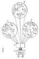
- reference numeral 11 designates a stationary station connected to an existing telephone exchange 10, which makes up a radio channel control unit (RCU) for controlling the radio telephone system as a whole.
- Numeral 121 to 12 n designate stationary stations providing small-power radio connectors (CE) with a communication radius of about 30 to 100 m, each of the radio connectors 121 to 12 n including a plurality of units.
- Each of the radio connectors 121 to 12 n makes up each corresponding one of radio zones Z1 to Z n to establish radio communication with a radio telephone set (RTEL) located in a corresponding radio zone.
- RTEL radio telephone set
- Each of the radio zones Z1 to Z n makes up a radio service area under the control of the radio channel control unit 11.
- An operator carrying a radio telephone set 13 (in the case of cordless telephone), when located within this service area, is capable of establishing communication with other radio telephone sets 13 or through the trunk line by way of the radio channel control unit 11 and the radio connectors 121 to 12 n .
- the radio channel control unit 11 is connected to the existing telephone exchange 10 through as many telephone lines as the radio telephone sets 13.
- the radio connectors 121, 122 to 12 n are arranged in the radio zones Z1, Z2 to Z n respectively at the rate of one for each several radio telephone sets 13 in accordance with the busy-hour traffic and loss probability.
- control section 110 designates a control section for controlling the radio channel control unit 11 as a whole.
- the control section 110 includes a microcomputer (CPU), a ROM (read-only memory) for storing an execution program for the CPU, and a RAM (random access memory) having a working area for the CPU, etc.
- Numerals 1111 to 111 N designate trunk interfaces connected with telephone lines respectively, numeral 112 a tone trunk for generating various tone signals, numeral 1131 to 113 m radio channel interfaces connected to the radio connectors 121 to 12 n respectively, and numeral 114 a matrix switch for connecting the trunk interfaces 1111 to 111 N , the tone trunk 112 and the radio channel interfaces 1131 to 113 m .
- Numeral 115a designates, as shown in Fig. 3A, a system file for storing various data including the ID number of the radio channel control unit, that is, the ID number (SYS-ID) of the present system, the number n of radio zones, that is, the number of control stations for the radio connectors 12, the number of the radio connectors 12, station data for the radio connectors such as the monitor timer value, and further including, though not shown, such data as the program for the control section 120 of the radio connector 12 and various data to be stored in the radio channel connection file 125a and the station data file 125b.
- the ID number of the radio channel control unit that is, the ID number (SYS-ID) of the present system
- the number n of radio zones that is, the number of control stations for the radio connectors 12, the number of the radio connectors 12, station data for the radio connectors such as the monitor timer value
- station data for the radio connectors
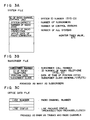
- Numeral 115b designates, as shown in Fig. 3B, a subscriber file for storing call numbers (subscriber numbers) of the radio telephone sets 13, ID number (RTEL-ID), the position data such as the radio zone number of the current position and data on subscriber class. The position data is rewritten upon movement of the radio telephone 13 between radio zones as described below.
- Numeral 115c designates, as shown in Fig. 3C, a station data file for storing the numbers of the trunk lines and radio channels, and other various data including the channel status indicating the present packaging condition of a given channel.
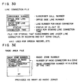
- Numeral 115e designates, as shown in Fig. 3D, a line connection file for storing the call number (subscriber number) for the subscriber in speech, the line number of the trunk line, the line number with the radio connectors, the status of incoming/outgoing calls and line connection time.
- Numeral 115f designates, as shown in Fig. 3E, a radio area file for storing various data including the numbers of the radio zones, the number of the radio connectors installed in the radio zones, and the ID numbers of the radio connectors.
- Numeral 116 designates a control console by which the operator enters various data in the files 115a to 115f or the monitor result on the radio connectors 12 making up control stations are displayed.
- control section 120 designates a control section for controlling each radio connector 12 in whole.
- the control section 120 generally includes a microcomputer (CPU), a ROM (read-only memory) for storing an execution program for the CPU, and a RAM (random access memory) having a work area of the CPU, etc.
- Numeral 121 designates a radio transceiver of multi-channel access (MCA) type for performing radio communication with the radio telephone 13, numeral 122 a line interface connected to the radio channel control unit 11 through a two-wire (2W) transmission path, numeral 123 a control signal transceiver for transmitting and receiving the control signal with the radio channel control unit 11, and numeral 124 a voice control section for turning on/off or amplifying the voice signal on the speech line.
- MCA multi-channel access
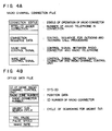
- Numeral 125a designates, as shown in Fig. 4A, a radio channel connection file for storing various data including the present operating condition of a particular radio connector 12, the ID number (RTEL-ID) of the radio telephone in connection, the control sequence for processing incoming/outgoing calls, various control signals for the radio telephone 13 (radio side) and various control signals for the radio channel control unit (wire side).
- Numeral 125b designates, as shown in Fig. 4B, an office data file for storing various data including the ID numbers (SYS-ID) of the radio channel control unit 11, the number of the radio zone in which a particular radio connector is installed, the ID number of the particular radio connector, the dial pause time for line wire transmission or the like, the speed of the dial pulse (10 pps or 20 pps), the make ratio of the dial pulse (33%, 50% or 66%).
- ID numbers SYS-ID
- control section 130 designates a control section for controlling each radio telephone set 13 in whole.
- the control section 130 generally includes a micro-computer (CPU), a ROM (read-only memory) for storing an execution program for the CPU, and a RAM (random access memory) with a work area for the CPU or the like.
- CPU micro-computer
- ROM read-only memory
- RAM random access memory
- Numeral 131 designates a radio transceiver of multi-channel access (MCA) type for effecting radio communication with the radio connector 12, numeral 132 a transceiver for amplifying or turning on/off the voice signal of the receiver or microphone of the handset 132a and generating various tone signals (voice signals) corresponding to the call signals or the like sent out from the radio channel control unit 11 through the radio connector 12, numeral 133 a dial key for entering a dial number or the like, numeral 134 a hook switch turned on/off by the off-hook/on-hook state of the handset 132a, and numeral 136 a PB/DP change-over switch for selecting the type (PB or DP) of the dial signal for the existing exchange 10.
- MCA multi-channel access
- Numeral 138a designates, as shown in Fig. 5A, a radio channel connection file for storing various data including the connections of a particular telephone set, the number of the radio connector 12 in connection, the system number (SYS-ID) of the radio channel control unit 11 in connection, the connection sequence with the radio connector 12 and the control signal for the radio connector 12.
- SYS-ID system number
- Numeral 138b designates, as shown in Fig. 5B, a radio telephone set ID file for storing the ID number (RTEL-ID) of a particular telephone set 13, numeral 138c a radio zone number file as shown in Fig. 5C for storing the number (position data) of the radio zone in which a particular radio telephone set 13 is located, numeral 138d an abbreciated dial file as shown in Fig. 5D for storing an abbreviated dial number with a corresponding dial code, and numeral 138e a redial file as shown in Fig. 5E for storing a dial code corresponding to the dial number entered through the dial key the previous time.
- RTEL-ID ID number
- Fig. 5C for storing the number (position data) of the radio zone in which a particular radio telephone set 13 is located
- numeral 138d an abbreciated dial file as shown in Fig. 5D for storing an abbreviated dial number with a corresponding dial code
- numeral 138e
- the members 130 to 138e described above are encased in a portable housing for the cordless telephone set, and a housing that can be installed on the center console or the like of an automobile for the automobile telephone set.
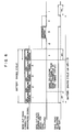
- the control section 130 of the radio telephone set 13, except while busy, turns on/off the power supply in a battery-saving ratio of, say, 1 to 3, and while this power supply is off, is supplied with a minimum power (for counting the battery saving period, for example).
- the radio channel control unit 11 inverts the polarity of the transmission line loop to invert the applied voltage for each radio connector 12 (control station) of each radio zone in a predetermined cycle (say, 5 minutes) (sequence (hereinafter referred to SQ) 1), sends out a sync signal (SQ2) and restores the polarity of the loop (SQ4).
- the radio connector 12 making up the control station of each radio zone generates a position data announcing signal with the system ID number (SYS-ID) and the radio zone number in the office data file 125b following a preamble signal and a sync signal in response to the control sequence in the radio channel connection file 125a, the control signal and the sync signal, and sends out as a poling signal through the radio transceiver 121 (SQ3).
- SYS-ID system ID number
- SQ3 radio transceiver 121
- This announcement is repeatedly effected during a time period (+ time ⁇ ) longer than the battery saving cycle of the radio telephone set 13. Specifically, the operation of SQ1 to SQ4 are repeated in five time slots in the case where the the battery-saving cycles of the radio telephone 13 occurs in the ratio of 1 to 3 as shown in Fig. 6.
- each radio telephone set 13 is capable of receiving a position data announcing signal from the radio connector 12 while the power supply of its own is on.
- Fig. 6 shows the case where the position data announcing signal has begun to be received at time slot 1.
- reset timing it is possible to reset at a time when the radio zone number of the received position data announcing signal and the radio zone number stored in the radio zone number file 138c coincide with each other in the comparison of the two radio zone numbers.
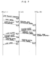
- the power of the receiving circuit is turned on/off in the battery saving cycles. If these data fail to coincide with each other a predetermined number of times successively in the successive plural comparisons at times of receiving the position data announcing signal, on the other hand, the control section 130 generates a position entry demand signal including a preamble signal and a sync signal with the ID number of the radio telephone set and the received radio zone number in response to the control signal and the control sequence in the radio channel connection file 138a and transmits it through the radio transceiver 131 (SQ5).
- This position entry demand signal is transmitted at random after receiving the position data announcing signal from the radio connector 12.
- the timing of transmitting the position entry demand signal is determined by random numbers, for example, or the ID number of an associated radio telephone set is divided by the number of time slots, and the remainder is used to determine the time slot in which transmission is effected.
- Fig. 6 shows the case of transmission in the third time slot.
- the radio connector 12 upon receiving the position entry demand signal, transmits a position entry response signal to the radio telephone set 13 (SQ6), which rewrites the area of the radio zone number file 138c into the ID number of the radio zone received.
- the radio connector 12 also closes the loop of the transmission path with the radio channel control unit 11 (SQ7), and generates and transmits a position entry demand signal to the radio channel control unit 11 (SQ8).
- the radio channel control unit 11 rewrites the position data of the subscriber file 115b in response to the position entry demand signal and transmits a position entry over signal to the radio connector 12 (SQ9).
- the radio connector 12 transmits the position entry over signal to the radio telephone set 13 (SQ10), while at the same time opening the loop with the radio channel control unit 11 (SQ11).
- the radio telephone set 13 upon receiving the position entry over signal, turns on or off the power supply of the receiving circuit in the battery saving cycles.
- the position entry demand signal which is supplied as a special signal from the radio connector 12 to the radio channel control unit 11 may be replaced by some means of notification by opening or closing a line loop. Also, instead of the position entry over signal from the radio channel control unit 11 to the radio connector 12 may be replaced by some means of polarity inversion of the line voltage or by sending a tone signal directly to the radio telephone set 13 or sending the tone signal as a code signal.
- the control section 130 of the radio telephone set 13 turns on and off the power supply of the receiving circuit thereof in battery saving cycles in the ratio of, say, 1 to 3 except when busy, and while the power supply is off, supplies only minimum power (such as for counting the battery saving time).
- the position data of the radio telephone set 13 can be entered in the subscriber file 115b of the radio channel control unit 11.
- the existing exchange 10 accesses the control section 110 of the radio channel control unit 11 through the trunk interface 111 receiving the call.
- the control section 110 reads out the radio zone associated with the radio telephone (13X1) from the subscriber file 115b, and sends out the ID number of the radio telephone set (13X1) and a call control signal to the control station of the radio connector 12 arranged in the particular radio zone. In the process, the control section 110 controls a matrix switch 114 thereby to connect the radio channel interface corresponding to the control station of the radio connector 12 for the particular radio zone with the trunk interface 111 associated with the incoming call.
- the control section 120 of the radio connector 12 upon receiving the call signal and the like through the line interface 122 and the control signal transceiver 123, generates the call control signal and the ID number for the radio telephone set (13X1) for radio communication on the basis of the control signal data of the radio channel connection file 125a, transmits these signals repeatedly for a time period (+ ⁇ ) longer than the battery saving cycle of the radio telephone set 13 like the pattern shown as a calling signal in Fig. 6.
- the control section 130 of the radio telephone set 13, as explained with reference to Fig. 6, turns on/off the power supply of the receiving circuit in predetermined battery-saving cycles, and when the power supply is on, receives a call control signal and a signal representing the ID number of the radio telephone set (13X1) thereby to keep the power on. Then, the ID number received is compared with the ID number in the radio telephone set ID file 138b, so that the control section 130 of the radio telephone set (13X1) for which the ID numbers coincide with each other turns on the transceiving section 132 thereof. The transceiving section 132 thus generates a voice signal for calling in response to a control signal from the radio connector 12.
- calling signals from the existing exchange 10 are transmitted in sequentially different signal formats to the radio telephone set (13X1) through the radio channel control unit 11 and the control section of the radio connector 12.
- the particular data is sent out to the control station of the radio connector 12 and the radio channel control unit 11, so that the control section 120 of the radio connector 11 establishes a communication path with the calling telephone set and the radio telephone set (13X1) by turning on the voice control section 124.
- control section 130 of the radio telephone set 13 Upon termination of speech, the control section 130 of the radio telephone set 13 turns on the power supply and restarts the battery saving cycles.
- the power supply With the off-hook of the radio telephone set 13 to turn on the hook switch 134, the power supply is turned on, and the associated control section 130 generates a calling signal in response to the connection sequence and the control signal in the radio channel connection file 135 and together with the ID number of the present radio zone in the radio zone number file 138c, sends out the calling signal to the radio connector 12.
- the control section 120 of the control station of the radio connector in each radio zone compares the ID number thus received with the ID number of its own radio zone in the office data file, and if they coincide with each other, transmits a call response signal and a signal designating a speech channel to the radio telephone set 13, with the result that the particular radio connector 12 acts as a busy station.
- the radio connector 12 Upon transmission of a channel switching signal from the control section 130 of the radio telephone set 13, the radio connector 12 closes the loop with the radio channel control unit 11. Also, when the control section 130 of the radio telephone set 13 produces an interference detection over signal in the absence of interference with an adjacent radio zone, the radio connector 12 transmits a calling signal to the radio channel control unit 11. The radio channel control unit 11, in turn, closes the loop of the subscriber line on the existing exchange side upon receiving the calling signal, and notifies the call to the existing exchange 10.
- control section 110 of the radio channel control unit 11 transmits a call response signal to the particular radio connector 12, and with the turning on of the voice control section 124, transmits a voice circuit start signal to the radio telephone set 13.
- the control section 130 of the radio telephone set 13 turns on the transceiving section 132 in response to the voice circuit start signal.
- the dial tone transmitted from the existing exchange 10 to the radio telephone set 13 through the above-mentioned closed loop is reproduced into a voice by the receiver of the handset 132a, thereby enabling the calling party to acknowledge the closed loop with the existing exchange 10.
- a signal representing the dial signal system set by the PB/DP change-over switch 136 such as "0" for PB signal and "1" for DP signal
- the radio connector 12 in response to the signal representing the dial signal system, converts the dial code into a dial signal of DP or PB signal system, and transmits it to the existing exchange 10 through the above-mentioned closed loop.
- the existing exchange 10 sends out a ring-back tone to the radio connector 12 through the same closed-loop, and the radio connector 12 converts the ring-back tone into the particular radio signal, which is transmitted to the radio telephone set 13, thus leading to the busy station by response from the called telephone set.
- control section 130 of the radio telephone set 13 Upon termination of speech, the control section 130 of the radio telephone set 13 turns off the power supply and restarts the battery saving cycles.
- the position of a radio telephone set can be registered automatically without keeping on the power supply of the radio telephone set, and therefore the power consumption of the radio telephone set is reduced, while at the same time securing synchronization with the radio telephone sets in the radio zone associated with a radio connector.
Landscapes
- Engineering & Computer Science (AREA)
- Computer Networks & Wireless Communication (AREA)
- Signal Processing (AREA)
- Mobile Radio Communication Systems (AREA)
Claims (4)
- Funktelefonsystem mit mehreren Funktelefongeräten (13), mehreren Funkverbindern (12) und einer mit einer für Generalteilnehmer verwendeten Telefonvermittlung (10) verbundenen Funkkanalsteuereinheit (11),
wobei jedes Funktelefongerät (13) eine erste Speichereinrichtung (138b) zum Speichern einer ID-Nummer des Funktelefongerätes (13), eine zweite Speichereinrichtung (138c) zum Speichern einer ID-Nummer einer Funkzone (Zn) beinhaltet, in der sich das Funktelefongerät (13) gerade befindet;
jeder Funkverbinder in einer der Funkzonen (Zn) liegt und eine Einrichtung (120, 121) zum Senden der ID-Nummer der Funkzone in ersten vorbestimmten Zyklen an die Funktelefongeräte (13) beinhaltet; und
die Funkkanalsteuereinheit (11) eine dritte Speichereinrichtung (115b) zum Speichern der ID-Nummer eines jeden Funktelefongerätes (13) und der ID-Nummer einer jeden Funkzone (Zn) beinhaltet, in der sich die Funktelefongeräte (13) jeweils befinden, und zwar mittels Herstellens der Korrespondenz zwischen den beiden ID-Nummern;
wobei jedes Funktelefongerät (13) dazu ausgelegt ist, die von dem Funkverbinder (12) abgegebene ID-Nummer der Funkzone (Zn) mit der in der zweiten Speichereinrichtung (138c) gespeicherten ID-Nummer der Funkzone (Zn) zu vergleichen, wenn es die abgegebene ID-Nummer empfängt, und dazu ausgelegt ist, sowohl die in der ersten Speichereinrichtung (138b) gespeicherte ID-Nummer des Funktelefongerätes (13) als auch die empfangene ID-Nummer der Funkzone (Zn) als ein Positionseingangssignal an den Funkverbinder (12) zu senden, wenn die beiden miteinander verglichenen ID-Nummern nicht zueinander passen, und der Funkverbinder (12) dazu ausgelegt ist, danach die in der ersten Speichereinrichtung (138b) gespeicherte ID-Nummer des Funktelefongerätes (13) und diejenige der Funkzone zu empfangen, und dazu ausgelegt ist, die beiden empfangenen ID-Nummern an die Funkkanalsteuereinheit (11) zu senden, und die Funkkanalsteuereinheit (11) die genannte dritte Speichereinrichtung (115b) aufweist, um danach die ID-Nummer des Funktelefongerätes und diejenige der Funkzone in dem dritten Speicher (115b) zu spei-chern;
dadurch gekennzeichnet, daß
die Funktelefongerate (13) jeweils eine Steuereinrichtung (130) zum Ein/Ausschalten einer Energieversorgung einer Empfangsschaltung aufweist, und zwar in zweiten von einem eingebauten Zeitgeber erzeugten zweiten vorbestimmten Zyklen;
die zweiten vorbestimmten Zyklen kürzer als die ersten vorbestimmten Zyklen sind; und
die Steuereinrichtung (130) des Funktelefongerätes (13) dazu ausgelegt ist, bei Empfang eines die ID-Nummer der Funkzone einschließenden Ankündigungssignals den eingebauten Zeitgeber zum Erzeugen der vorbestimmten zweiten Zyklen zurückzusetzen, um dadurch eine Synchronisation zwischen den Batterieschutzzyklen in dem Funktelefongerät (13) und dem von dem Funkverbinder (12) gesendeten Ankündigungssignal zu erreichen. - Funktelefonsystem nach Anspruch 1, wobei das Aussenden des Positionseingangssignals von dem Funktelefongerät (13) an den Funkverbinder (12) mit einem auf der Grundlage der ID-Nummer des Funktelefongerätes erzeugten Zeitplan durchgeführt wird.
- Funktelefonsystem nach Anspruch 1 oder 2, bei dem dann, wenn die beiden ID-Nummern bei mehreren Vergleichen der beiden ID-Nummern eine vorbestimmte Anzahl von Malen nacheinander nicht zusammenpassen, das Funktelefongerät (13) dazu ausgelegt ist, das Positionseingangssignal an den Funkverbinder (12) zu senden.
- Funktelefonsystem nach einem der Ansprüche 1 bis 2, bei dem das Funktelefongerät (13) dazu ausgelegt ist, den Zeitgeber zu einer Zeit zurückzusetzen, zu der nach dem Empfang der von dem Funkverbinder abgegebenen ID-Nummer der Funkzone die abgegebene ID-Nummer mit der in der zweiten Speichereinrichtung (138c) gespeicherten ID-Nummer der Funkzone verglichen wird und die beiden ID-Nummern zusammenpassen.
Applications Claiming Priority (2)
| Application Number | Priority Date | Filing Date | Title |
|---|---|---|---|
| JP153711/87 | 1987-06-19 | ||
| JP62153711A JP2516983B2 (ja) | 1987-06-19 | 1987-06-19 | 無線電話装置 |
Publications (3)
| Publication Number | Publication Date |
|---|---|
| EP0295678A2 EP0295678A2 (de) | 1988-12-21 |
| EP0295678A3 EP0295678A3 (en) | 1990-01-31 |
| EP0295678B1 true EP0295678B1 (de) | 1993-10-27 |
Family
ID=15568424
Family Applications (1)
| Application Number | Title | Priority Date | Filing Date |
|---|---|---|---|
| EP88109648A Expired - Lifetime EP0295678B1 (de) | 1987-06-19 | 1988-06-16 | Funktelefon-System |
Country Status (6)
| Country | Link |
|---|---|
| US (1) | US4852148A (de) |
| EP (1) | EP0295678B1 (de) |
| JP (1) | JP2516983B2 (de) |
| AU (1) | AU591597B2 (de) |
| CA (1) | CA1280172C (de) |
| DE (1) | DE3885157T2 (de) |
Cited By (5)
| Publication number | Priority date | Publication date | Assignee | Title |
|---|---|---|---|---|
| US8195188B2 (en) | 1997-08-04 | 2012-06-05 | Enovsys Llc | Location reporting satellite paging system with optional blocking of location reporting |
| US8364136B2 (en) | 1999-02-01 | 2013-01-29 | Steven M Hoffberg | Mobile system, a method of operating mobile system and a non-transitory computer readable medium for a programmable control of a mobile system |
| US8369967B2 (en) | 1999-02-01 | 2013-02-05 | Hoffberg Steven M | Alarm system controller and a method for controlling an alarm system |
| US8892495B2 (en) | 1991-12-23 | 2014-11-18 | Blanding Hovenweep, Llc | Adaptive pattern recognition based controller apparatus and method and human-interface therefore |
| US9151633B2 (en) | 1998-01-27 | 2015-10-06 | Steven M. Hoffberg | Mobile communication device for delivering targeted advertisements |
Families Citing this family (55)
| Publication number | Priority date | Publication date | Assignee | Title |
|---|---|---|---|---|
| JP2693761B2 (ja) * | 1987-04-03 | 1997-12-24 | 日本電気株式会社 | 移動通信方式 |
| DE3716320A1 (de) * | 1987-05-15 | 1988-11-24 | Bosch Gmbh Robert | Verfahren zum bestimmen des ungefaehren aufenthaltsortes einer mobilen funkstation |
| US4811420A (en) * | 1987-07-08 | 1989-03-07 | International Mobile Machines Corporation | Initialization of communication channel between a subsciber station and a base station in a subscriber communication system |
| US5195127A (en) * | 1988-09-19 | 1993-03-16 | Kabushiki Kaisha Toshiba | Radio telephone system and its control method |
| JP2805767B2 (ja) * | 1988-09-26 | 1998-09-30 | 日本電気株式会社 | 無線送受信機 |
| DE3843565A1 (de) * | 1988-12-23 | 1990-06-28 | Standard Elektrik Lorenz Ag | Funktelefonsystem in form einer nebenstellenanlage |
| US5128981A (en) * | 1989-05-24 | 1992-07-07 | Hitachi, Ltd. | Radio communication system and a portable wireless terminal |
| US5134645A (en) * | 1989-06-30 | 1992-07-28 | Berken James J | Automatic and sustained association of users with communications paths |
| US5090050A (en) * | 1989-09-14 | 1992-02-18 | Contel Cellular Inc. | Method and apparatus for communicating with radio telephones |
| US4972355A (en) * | 1989-10-02 | 1990-11-20 | Motorola, Inc. | Method for radiotelephone autonomous registration |
| GB8925552D0 (en) * | 1989-11-11 | 1990-01-04 | Plessey Telecomm | A method of an air registration of a cordless telephone with a base station |
| US5020091A (en) * | 1989-12-26 | 1991-05-28 | Motorola Inc. | Automatic new radiotelephone system registration notification |
| US5222123A (en) * | 1990-01-08 | 1993-06-22 | Motorola, Inc. | Registration and automatic call redirecting for cordless telephone systems |
| JP2806591B2 (ja) * | 1990-02-08 | 1998-09-30 | 日本電気株式会社 | 無線電話システムの着信方式 |
| US5687218A (en) * | 1990-02-15 | 1997-11-11 | Canon Kabushiki Kaisha | Cordless telephone |
| JP2833818B2 (ja) * | 1990-03-14 | 1998-12-09 | 日本電気株式会社 | 位置登録方式 |
| EP0452877B1 (de) * | 1990-04-17 | 1996-02-07 | Nec Corporation | Schnurlose Telefonanlage mit schneller Entgegennahme von ankommenden Anrufen |
| JP2833831B2 (ja) * | 1990-06-08 | 1998-12-09 | 日本電気株式会社 | 無線電話システムにおける位置登録方式 |
| US5115463A (en) * | 1990-06-25 | 1992-05-19 | David Moldavsky | Extended cordless telephone system |
| EP0542900A4 (en) * | 1990-08-06 | 1994-07-27 | Motorola Inc | Portable office cordless telephone |
| US5224152A (en) * | 1990-08-27 | 1993-06-29 | Audiovox Corporation | Power saving arrangement and method in portable cellular telephone system |
| US5210787A (en) * | 1991-02-05 | 1993-05-11 | Telefonaktiebolaget L M Ericsson | Subscriber interrogation point |
| DE4104890A1 (de) * | 1991-02-18 | 1992-08-27 | Ant Nachrichtentech | Funkfernsprechsystem |
| US5504936A (en) | 1991-04-02 | 1996-04-02 | Airtouch Communications Of California | Microcells for digital cellular telephone systems |
| JP2653000B2 (ja) * | 1991-04-24 | 1997-09-10 | 日本電気株式会社 | 移動無線通信方式 |
| EP0522295B1 (de) * | 1991-06-06 | 2000-08-30 | Fujitsu Limited | Verbindungsverwaltungsgerät für Mobil-Funktelefon |
| JPH0530025A (ja) * | 1991-07-25 | 1993-02-05 | Canon Inc | コードレス電話装置 |
| US5642398A (en) * | 1991-09-20 | 1997-06-24 | Qualcomm Incorporated | Comprehensive mobile communications device registration method |
| JPH05130019A (ja) * | 1991-11-08 | 1993-05-25 | Hitachi Ltd | 位置登録方式 |
| US5307400A (en) * | 1991-11-25 | 1994-04-26 | Telefonaktiebolaget L M. Ericsson | Call routing in mobile telephone systems |
| US10361802B1 (en) | 1999-02-01 | 2019-07-23 | Blanding Hovenweep, Llc | Adaptive pattern recognition based control system and method |
| CA2089123A1 (en) * | 1992-03-04 | 1993-09-05 | Robert Edwin Penny, Jr. | Position locating transceiver |
| US5353331A (en) * | 1992-03-05 | 1994-10-04 | Bell Atlantic Network Services, Inc. | Personal communications service using wireline/wireless integration |
| US5579379A (en) * | 1992-03-05 | 1996-11-26 | Bell Atlantic Network Services, Inc. | Personal communications service having a calling party pays capability |
| CA2107820A1 (en) * | 1992-10-16 | 1994-04-17 | Keith Daniel O'neill | Low-power wireless system for telephone services |
| SE470505B (sv) * | 1992-10-27 | 1994-06-06 | Ellemtel Utvecklings Ab | Sätt att i GSM/VLR hantera tilläggstjänstprocedurer mot HLR |
| EP0618745A1 (de) * | 1993-03-31 | 1994-10-05 | BRITISH TELECOMMUNICATIONS public limited company | Schnurloses Telefonendgerät und -netz |
| WO1994026074A1 (en) * | 1993-04-26 | 1994-11-10 | Airtouch Communications | Cdma transmission delay method and apparatus |
| JPH08500953A (ja) * | 1993-07-02 | 1996-01-30 | モトローラ・インコーポレイテッド | 一つのカバレージ・エリアから別のカバレージ・エリアに無線電話呼を転送する方法および装置 |
| CA2132497A1 (en) * | 1993-10-26 | 1995-04-27 | Arata Obayashi | Radio telecommunication apparatus |
| US5506886A (en) * | 1993-12-27 | 1996-04-09 | Motorola, Inc. | Wide area paging with roaming subscriber units |
| US5594782A (en) * | 1994-02-24 | 1997-01-14 | Gte Mobile Communications Service Corporation | Multiple mode personal wireless communications system |
| US5590396A (en) * | 1994-04-20 | 1996-12-31 | Ericsson Inc. | Method and apparatus for a deep-sleep mode in a digital cellular communication system |
| JP2734376B2 (ja) * | 1994-06-14 | 1998-03-30 | 日本電気株式会社 | 携帯電話方式の接続制御方法とその装置ならびに方式 |
| JP3411393B2 (ja) * | 1994-06-22 | 2003-05-26 | 富士通株式会社 | 簡易型携帯電話システムにおける位置追跡サービスシステム、及び位置追跡方法 |
| US5673308A (en) * | 1994-10-12 | 1997-09-30 | Bell Atlantic Network Services, Inc. | Personal phone number system |
| US5794137A (en) * | 1995-07-17 | 1998-08-11 | Ericsson Inc. | Method for increasing stand-by time in portable radiotelephones |
| US5621787A (en) * | 1995-09-13 | 1997-04-15 | Bell Atlantic Network Services, Inc. | Prepaid cash card |
| CA2190671C (en) * | 1995-12-27 | 2000-10-24 | Mark Jeffrey Foladare | Communication system and method using two-way paging to provide call control |
| JP2877116B2 (ja) | 1996-12-26 | 1999-03-31 | 日本電気株式会社 | 無線通信システム |
| US6721306B1 (en) | 1997-03-11 | 2004-04-13 | Verizon Services Corp. | Public wireless/cordless internet gateway |
| US5946620A (en) * | 1997-07-25 | 1999-08-31 | Motorola, Inc. | Method for subscriber registration in a radio communication system |
| US6078819A (en) * | 1997-11-01 | 2000-06-20 | Lucent Technologies Inc. | Apparatus and method for prolonging battery life in a portable telephone having first and second deactivating conditions |
| AU2003210465B2 (en) | 2002-01-08 | 2006-11-02 | Ipr Licensing, Inc. | Maintaining a maintenance channel in a reverse link of a wireless communications system |
| JP4619311B2 (ja) * | 2006-03-20 | 2011-01-26 | 株式会社エヌ・ティ・ティ・ドコモ | 基地局、移動局および無線チャネル状態通知方法 |
Family Cites Families (23)
| Publication number | Priority date | Publication date | Assignee | Title |
|---|---|---|---|---|
| US3962553A (en) * | 1973-03-29 | 1976-06-08 | Motorola, Inc. | Portable telephone system having a battery saver feature |
| DE3044446A1 (de) * | 1980-11-26 | 1982-06-16 | Robert Bosch Gmbh, 7000 Stuttgart | Funknetz, das mehrere raeumlich aneinandergrenzende funkbereiche umfasst |
| EP0075214B1 (de) * | 1981-09-17 | 1989-05-31 | Dangschat, Rainer, Dipl.-Ing. (FH) | Verfahren zum Schalten eines Fernsehempfängers |
| FR2550900B1 (fr) * | 1983-08-17 | 1986-05-23 | Thomson Csf | Poste recepteur a faible consommation d'energie |
| US4698748A (en) * | 1983-10-07 | 1987-10-06 | Essex Group, Inc. | Power-conserving control system for turning-off the power and the clocking for data transactions upon certain system inactivity |
| JPS60103834A (ja) * | 1983-11-11 | 1985-06-08 | Nippo Tsushin Kogyo Kk | 個人呼出通信システム |
| JPS60160333A (ja) * | 1984-01-30 | 1985-08-21 | ソニー株式会社 | 電子装置 |
| JPS60170341A (ja) * | 1984-02-14 | 1985-09-03 | Nec Corp | 交換方式 |
| JPS60182825A (ja) * | 1984-02-29 | 1985-09-18 | Nec Corp | 無線電話方式 |
| JPS6110329A (ja) * | 1984-06-25 | 1986-01-17 | Nec Corp | 無線機のバッテリセ−ビング装置 |
| GB8419003D0 (en) * | 1984-07-25 | 1984-08-30 | Racal Res Ltd | Portable telephones |
| SE444870B (sv) * | 1984-09-17 | 1986-05-12 | Tateco Ab | Forfarande vid sendning i ett personsokarsystem |
| JPS6182541A (ja) * | 1984-09-28 | 1986-04-26 | Aisin Seiki Co Ltd | 自動車電話装置 |
| JPS6182561A (ja) * | 1984-09-28 | 1986-04-26 | Aisin Seiki Co Ltd | 電話装置 |
| GB2166929B (en) * | 1984-11-07 | 1988-04-07 | Gen Electric Co Plc | Variable frame length t.d.m. transmission system |
| US4731814A (en) * | 1986-02-21 | 1988-03-15 | AT&T Information Systems Inc. American Telephone & Telegraph Company | Computer-controlled cordless telephone |
| JPS62199133A (ja) * | 1986-02-27 | 1987-09-02 | Nec Corp | 自動車電話接続方式 |
| US4646345A (en) * | 1986-06-09 | 1987-02-24 | Motorola, Inc. | Automatic unit ID for quasi-transmission trunked systems |
| US4740788A (en) * | 1986-10-06 | 1988-04-26 | Konneker Lloyd K | Method of providing location dependent visitor dispatching service |
| US4733100A (en) * | 1987-01-14 | 1988-03-22 | Fox Technology, Inc. | Automatic on/off circuit with time delay |
| JP2693761B2 (ja) * | 1987-04-03 | 1997-12-24 | 日本電気株式会社 | 移動通信方式 |
| JP2582369B2 (ja) * | 1987-05-13 | 1997-02-19 | 日本電気株式会社 | ロ−ミング登録・解除方式 |
| US4723264A (en) * | 1987-06-19 | 1988-02-02 | Motorola, Inc. | Signalling method for establishing trunked communication |
-
1987
- 1987-06-19 JP JP62153711A patent/JP2516983B2/ja not_active Expired - Fee Related
-
1988
- 1988-06-15 US US07/206,673 patent/US4852148A/en not_active Expired - Lifetime
- 1988-06-16 AU AU17718/88A patent/AU591597B2/en not_active Ceased
- 1988-06-16 EP EP88109648A patent/EP0295678B1/de not_active Expired - Lifetime
- 1988-06-16 DE DE3885157T patent/DE3885157T2/de not_active Expired - Fee Related
- 1988-06-17 CA CA000569823A patent/CA1280172C/en not_active Expired - Lifetime
Cited By (6)
| Publication number | Priority date | Publication date | Assignee | Title |
|---|---|---|---|---|
| US8892495B2 (en) | 1991-12-23 | 2014-11-18 | Blanding Hovenweep, Llc | Adaptive pattern recognition based controller apparatus and method and human-interface therefore |
| US8195188B2 (en) | 1997-08-04 | 2012-06-05 | Enovsys Llc | Location reporting satellite paging system with optional blocking of location reporting |
| US9151633B2 (en) | 1998-01-27 | 2015-10-06 | Steven M. Hoffberg | Mobile communication device for delivering targeted advertisements |
| US8364136B2 (en) | 1999-02-01 | 2013-01-29 | Steven M Hoffberg | Mobile system, a method of operating mobile system and a non-transitory computer readable medium for a programmable control of a mobile system |
| US8369967B2 (en) | 1999-02-01 | 2013-02-05 | Hoffberg Steven M | Alarm system controller and a method for controlling an alarm system |
| US9535563B2 (en) | 1999-02-01 | 2017-01-03 | Blanding Hovenweep, Llc | Internet appliance system and method |
Also Published As
| Publication number | Publication date |
|---|---|
| AU591597B2 (en) | 1989-12-07 |
| EP0295678A2 (de) | 1988-12-21 |
| DE3885157D1 (de) | 1993-12-02 |
| US4852148A (en) | 1989-07-25 |
| JP2516983B2 (ja) | 1996-07-24 |
| EP0295678A3 (en) | 1990-01-31 |
| CA1280172C (en) | 1991-02-12 |
| DE3885157T2 (de) | 1994-05-19 |
| JPS63316942A (ja) | 1988-12-26 |
| AU1771888A (en) | 1988-12-22 |
Similar Documents
| Publication | Publication Date | Title |
|---|---|---|
| EP0295678B1 (de) | Funktelefon-System | |
| US5365572A (en) | Cordless key telephone system with multiple tenant facility | |
| AU684221B2 (en) | Radiotelephone with multiple simultaneous telephone number identities | |
| EP0120718B1 (de) | Funktelefonsystem mit Vielkanalzugriff | |
| US5913176A (en) | System for virtual connection to dedicated PSTN lines | |
| AU636736B2 (en) | Cordless key telephone system capable of quickly answering incoming calls | |
| JPS61105138A (ja) | 無線電話装置 | |
| US4991198A (en) | Interconnection control method in cordless telephone system | |
| US5666398A (en) | Switching equipment and method for radiotelephone system of the local or private branch exchange type | |
| US6330441B1 (en) | Communication system | |
| JPS6064564A (ja) | フアクシミリ・電話切替方式 | |
| JP2002271478A (ja) | 電話機及び呼接続制御方法 | |
| JPH0815352B2 (ja) | コ−ドレス電話方式 | |
| KR920009152B1 (ko) | 구내 무선전화 시스템 | |
| JP2576099B2 (ja) | コードレス電話装置 | |
| JP2608894B2 (ja) | 無線電話装置 | |
| JP2563332B2 (ja) | 無線電話装置 | |
| KR100251629B1 (ko) | 씨티투착신시스템에서피알아이인터페이스시디채널사용방법 | |
| JP3092332B2 (ja) | 無線端末制御装置 | |
| JP2000324259A (ja) | 無線電話機接続装置 | |
| JP3351607B2 (ja) | インターホン装置 | |
| KR100331463B1 (ko) | 사설 교환 시스템의 국선 가입자 간 통화 연결방법 | |
| JPH0420318B2 (de) | ||
| JPS62269463A (ja) | 自動交換機の発呼者情報通知方式 | |
| JPH08307947A (ja) | 無線ボタン電話装置 |
Legal Events
| Date | Code | Title | Description |
|---|---|---|---|
| PUAI | Public reference made under article 153(3) epc to a published international application that has entered the european phase |
Free format text: ORIGINAL CODE: 0009012 |
|
| AK | Designated contracting states |
Kind code of ref document: A2 Designated state(s): DE GB NL SE |
|
| PUAL | Search report despatched |
Free format text: ORIGINAL CODE: 0009013 |
|
| AK | Designated contracting states |
Kind code of ref document: A3 Designated state(s): DE GB NL SE |
|
| 17P | Request for examination filed |
Effective date: 19900418 |
|
| 17Q | First examination report despatched |
Effective date: 19920214 |
|
| GRAA | (expected) grant |
Free format text: ORIGINAL CODE: 0009210 |
|
| AK | Designated contracting states |
Kind code of ref document: B1 Designated state(s): DE GB NL SE |
|
| REF | Corresponds to: |
Ref document number: 3885157 Country of ref document: DE Date of ref document: 19931202 |
|
| PLBE | No opposition filed within time limit |
Free format text: ORIGINAL CODE: 0009261 |
|
| STAA | Information on the status of an ep patent application or granted ep patent |
Free format text: STATUS: NO OPPOSITION FILED WITHIN TIME LIMIT |
|
| 26N | No opposition filed | ||
| EAL | Se: european patent in force in sweden |
Ref document number: 88109648.1 |
|
| REG | Reference to a national code |
Ref country code: GB Ref legal event code: 732E |
|
| NLS | Nl: assignments of ep-patents |
Owner name: MATSUSHITA COMMUNICATION INDUSTRIAL CO., LTD.;NEC |
|
| PGFP | Annual fee paid to national office [announced via postgrant information from national office to epo] |
Ref country code: GB Payment date: 19980608 Year of fee payment: 11 |
|
| PGFP | Annual fee paid to national office [announced via postgrant information from national office to epo] |
Ref country code: SE Payment date: 19980616 Year of fee payment: 11 |
|
| PGFP | Annual fee paid to national office [announced via postgrant information from national office to epo] |
Ref country code: DE Payment date: 19980622 Year of fee payment: 11 |
|
| PGFP | Annual fee paid to national office [announced via postgrant information from national office to epo] |
Ref country code: NL Payment date: 19980629 Year of fee payment: 11 |
|
| PG25 | Lapsed in a contracting state [announced via postgrant information from national office to epo] |
Ref country code: GB Free format text: LAPSE BECAUSE OF NON-PAYMENT OF DUE FEES Effective date: 19990616 |
|
| PG25 | Lapsed in a contracting state [announced via postgrant information from national office to epo] |
Ref country code: SE Free format text: THE PATENT HAS BEEN ANNULLED BY A DECISION OF A NATIONAL AUTHORITY Effective date: 19990629 |
|
| PG25 | Lapsed in a contracting state [announced via postgrant information from national office to epo] |
Ref country code: NL Free format text: LAPSE BECAUSE OF NON-PAYMENT OF DUE FEES Effective date: 20000101 |
|
| GBPC | Gb: european patent ceased through non-payment of renewal fee |
Effective date: 19990616 |
|
| EUG | Se: european patent has lapsed |
Ref document number: 88109648.1 |
|
| NLV4 | Nl: lapsed or anulled due to non-payment of the annual fee |
Effective date: 20000101 |
|
| PG25 | Lapsed in a contracting state [announced via postgrant information from national office to epo] |
Ref country code: DE Free format text: LAPSE BECAUSE OF NON-PAYMENT OF DUE FEES Effective date: 20000503 |