EP0300511A2 - Tête magnétique - Google Patents
Tête magnétique Download PDFInfo
- Publication number
- EP0300511A2 EP0300511A2 EP88111983A EP88111983A EP0300511A2 EP 0300511 A2 EP0300511 A2 EP 0300511A2 EP 88111983 A EP88111983 A EP 88111983A EP 88111983 A EP88111983 A EP 88111983A EP 0300511 A2 EP0300511 A2 EP 0300511A2
- Authority
- EP
- European Patent Office
- Prior art keywords
- magnetic head
- magnetic
- alloy layer
- head according
- alloy
- Prior art date
- Legal status (The legal status is an assumption and is not a legal conclusion. Google has not performed a legal analysis and makes no representation as to the accuracy of the status listed.)
- Granted
Links
- 230000005291 magnetic effect Effects 0.000 title claims abstract description 135
- 229910045601 alloy Inorganic materials 0.000 claims abstract description 115
- 239000000956 alloy Substances 0.000 claims abstract description 115
- 239000002245 particle Substances 0.000 claims abstract description 61
- 229910001004 magnetic alloy Inorganic materials 0.000 claims abstract description 24
- 239000000203 mixture Substances 0.000 claims description 32
- 229910052758 niobium Inorganic materials 0.000 claims description 13
- BASFCYQUMIYNBI-UHFFFAOYSA-N platinum Substances [Pt] BASFCYQUMIYNBI-UHFFFAOYSA-N 0.000 claims description 10
- 229910052715 tantalum Inorganic materials 0.000 claims description 10
- 229910052719 titanium Inorganic materials 0.000 claims description 10
- 229910052804 chromium Inorganic materials 0.000 claims description 9
- 229910052735 hafnium Inorganic materials 0.000 claims description 9
- 229910052721 tungsten Inorganic materials 0.000 claims description 9
- 229910052720 vanadium Inorganic materials 0.000 claims description 9
- 229910052726 zirconium Inorganic materials 0.000 claims description 9
- 229910052748 manganese Inorganic materials 0.000 claims description 7
- 229910052710 silicon Inorganic materials 0.000 claims description 7
- 229910052741 iridium Inorganic materials 0.000 claims description 6
- 229910052762 osmium Inorganic materials 0.000 claims description 6
- 229910052763 palladium Inorganic materials 0.000 claims description 6
- 229910052697 platinum Inorganic materials 0.000 claims description 6
- 229910052703 rhodium Inorganic materials 0.000 claims description 6
- 229910052707 ruthenium Inorganic materials 0.000 claims description 6
- 229910052782 aluminium Inorganic materials 0.000 claims description 5
- 229910052799 carbon Inorganic materials 0.000 claims description 5
- 229910052732 germanium Inorganic materials 0.000 claims description 5
- 229910052737 gold Inorganic materials 0.000 claims description 5
- 229910052738 indium Inorganic materials 0.000 claims description 5
- 229910052750 molybdenum Inorganic materials 0.000 claims description 5
- 229910052718 tin Inorganic materials 0.000 claims description 5
- 229910052791 calcium Inorganic materials 0.000 claims description 4
- 229910052733 gallium Inorganic materials 0.000 claims description 4
- 229910052757 nitrogen Inorganic materials 0.000 claims description 4
- 229910052787 antimony Inorganic materials 0.000 claims description 3
- 229910052785 arsenic Inorganic materials 0.000 claims description 3
- 229910052790 beryllium Inorganic materials 0.000 claims description 3
- 230000005294 ferromagnetic effect Effects 0.000 claims description 3
- 229910052749 magnesium Inorganic materials 0.000 claims description 3
- 229910052698 phosphorus Inorganic materials 0.000 claims description 3
- 229910052700 potassium Inorganic materials 0.000 claims description 3
- 229910052761 rare earth metal Inorganic materials 0.000 claims description 3
- 229910052702 rhenium Inorganic materials 0.000 claims description 3
- 229910052701 rubidium Inorganic materials 0.000 claims description 3
- 229910052706 scandium Inorganic materials 0.000 claims description 3
- 229910052712 strontium Inorganic materials 0.000 claims description 3
- 229910052727 yttrium Inorganic materials 0.000 claims description 3
- 229910052725 zinc Inorganic materials 0.000 claims description 3
- 239000010410 layer Substances 0.000 description 113
- XEEYBQQBJWHFJM-UHFFFAOYSA-N iron Substances [Fe] XEEYBQQBJWHFJM-UHFFFAOYSA-N 0.000 description 101
- 239000010949 copper Substances 0.000 description 82
- 230000035699 permeability Effects 0.000 description 34
- 230000004907 flux Effects 0.000 description 25
- 238000010438 heat treatment Methods 0.000 description 23
- 230000007797 corrosion Effects 0.000 description 18
- 238000005260 corrosion Methods 0.000 description 18
- 229910000808 amorphous metal alloy Inorganic materials 0.000 description 15
- 238000000034 method Methods 0.000 description 11
- 239000000758 substrate Substances 0.000 description 10
- 239000011162 core material Substances 0.000 description 9
- 238000002425 crystallisation Methods 0.000 description 8
- 230000008025 crystallization Effects 0.000 description 8
- 238000002441 X-ray diffraction Methods 0.000 description 7
- 230000007423 decrease Effects 0.000 description 7
- 239000006088 Fotoceram Substances 0.000 description 6
- 230000005540 biological transmission Effects 0.000 description 6
- 229910052796 boron Inorganic materials 0.000 description 6
- 230000000052 comparative effect Effects 0.000 description 6
- 239000011521 glass Substances 0.000 description 6
- 229910020018 Nb Zr Inorganic materials 0.000 description 5
- 230000006866 deterioration Effects 0.000 description 5
- 239000006104 solid solution Substances 0.000 description 5
- 229910017082 Fe-Si Inorganic materials 0.000 description 4
- 229910017133 Fe—Si Inorganic materials 0.000 description 4
- VYPSYNLAJGMNEJ-UHFFFAOYSA-N Silicium dioxide Chemical compound O=[Si]=O VYPSYNLAJGMNEJ-UHFFFAOYSA-N 0.000 description 4
- 230000001965 increasing effect Effects 0.000 description 4
- 229910052742 iron Inorganic materials 0.000 description 4
- 230000008569 process Effects 0.000 description 4
- 238000004544 sputter deposition Methods 0.000 description 4
- 229910000859 α-Fe Inorganic materials 0.000 description 4
- 229910021364 Al-Si alloy Inorganic materials 0.000 description 3
- 238000001816 cooling Methods 0.000 description 3
- 229910052802 copper Inorganic materials 0.000 description 3
- 239000013078 crystal Substances 0.000 description 3
- 238000007654 immersion Methods 0.000 description 3
- JEIPFZHSYJVQDO-UHFFFAOYSA-N iron(III) oxide Inorganic materials O=[Fe]O[Fe]=O JEIPFZHSYJVQDO-UHFFFAOYSA-N 0.000 description 3
- 238000010791 quenching Methods 0.000 description 3
- 230000009467 reduction Effects 0.000 description 3
- 238000012360 testing method Methods 0.000 description 3
- XLYOFNOQVPJJNP-UHFFFAOYSA-N water Substances O XLYOFNOQVPJJNP-UHFFFAOYSA-N 0.000 description 3
- XKRFYHLGVUSROY-UHFFFAOYSA-N Argon Chemical compound [Ar] XKRFYHLGVUSROY-UHFFFAOYSA-N 0.000 description 2
- IJGRMHOSHXDMSA-UHFFFAOYSA-N Atomic nitrogen Chemical compound N#N IJGRMHOSHXDMSA-UHFFFAOYSA-N 0.000 description 2
- 229910052681 coesite Inorganic materials 0.000 description 2
- 229910052906 cristobalite Inorganic materials 0.000 description 2
- 230000000694 effects Effects 0.000 description 2
- 230000006870 function Effects 0.000 description 2
- 239000007789 gas Substances 0.000 description 2
- 125000005843 halogen group Chemical group 0.000 description 2
- 239000011261 inert gas Substances 0.000 description 2
- 238000001755 magnetron sputter deposition Methods 0.000 description 2
- 239000000463 material Substances 0.000 description 2
- 239000000155 melt Substances 0.000 description 2
- 230000015654 memory Effects 0.000 description 2
- 229910052751 metal Inorganic materials 0.000 description 2
- 239000002184 metal Substances 0.000 description 2
- 229910000889 permalloy Inorganic materials 0.000 description 2
- 239000000843 powder Substances 0.000 description 2
- 230000000171 quenching effect Effects 0.000 description 2
- 239000000377 silicon dioxide Substances 0.000 description 2
- 235000012239 silicon dioxide Nutrition 0.000 description 2
- 229910052682 stishovite Inorganic materials 0.000 description 2
- 229910052905 tridymite Inorganic materials 0.000 description 2
- 238000007740 vapor deposition Methods 0.000 description 2
- 238000012935 Averaging Methods 0.000 description 1
- 235000003913 Coccoloba uvifera Nutrition 0.000 description 1
- RYGMFSIKBFXOCR-UHFFFAOYSA-N Copper Chemical compound [Cu] RYGMFSIKBFXOCR-UHFFFAOYSA-N 0.000 description 1
- 240000008976 Pterocarpus marsupium Species 0.000 description 1
- BQCADISMDOOEFD-UHFFFAOYSA-N Silver Chemical group [Ag] BQCADISMDOOEFD-UHFFFAOYSA-N 0.000 description 1
- 229910002796 Si–Al Inorganic materials 0.000 description 1
- 229910052786 argon Inorganic materials 0.000 description 1
- 230000015572 biosynthetic process Effects 0.000 description 1
- 150000001875 compounds Chemical class 0.000 description 1
- 230000003247 decreasing effect Effects 0.000 description 1
- 230000002542 deteriorative effect Effects 0.000 description 1
- 230000003028 elevating effect Effects 0.000 description 1
- 239000001257 hydrogen Substances 0.000 description 1
- 229910052739 hydrogen Inorganic materials 0.000 description 1
- 125000004435 hydrogen atom Chemical class [H]* 0.000 description 1
- 230000003993 interaction Effects 0.000 description 1
- 238000007733 ion plating Methods 0.000 description 1
- 238000001659 ion-beam spectroscopy Methods 0.000 description 1
- 238000010884 ion-beam technique Methods 0.000 description 1
- 239000007788 liquid Substances 0.000 description 1
- 230000005415 magnetization Effects 0.000 description 1
- 238000004519 manufacturing process Methods 0.000 description 1
- 238000012986 modification Methods 0.000 description 1
- 230000004048 modification Effects 0.000 description 1
- 230000001590 oxidative effect Effects 0.000 description 1
- 238000012545 processing Methods 0.000 description 1
- 229910000702 sendust Inorganic materials 0.000 description 1
- 229910052709 silver Inorganic materials 0.000 description 1
- 239000002356 single layer Substances 0.000 description 1
- 230000001629 suppression Effects 0.000 description 1
Images


Classifications
-
- C—CHEMISTRY; METALLURGY
- C22—METALLURGY; FERROUS OR NON-FERROUS ALLOYS; TREATMENT OF ALLOYS OR NON-FERROUS METALS
- C22C—ALLOYS
- C22C45/00—Amorphous alloys
- C22C45/02—Amorphous alloys with iron as the major constituent
-
- G—PHYSICS
- G11—INFORMATION STORAGE
- G11B—INFORMATION STORAGE BASED ON RELATIVE MOVEMENT BETWEEN RECORD CARRIER AND TRANSDUCER
- G11B5/00—Recording by magnetisation or demagnetisation of a record carrier; Reproducing by magnetic means; Record carriers therefor
- G11B5/127—Structure or manufacture of heads, e.g. inductive
Definitions
- the present invention relates to a magnetic head having good soft magnetic properties.
- magnetic heads used for recording should have high saturation magnetic flux densities. Further, when reproduction and recording are conducted by the same heads, cores having high permeability are necessary for such magnetic heads.
- ferrites conventionally used as core materials have low saturation magnetic flux densities.
- Permalloy does not have sufficient wear resistance.
- both magnetostriction ⁇ s and crystal magnetic anisotropy K should be almost zero to obtain high permeability, and the Fe-Al-Si alloy having such composition as to show zero magnetostriction and magnetic anisotropy has a saturation magnetic flux density of at most 10-11kG.
- the Co-Nb-Zr amorphous alloy layer having magnetostriction ⁇ s of nearly zero has a saturation magnetic density of at most 12 kG or so.
- a recording medium can have high coercivity and further has high-frequency magnetic characteristics at a high saturation magnetic flux density for high-density recording.
- Fe-B solid solution alloys described in Japanese Patent Publication No. 58-28341 and Japanese Patent Laid-Open No. 59-100254 are known.
- Such alloys are in the form of continuous filament produced by ejecting a melt composed of Fe and B onto a fast rotating surface to rapidly quench the melt at a cooling rate of about 104-106°C/sec. They have saturation magnetization of about 20 kG. These alloys are reportedly suitable for transformers.
- the Fe-B ribbons produced by such a liquid quenching method are generally difficult to be made thinner than 10 ⁇ m and do not have sufficient permeability at high frequency. Also, they do not have sufficient wear resistance and corrosion resistance, which make them unsuitable for magnetic heads, etc.
- an object of the present invention is to provide a magnetic head having an Fe-base soft magnetic alloy layer having a high saturation magnetic flux density and excellent soft magnetic properties which are hardly deteriorated by glass bonding at 500°C or more.
- the magnetic head according to the present invention has at least one magnetic gap in its magnetic path, comprising an Fe-base soft magnetic alloy layer in the magnetic path, at least 50% of whose alloy structure consists of fine crystalline particles having a body-centered cubic structure and an average particle size of 500 ⁇ or less.
- This Fe-base soft magnetic alloy layer can be produced by a sputtering method, an ion plating method, a vapor deposition method, a cluster ion beam method, etc.
- An Fe-base soft magnetic alloy layer in the magnetic head of the present invention has the composition of: Fe 100-u-v B u L v wherein L is at least one element selected from the group consisting of Ti, Zr, Hf, V, Nb, Ta, Cr, W, Mn, Ru, Rh, Pd, Os, Ir and Pt, and u and v respectively satisfy the following relations: 2 ⁇ u ⁇ 10, 0 ⁇ v ⁇ 10.
- B is an indispensable element for controlling magnetostriction and reducing the deterioration of magnetic properties due to strain.
- the element L serves to improve wear resistance and corrosion resistance of the alloy layer, thereby providing the alloy layer of the magnetic head with well balanced characteristics.
- the content of B(u) is limited to 2-10 atomic %, because if otherwise the alloy layer would have poor soft magnetic properties.
- the content of L(v) is limited to 0-10 atomic %, because if otherwise the alloy layer would have an extremely decreased saturation magnetic flux density. Particularly when L is Ru, high wear resistance can be achieved.
- the crystalline particles in the alloy structure should have a particle size of 500 ⁇ or less, because if it exceeds 500 ⁇ the alloy layer's permeability undesirably decreases.
- the particularly preferred particle size is 50-200 ⁇ .
- Another alloy layer in the magnetic head of the present invention has the composition of: Fe 100-u-v-w B u L v X w wherein L is at least one element selected from the group consisting of Ti, Zr, Hf, V, Nb, Ta, Cr, W, Mn, Ru, Rh, Pd, Os, Ir and Pt, X is at least one element selected from the group consisting of C, Si, Ge, Ca, Al, In and Sn, and u, v and w respectively satisfy the following relations: 2 ⁇ u ⁇ 10, 0 ⁇ v ⁇ 10, 0 ⁇ w ⁇ 10.
- the crystalline particles in the alloy structure have a particle size of 500 ⁇ or less when measured by their maximum sizes, and they have a body-centered cubic structure. Since such alloy layer has a high saturation magnetic flux density, high magnetostriction and excellent permeability, it is highly suitable for the magnetic head.
- the element X serves to control magnetostriction and crystal magnetic anisotropy.
- the alloy layer is provided with high saturation magnetic flux density, wear resistance and corrosion resistance, so that it is suitable for the magnetic head of the present invention.
- a further alloy layer in the magnetic head of the present invention has the composition represented by the general formula: (Fe 1-a M a ) 100-x-y-z- ⁇ - ⁇ - ⁇ A x Si y B z M′ ⁇ M ⁇ ⁇ X ⁇ wherein M is Co and/or Ni, M′ is at least one element selected from the group consisting of Nb, W, Ta, Zr, Hf, Ti and Mo, M ⁇ is at least one element selected from the group consisting of V, Cr, Mn, Al, elements in the platinum group, Sc, Y, rare earth elements, Au, Zn, Sn, Re, Mg, Ca, Sr, Ba, Na, K and Rb, A is Cu and/or Ag, X is at least one element selected from the group consisting of C, Ge, P, Ga, Sb, In, Be, As and N, and a, x,y,z, ⁇ , ⁇ and ⁇ respectively satisfy 0 ⁇ a ⁇ 0.5, 0.1 ⁇ x ⁇ 10, 0 ⁇ y ⁇ 30,
- Fe may be substituted by Co and/or Ni in the range from 0 to less than 0.5.
- the content of Co and/or Ni which is represented by "a” is preferably 0-0.3.
- the range of "a” is preferably 0-0.1.
- Cu and/or Ag is an indispensable element, and its content "x" is 0.1-10 atomic %.
- it is less than 0.1 atomic %, substantially no effect on the reduction of core loss and on the increase in permeability can be obtained by the addition of Cu and/or Ag.
- it exceeds 3 atomic % the alloy's core loss becomes larger than those containing no Cu and/or Ag, reducing the permeability, too.
- the preferred content of Cu and/or Ag in the present invention is 0.5-2 atomic %, in which range the core loss is particularly small and the permeability is high.
- Cu and/or Ag and Fe have a positive interaction parameter, their solubility is low. Accordingly, since iron atoms or copper and/or silver atoms tend to gather to form clusters, thereby producing compositional fluctuation. This produces a lot of domains likely to be crystallized to provide nuclei for generating fine crystalline particles. These crystalline particles are based on Fe, and since Cu and/or Ag is substantially not soluble in Fe, Cu and/or Ag is ejected from the fine crystalline particles, whereby the Cu and/or Ag content in the vicinity of the crystalline particles becomes high. This presumably suppresses the growth of crystalline particles.
- the crystalline particles are made fine, and this phenomenon is accelerated by the inclusion of Nb, Ta, W, Mo, Zr, Hf, Ti, etc.
- the crystalline particles are not fully made fine and thus the soft magnetic properties of the resulting alloy are poor.
- Particularly Nb and Mo are effective, and particularly Nb acts to keep the crystalline particles fine, thereby providing excellent soft magnetic properties.
- the Fe-base soft magnetic alloy layer of the present invention has smaller magnetostriction than Fe-base amorphous alloys, which means that the Fe-base soft magnetic alloy layer of the present invention has smaller magnetic anisotropy due to internal stress-strain, resulting in improved soft magnetic properties.
- the reduction of the particle size of the crystalline particles leads to the reduction of magnetic anisotropy to almost zero.
- the crystalline particles are unlikely to be made fine. Instead, a compound phase is likely to be formed and crystallized, thereby deteriorating the magnetic properties.
- Si and B are elements particularly for making fine the alloy structure.
- the Fe-base soft magnetic alloy layer of the present invention is desirably produced by once forming an amorphous alloy with the addition of Si and B, and then forming fine crystalline particles by heat treatment.
- the content of Si ("y”) and that of B ("z") are 0 ⁇ y ⁇ 30 atomic %, 0 ⁇ z ⁇ 25 atomic %, and 0 ⁇ y+z+ ⁇ 35 atomic %, because the alloy would have an extremely reduced saturation magnetic flux density if otherwise.
- the alloy can be easily made amorphous if y+z+ ⁇ is 10-35 atomic %. Specifically, when 0.1 ⁇ 10, 10 ⁇ y+z+ ⁇ 35. On the other hand, when 10 ⁇ 30, 0 ⁇ y+z+ ⁇ 10.
- M′ when added together with Cu and/or Ag, acts to make the precipitated crystalline particles fine.
- M′ is at least one element selected from the group consisting of Nb, W, Ta, Zr, Hf, Ti and Mo. These elements have a function of elevating the crystallization temperature of the alloy, and synergistically with Cu and/or Ag having a function of forming clusters and thus lowering the crystallization temperature, it suppresses the growth of the precipitated crystalline particles, thereby making them fine.
- the content of M′ ( ⁇ ) is 0.1-30 atomic %. When it is less than 0.1 atomic %, sufficient effect of making crystalline particles fine cannot be obtained, and when it exceeds 30 atomic % an extreme decrease in saturation magnetic flux density ensues.
- the preferred content of M′ is 2-8 atomic %, in which range particularly excellent soft magnetic properties are obtained.
- most preferable as M′ is Nb and/or Mo, and particularly Nb in terms of magnetic properties.
- the addition of M′ provides the Fe-base soft magnetic alloy with as high permeability as that of the Co-base, high-permeability materials.
- M ⁇ which is at least one element selected from the group consisting of V, Cr, Mn, Al, elements in the platinum group, Sc, Y, rare earth elements, Au, Zn, Sn, Re, Mg, Ca, Sr, Ba, Na, K and Rb, may be added for the purposes of improving corrosion resistance or magnetic properties and of adjusting magnetostriction, but its content is at most 15 atomic %. When the content of M ⁇ exceeds 15 atomic %, an extremely decrease in a saturation magnetic flux density ensues. A particularly preferred amount of M ⁇ is 10 atomic % or less.
- At least one element selected from the group consisting of Ru, Rh, Pd, Os, Ir, Pt, Au, Cr and V is capable of providing the alloy with particularly excellent corrosion resistance and wear resistance, thereby making it suitable for magnetic heads, etc.
- the alloy of the present invention may contain 20 atomic % or less of at least one element X selected from the group consisting of C, Ge, P, Ga, Sb, In, Be, As and N. These elements are effective for making amorphous, and when added with Si and B, they help make the alloy amorphous and also are effective for adjusting the magnetostriction and Curie temperature of the alloy.
- the general ranges of a, x, y, z, ⁇ , ⁇ and ⁇ are 0 ⁇ a ⁇ 0.5 0.1 ⁇ x ⁇ 10 0 ⁇ y ⁇ 30 0 ⁇ z ⁇ 25 0 ⁇ y+z+ ⁇ 35 0.1 ⁇ 30 0 ⁇ 15 0 ⁇ 20, and the preferred ranges are 0 ⁇ a ⁇ 0.3 0.5 ⁇ x ⁇ 2 8 ⁇ y ⁇ 23 3 ⁇ z ⁇ 18 18 ⁇ y+z ⁇ 26 2 ⁇ 8 ⁇ 5 ⁇ 5.
- the Fe-base soft magnetic alloy layer having the above composition according to the present invention has an alloy structure, at least 50% of which consists of fine crystalline particles. These crystalline particles are based on ⁇ -Fe having a bcc structure, in which Si and B, etc. are dissolved. These crystalline particles have an extremely small average particle size of 500 ⁇ or less, and are uniformly distributed in the alloy structure. Incidentally, the average particle size of the crystalline particles is determined by measuring the maximum size of each particle and averaging them. When the average particle size exceeds 500 ⁇ , good soft magnetic properties are not obtained. It is preferably 200 ⁇ or less, more preferably 50-200 ⁇ . The remaining portion of the alloy structure other than the fine crystalline particles is mainly amorphous. Even with fine crystalline particles occupying substantially 100% of the alloy structure, the Fe-base soft magnetic alloy of the present invention has sufficiently good magnetic properties.
- the Fe-base soft magnetic alloy layer is generally as thick as 20 ⁇ m or less to show good magnetic properties at a usable frequency.
- This alloy layer can be used as a single layer, but if necessary, it may be laminated with a nonmagnetic layer such as SiO2 or with a ferromagnetic layer such as Sendust. When laminated with a nonmagnetic layer alternately, fine crystalline particles are easily generated by heat treatment, and the alloy layer exhibits excellent high- frequency characteristics.
- the Fe-base soft magnetic alloy layer can be produced by first forming an amorphous alloy layer by gas phase rapid quenching methods such as a sputtering method, a vapor deposition method, etc. and then heat-treating it. By heating a substrate on which the alloy layer is to be formed, the Fe-base soft magnetic alloy layer having a fine crystalline structure can be directly produced.
- the heat treatment is carried out by heating the amorphous alloy layer in vacuum or in an inert gas atmosphere such as hydrogen, nitrogen, argon, etc.
- the temperature and time of the heat treatment varies depending upon the composition of the amorphous alloy layer, etc., but in general it is heated at a temperature higher than its crystallization temperature. Specifically, it is preferably 450-700°C for 5 minutes to 24 hours.
- the heat treatment temperature is lower than 450°C, crystallization is unlikely to take place with ease, requiring too much time for the heat treatment.
- it exceeds 700°C coarse crystalline particles tend to be formed, making it difficult to obtain fine crystalline particles.
- the preferred heat treatment conditions are, taking into consideration practicality and uniform temperature control, etc., 500-650°C for 5 minutes to 6 hours.
- the heat treatment atmosphere is preferably an inert gas atmosphere, but it may be an oxidizing atmosphere such as the air. Cooling may be carried out properly in the air or in a furnace. And the heat treatment may be conducted by a plurality of steps.
- the heat treatment can be conducted at the same time of glass bonding.
- the heat treatment can be carried out in a magnetic field to provide the alloy with magnetic anisotropy.
- the magnetic field need not be applied always during the heat treatment, and it is necessary only when the alloy is at a temperature lower than the Curie temperature Tc thereof.
- the alloy layer has an elevated Curie temperature because of crystallization than the amorphous counterpart, and so the heat treatment in a magnetic field can be carried out at temperatures higher than the Curie temperature of the corresponding amorphous alloy.
- the heat treatment in a magnetic field it may be carried out by two or more steps.
- a rotational magnetic field can be applied during the heat treatment to make the alloy layer magnetically isotropic.
- a 2- ⁇ m-thick alloy layer having the composition of Fe 99.5-x Ru 0.5 B x by atomic % was produced on a Fotoceram substrate by using a magnetron sputtering apparatus.
- the X-ray diffraction of the resulting alloy layer showed that the alloy layer contained crystalline particles consisting of an Fe solid solution of a bcc structure, and the transmission electron microscopic observation showed that each crystalline particle had a maximum particle size of 500 ⁇ or less.
- Table 1 shows the saturation magnetic flux density Bs and saturation magnetostriction ⁇ s of the alloy layers.
- Table 1 x (atomic %) Bs (kG) ⁇ s (x10 ⁇ 6) 2 20.8 -3.7 4 20.4 -1.2 6 19.8 -0.2 8 19.0 +1.4 10 18.0 +3.0 12 16.7 +3.7 1 21.0 -4.5
- the alloy layer of the present invention had a high saturation magnetic flux density and small magnetostriction.
- x exceeds 10%, the saturation magnetic flux density decreases, making it likely to become amorphous and increasing its magnetostriction.
- Alloy layers of 2 ⁇ m in thickness having the compositions shown in Table 2 were produced by an ion beam sputtering method and heat-treated at 300°C for 1 hour, and then measured with respect to ⁇ e 1M at 1MHz. Each of the resulting layers had crystalline particles of an Fe solid solution having a bcc structure, and the crystalline particle size was 500 ⁇ or less.
- Table 2 Incidentally, the corrosion resistance of each alloy layer after immersion in water for 3 days was also shown. In Table 2, A means “substantially not rusted”, B "slightly rusted” and C “totally rusted”.
- a laminated layer consisting of an alloy layer of 1 ⁇ m in thickness having the composition as shown in Table 3 and an intermediate layer of SiO2 was produced in the same manner as in Example 1, and measured with respect to permeability at 1MHz and 10MHz, respectively. The results are shown in Table 3. It was confirmed by X-ray diffraction that the resulting layer had fine crystalline particles of 200 ⁇ or less in particle size and composed of an Fe solid solution having a bcc structure.
- the alloy layer of the present invention had permeability exceeding 1000 at 1MHz and 10MHz. Since it has high permeability at high frequency and relatively good corrosion resistance, it is highly suitable for magnetic heads of high-density magnetic recording.
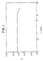
- An alloy layer of 3 ⁇ m in thickness having the composition of Fe93Cr 0.5 Ru1B 5.5 was produced in the same manner as in Example 1 and heated at 350°C for 1 hour in a rotating magnetic field and then cooled to room temperature at a cooling rate of 5°C/min. After that, it was measured with respect to the dependency of its effective permeability ⁇ e on frequency.
- Fig. 1 shows the dependency of its effective permeability on frequency. It is clear from Fig. 1 that the alloy layer of the present invention had high effective permeability at a high frequency region, so that it is suitable for magnetic heads.
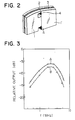
- a magnetic head having a structure shown in Fig. 2 was produced.
- 1, 1′ denote Fotoceram substrate cores, 2 a magnetic gap, 3 a laminated alloy layer and 4 bonding glass.
- the laminated alloy layer 3 contained alloy layers of the composition of Fe 91.9 Ru2B 6.1 .
- recording and reproducing characteristics for a metal tape was measured. The results are shown in Fig. 3, in which A denotes the magnetic head of the present invention and B that made of ferrite.
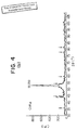
- amorphous alloy layer of 3 ⁇ m in thickness having the composition (by atomic %) consisting of 72.5%, Fe, 0.9% Cu, 3.2% Nb, 10.8% Si and 12.6% B was produced in the same manner as in Example 1.
- the resulting alloy layer was measured by X-ray diffraction.
- a halo pattern peculiar to an amorphous alloy was obtained as shown in Fig. 4 (a).
- peaks shown by arrows are those from the substrate, not from the alloy layer.
- this amorphous alloy layer was heat-treated at 530°C for 30 minutes in an N2 gas atmosphere and then cooled to room temperature.
- the X-ray diffraction measurement was conducted. As a result, the halo pattern almost disappeared while crystal peaks appeared as shown in Fig. 4 (b).
- As a result of observation by a transmission electron microscope at least 50% of the alloy structure was occupied by fine crystalline particles each having a maximum diameter of 100-200 ⁇ . It was confirmed by X-ray diffraction that these crystalline particles were composed of an Fe solid solution having a bcc structure.
- this alloy layer was measured by a vibration-type magnetometer (VSM) to know its hyteresis curve.
- VSM vibration-type magnetometer
- Bs was 13.2 kG
- Hc was 1.0 Oe.
- the effective permeability ⁇ e 1M at 1MHz was also measured by an LCR meter.
- ⁇ e 1M was 1200.
- the alloy layers of the present invention are superior to an Fe-Si-Al alloy layer in a saturation magnetic flux density, and that with respect to permeability ⁇ e 1M , both layers are substantially equivalent.
- the saturation magnetic flux densities of the alloy layers of the present invention are lower than that of an Fe-Si alloy layer, but their effective permeability ⁇ e 1M is much higher that of the Fe-Si alloy layer. Therefore, the alloy layer of the present invention can provide magnetic heads suitable for high-coercivity recording media.
- the alloy layers of the present invention had saturation magnetic flux densities Bs of 10 kG or more and saturation magnetostriction ⁇ s close to 0. Accordingly, they are less susceptible to strain which may be caused by the difference in a thermal expansion coefficient between the alloy layer and the substrate in the process of forming the alloy layer. Thus, magnetic heads produced by using such alloy layers suffer from substantially no deterioration of magnetic characteristics.
- the alloy layers for the magnetic heads of the present invention showed corrosion resistance higher than that of the conventional Fe-base alloy layers, and particularly those containing Cr, platinum-group elements, Nb or Ti showed excellent corrosion resistance. Incidentally, they had effective permeability exceeding 1000 at 1MHz.
- Each alloy layer of 15 ⁇ m in thickness having the composition shown in Table 8 was produced on the model head in the same manner as in Example 7 and mounted in a tape recorder to conduct a wear test.
- the wear of each alloy layer after 50 hours under the conditions of 20°C and 90% RH is shown in Table 8.
- the Fe-base soft magnetic alloy layer of the present invention showed wear resistance equal to or higher than that of the conventional soft magnetic layers. Particularly those containing platinum-group elements or Cr, etc. underwent only slight wear.
- An amorphous alloy layer of 3 ⁇ m in thickness having the composition of Fe 73.2 Cu 1.1 Nb 3.2 Si 16.5 B 6.0 was produced in the same manner as in Example 7 and heat-treated at a temperature shown in Table 9 for 1 hour and then cooled to room temperature.
- saturation magnetostriction ⁇ s, coercive force Hc, and effective permeability ⁇ e 1M at 1MHz were measured. Also, the alloy layer pealed off from the substrate was observed by a transmission electron microscope. The results are shown in Table 9. Table 9 No.
- the transmission electron microscopic observation showed that 50% or more of the alloy structure was composed of fine crystalline particles having an average particle size of 100-200 ⁇ when heat-treated at a temperature of 500°C or more.
- Such alloy structure leads to extremely small magnetostriction ⁇ s and small coercive force Hc while increasing effective permeability ⁇ e 1M .
- the addition of Cu serves to increase ⁇ e 1M . Further, the transmission electron microscopic observation showed that 50% or more of the alloy structure of the alloy layer containing Cu had fine crystalline particles having an average particle size of 500 ⁇ or less.
- Nb serves to extremely increase ⁇ e 1M .
- the transmission electron microscopic observation showed that the alloy containing Nb had an alloy structure, at least 50% of which was composed of fine crystalline particles having an average particle size of 500 ⁇ or less.
- the alloy layer of the present invention showed only small deterioration of effective permeability even at a temperature exceeding 500°C. This means that glass bonding can be effectively conducted to provide highly reliable magnetic heads by using such alloy.
- the Co-Nb-Zr amorphous layer showed extremely deteriorated permeability because of crystallization, meaning that it imposes restrictions on the process of manufacturing magnetic heads.
- amorphous alloy layer of the present invention having a thickness of 3 ⁇ m and the composition of Fe 72.7 Cu 1.1 Nb 3.2 Si 16.5 B 6.5 was produced on a Fotoceram substrate and measured with respect to dependency of effective permeability on frequency. The results are shown in Fig. 5. Thus, it was confirmed that the alloy layer of the present invention had high permeability in a wide range of frequency and so is highly suitable for magnetic heads for VTRs and computer memories.
- a magnetic head having the structure shown in Fig. 2 was produced by using an alloy layer of Fe 69.9 Cu 1.2 Nb 5.2 Si 15.5 B 7.1 Ru 1.1 , and its recording-reproducing characteristics were evaluated. Similar results to those shown in Fig. 3 were obtained.
Landscapes
- Engineering & Computer Science (AREA)
- Chemical & Material Sciences (AREA)
- Manufacturing & Machinery (AREA)
- Materials Engineering (AREA)
- Mechanical Engineering (AREA)
- Metallurgy (AREA)
- Organic Chemistry (AREA)
- Soft Magnetic Materials (AREA)
- Magnetic Heads (AREA)
- Thin Magnetic Films (AREA)
Applications Claiming Priority (4)
| Application Number | Priority Date | Filing Date | Title |
|---|---|---|---|
| JP183877/87 | 1987-07-23 | ||
| JP62183876A JP2556863B2 (ja) | 1987-07-23 | 1987-07-23 | Fe基磁性合金膜 |
| JP183876/87 | 1987-07-23 | ||
| JP62183877A JPH07116563B2 (ja) | 1987-07-23 | 1987-07-23 | Fe基軟磁性合金 |
Publications (3)
| Publication Number | Publication Date |
|---|---|
| EP0300511A2 true EP0300511A2 (fr) | 1989-01-25 |
| EP0300511A3 EP0300511A3 (en) | 1990-03-07 |
| EP0300511B1 EP0300511B1 (fr) | 1993-03-17 |
Family
ID=26502142
Family Applications (1)
| Application Number | Title | Priority Date | Filing Date |
|---|---|---|---|
| EP88111983A Expired - Lifetime EP0300511B1 (fr) | 1987-07-23 | 1988-07-25 | Tête magnétique |
Country Status (4)
| Country | Link |
|---|---|
| US (1) | US4918555A (fr) |
| EP (1) | EP0300511B1 (fr) |
| KR (1) | KR920005044B1 (fr) |
| DE (1) | DE3879305T2 (fr) |
Cited By (7)
| Publication number | Priority date | Publication date | Assignee | Title |
|---|---|---|---|---|
| EP0382195A1 (fr) * | 1989-02-08 | 1990-08-16 | Matsushita Electric Industrial Co., Ltd. | Tête magnétique et procédé pour fabriquer celle-ci |
| EP0455113A3 (en) * | 1990-04-24 | 1992-12-02 | Alps Electric Co., Ltd. | Fe based soft magnetic alloy, magnetic material containing same, and magnetic apparatus using the magnetic materials |
| EP0585782A3 (en) * | 1992-08-31 | 1994-05-18 | Aichi Steel Works Ltd | Composite magnetic component and method of manufacturing the same |
| EP0502535B1 (fr) * | 1991-03-06 | 1996-10-02 | Matsushita Electric Industrial Co., Ltd. | Tête magnétique |
| GB2405026A (en) * | 2003-08-13 | 2005-02-16 | Alps Electric Co Ltd | Thin film magnetic head including NiPRe alloy gap layer |
| EP1850334A1 (fr) * | 2006-04-27 | 2007-10-31 | Heraeus, Inc. | Souscouche magnétique douce dans moyen magnétique et cible de pulvérisation en alliage magnétique doux |
| CN109365241A (zh) * | 2018-08-31 | 2019-02-22 | 北京曙光航空电气有限责任公司 | 一种氧化镁薄膜转换涂液制备和使用方法 |
Families Citing this family (21)
| Publication number | Priority date | Publication date | Assignee | Title |
|---|---|---|---|---|
| US5225006A (en) * | 1988-05-17 | 1993-07-06 | Kabushiki Kaisha Toshiba | Fe-based soft magnetic alloy |
| US5051856A (en) * | 1988-10-14 | 1991-09-24 | Hitachi, Ltd. | Thin film magnetic head with mixed crystal structures |
| US5135818A (en) * | 1989-03-28 | 1992-08-04 | Hitachi Maxell, Ltd. | Thin soft magnetic film and method of manufacturing the same |
| JP2635422B2 (ja) * | 1989-10-17 | 1997-07-30 | アルプス電気株式会社 | 磁気ヘッド |
| CA2030446C (fr) * | 1989-11-22 | 2001-01-23 | Yoshihito Yoshizawa | Alliage magnetique a grains cristallins ultra fins |
| DE69018422T2 (de) * | 1989-12-28 | 1995-10-19 | Toshiba Kawasaki Kk | Auf Eisen basierende weichmagnetische Legierung, ihr Herstellungsverfahren und Magnetkern daraus. |
| US5173824A (en) * | 1990-12-07 | 1992-12-22 | Eastman Kodak Company | Magnetic head assembly |
| JP3357386B2 (ja) * | 1991-03-20 | 2002-12-16 | ティーディーケイ株式会社 | 軟磁性合金およびその製造方法ならびに磁心 |
| EP0531514B1 (fr) * | 1991-03-25 | 1996-08-28 | Eastman Kodak Company | Tete magnetique pour enregistrement a haute frequence et a haute densite |
| KR0130192B1 (ko) * | 1992-01-16 | 1998-04-17 | 가다오까 마사다까 | 자기헤드 및 그 제조방법 |
| US5636092A (en) * | 1992-07-31 | 1997-06-03 | Matsushita Electric Industrial Co., Ltd. | Magnetic head having chromium nitride protective film for use in magnetic recording and/or reproducing apparatus and method of manufacturing the same |
| JP3279399B2 (ja) * | 1992-09-14 | 2002-04-30 | アルプス電気株式会社 | Fe基軟磁性合金の製造方法 |
| US5485332A (en) * | 1992-11-30 | 1996-01-16 | Minebea Co., Ltd. | Floating magnetic head having a chamfered magnetic head core |
| EP0602486B1 (fr) * | 1992-12-14 | 1999-02-10 | Minebea Co.,Ltd. | Tête magnétique flottante |
| US5411813A (en) * | 1993-04-08 | 1995-05-02 | Eastman Kodak Company | Ferhgasi soft magnetic materials for inductive magnetic heads |
| JP3231149B2 (ja) * | 1993-07-30 | 2001-11-19 | アルプス電気株式会社 | ノイズフィルタ |
| JP2961034B2 (ja) * | 1993-09-16 | 1999-10-12 | アルプス電気株式会社 | 磁気ヘッド |
| US5935347A (en) * | 1993-12-28 | 1999-08-10 | Alps Electric Co., Ltd. | FE-base soft magnetic alloy and laminated magnetic core by using the same |
| JPH09256122A (ja) * | 1996-03-19 | 1997-09-30 | Unitika Ltd | Fe系非晶質合金 |
| CN101549360B (zh) * | 2009-04-03 | 2010-08-25 | 北京工业大学 | 一种高硼铸造合金导卫及其热处理方法 |
| CN112921244B (zh) * | 2021-01-22 | 2021-11-23 | 中国科学院合肥物质科学研究院 | 一种兼具高阻尼和零磁致伸缩特性的Fe-Ga基合金及其制备方法 |
Family Cites Families (9)
| Publication number | Priority date | Publication date | Assignee | Title |
|---|---|---|---|---|
| JPS5812120A (ja) * | 1981-07-10 | 1983-01-24 | Sony Corp | 磁気ヘツドの製造方法 |
| JPS5828341A (ja) * | 1981-07-20 | 1983-02-19 | Fuji Xerox Co Ltd | 誘電体フイルムの接合方法 |
| US4608297A (en) * | 1982-04-21 | 1986-08-26 | Showa Denka Kabushiki Kaisha | Multilayer composite soft magnetic material comprising amorphous and insulating layers and a method for manufacturing the core of a magnetic head and a reactor |
| US4483724A (en) * | 1982-09-27 | 1984-11-20 | Allied Corporation | Iron-boron solid solution alloys having high saturation magnetization and low magnetostriction |
| JPS6074104A (ja) * | 1983-09-29 | 1985-04-26 | Alps Electric Co Ltd | デジタル用磁気ヘツド |
| EP0144150B2 (fr) * | 1983-11-02 | 1991-01-23 | Hitachi, Ltd. | Matière ferromagnétique, matière ferromagnétique divisée en lamelles et tête magnétique |
| KR940004986B1 (ko) * | 1984-08-27 | 1994-06-09 | 가부시기가이샤 히다찌세이사꾸쇼 | 자성막의 제조방법 및 그것을 사용한 자기헤드 |
| EP0198422B1 (fr) * | 1985-04-11 | 1991-08-28 | Sony Corporation | Film mince magnétiquement doux |
| JP2516908B2 (ja) * | 1985-10-28 | 1996-07-24 | 松下電器産業株式会社 | 磁性ヘッドとその製造方法 |
-
1988
- 1988-07-23 KR KR8809324A patent/KR920005044B1/ko not_active Expired
- 1988-07-25 DE DE8888111983T patent/DE3879305T2/de not_active Expired - Fee Related
- 1988-07-25 US US07/223,843 patent/US4918555A/en not_active Expired - Fee Related
- 1988-07-25 EP EP88111983A patent/EP0300511B1/fr not_active Expired - Lifetime
Cited By (11)
| Publication number | Priority date | Publication date | Assignee | Title |
|---|---|---|---|---|
| EP0382195A1 (fr) * | 1989-02-08 | 1990-08-16 | Matsushita Electric Industrial Co., Ltd. | Tête magnétique et procédé pour fabriquer celle-ci |
| US5084795A (en) * | 1989-02-08 | 1992-01-28 | Matsushita Electric Industrial Co., Ltd. | Magnetic head and method of manufacturing the same |
| EP0455113A3 (en) * | 1990-04-24 | 1992-12-02 | Alps Electric Co., Ltd. | Fe based soft magnetic alloy, magnetic material containing same, and magnetic apparatus using the magnetic materials |
| EP0502535B1 (fr) * | 1991-03-06 | 1996-10-02 | Matsushita Electric Industrial Co., Ltd. | Tête magnétique |
| EP0585782A3 (en) * | 1992-08-31 | 1994-05-18 | Aichi Steel Works Ltd | Composite magnetic component and method of manufacturing the same |
| US5468522A (en) * | 1992-08-31 | 1995-11-21 | Aichi Steel Works, Ltd. | Method of manufacturing a composite magnetic component |
| GB2405026A (en) * | 2003-08-13 | 2005-02-16 | Alps Electric Co Ltd | Thin film magnetic head including NiPRe alloy gap layer |
| GB2405026B (en) * | 2003-08-13 | 2006-08-16 | Alps Electric Co Ltd | Thin film magnetic head including NiPre alloy gap layer |
| US7359148B2 (en) | 2003-08-13 | 2008-04-15 | Tdk Corporation | Thin film magnetic head including NiPRe alloy gap layer |
| EP1850334A1 (fr) * | 2006-04-27 | 2007-10-31 | Heraeus, Inc. | Souscouche magnétique douce dans moyen magnétique et cible de pulvérisation en alliage magnétique doux |
| CN109365241A (zh) * | 2018-08-31 | 2019-02-22 | 北京曙光航空电气有限责任公司 | 一种氧化镁薄膜转换涂液制备和使用方法 |
Also Published As
| Publication number | Publication date |
|---|---|
| US4918555A (en) | 1990-04-17 |
| EP0300511A3 (en) | 1990-03-07 |
| DE3879305T2 (de) | 1993-06-24 |
| KR890002821A (ko) | 1989-04-11 |
| KR920005044B1 (en) | 1992-06-25 |
| EP0300511B1 (fr) | 1993-03-17 |
| DE3879305D1 (de) | 1993-04-22 |
Similar Documents
| Publication | Publication Date | Title |
|---|---|---|
| EP0300511B1 (fr) | Tête magnétique | |
| KR910003977B1 (ko) | Fe-기본 연질 자성합금 및 이의 제조방법 | |
| US5484491A (en) | Ferromagnetic film | |
| JPWO2001093286A1 (ja) | 磁性薄膜、その製造方法、その評価方法及びこれを用いた磁気ヘッド、磁気記録装置並びに磁気デバイス | |
| US5302469A (en) | Soft magnetic thin film | |
| JP3970610B2 (ja) | 磁性薄膜および記録ヘッド | |
| US20030211360A1 (en) | Film and method for producing the same | |
| JPWO2001039219A1 (ja) | 磁性薄膜、磁性薄膜成膜方法、および記録ヘッド | |
| JPH07116563B2 (ja) | Fe基軟磁性合金 | |
| US5475554A (en) | Magnetic head using specified Fe Ta N Cu or Fe Ta N Ag alloy film | |
| JP2950917B2 (ja) | 軟磁性薄膜 | |
| KR900007666B1 (ko) | 자기헤드용 비정질 합금 | |
| EP0502535B1 (fr) | Tête magnétique | |
| JP2556863B2 (ja) | Fe基磁性合金膜 | |
| JP3058675B2 (ja) | 超微結晶磁性合金 | |
| JP2774702B2 (ja) | 軟磁性薄膜およびそれを用いた薄膜磁気ヘッド | |
| JP2771674B2 (ja) | 軟磁性合金膜 | |
| JP2657710B2 (ja) | 軟磁性薄膜の製造方法 | |
| JP2508462B2 (ja) | 軟磁性薄膜 | |
| JP2774708B2 (ja) | 軟磁性薄膜およびそれを用いた薄膜磁気ヘッド | |
| JP2584687B2 (ja) | 軟磁性薄膜の製造方法 | |
| JP2522284B2 (ja) | 軟磁性薄膜 | |
| JPH0758647B2 (ja) | 結晶質軟磁性薄膜 | |
| JPH08241813A (ja) | 磁気ヘッド用軟磁性薄膜材料 | |
| JPS61243144A (ja) | 磁気ヘツド用非晶質合金 |
Legal Events
| Date | Code | Title | Description |
|---|---|---|---|
| PUAI | Public reference made under article 153(3) epc to a published international application that has entered the european phase |
Free format text: ORIGINAL CODE: 0009012 |
|
| AK | Designated contracting states |
Kind code of ref document: A2 Designated state(s): DE FR GB |
|
| PUAL | Search report despatched |
Free format text: ORIGINAL CODE: 0009013 |
|
| AK | Designated contracting states |
Kind code of ref document: A3 Designated state(s): DE FR GB |
|
| RHK1 | Main classification (correction) |
Ipc: H01F 10/14 |
|
| 17P | Request for examination filed |
Effective date: 19900427 |
|
| 17Q | First examination report despatched |
Effective date: 19920416 |
|
| RAP1 | Party data changed (applicant data changed or rights of an application transferred) |
Owner name: HITACHI METALS, LTD. |
|
| GRAA | (expected) grant |
Free format text: ORIGINAL CODE: 0009210 |
|
| AK | Designated contracting states |
Kind code of ref document: B1 Designated state(s): DE FR GB |
|
| REF | Corresponds to: |
Ref document number: 3879305 Country of ref document: DE Date of ref document: 19930422 |
|
| ET | Fr: translation filed | ||
| K2C2 | Correction of patent specification (partial reprint) published |
Effective date: 19930317 |
|
| PLBE | No opposition filed within time limit |
Free format text: ORIGINAL CODE: 0009261 |
|
| STAA | Information on the status of an ep patent application or granted ep patent |
Free format text: STATUS: NO OPPOSITION FILED WITHIN TIME LIMIT |
|
| 26N | No opposition filed | ||
| PGFP | Annual fee paid to national office [announced via postgrant information from national office to epo] |
Ref country code: FR Payment date: 19960709 Year of fee payment: 9 |
|
| PGFP | Annual fee paid to national office [announced via postgrant information from national office to epo] |
Ref country code: GB Payment date: 19960716 Year of fee payment: 9 |
|
| PGFP | Annual fee paid to national office [announced via postgrant information from national office to epo] |
Ref country code: DE Payment date: 19960802 Year of fee payment: 9 |
|
| PG25 | Lapsed in a contracting state [announced via postgrant information from national office to epo] |
Ref country code: GB Free format text: LAPSE BECAUSE OF NON-PAYMENT OF DUE FEES Effective date: 19970725 |
|
| GBPC | Gb: european patent ceased through non-payment of renewal fee |
Effective date: 19970725 |
|
| PG25 | Lapsed in a contracting state [announced via postgrant information from national office to epo] |
Ref country code: FR Free format text: LAPSE BECAUSE OF NON-PAYMENT OF DUE FEES Effective date: 19980331 |
|
| PG25 | Lapsed in a contracting state [announced via postgrant information from national office to epo] |
Ref country code: DE Free format text: LAPSE BECAUSE OF NON-PAYMENT OF DUE FEES Effective date: 19980401 |
|
| REG | Reference to a national code |
Ref country code: FR Ref legal event code: ST |