EP0602486B1 - Tête magnétique flottante - Google Patents
Tête magnétique flottante Download PDFInfo
- Publication number
- EP0602486B1 EP0602486B1 EP93119594A EP93119594A EP0602486B1 EP 0602486 B1 EP0602486 B1 EP 0602486B1 EP 93119594 A EP93119594 A EP 93119594A EP 93119594 A EP93119594 A EP 93119594A EP 0602486 B1 EP0602486 B1 EP 0602486B1
- Authority
- EP
- European Patent Office
- Prior art keywords
- slider
- spacer
- head core
- head
- floating
- Prior art date
- Legal status (The legal status is an assumption and is not a legal conclusion. Google has not performed a legal analysis and makes no representation as to the accuracy of the status listed.)
- Expired - Lifetime
Links
- 238000007667 floating Methods 0.000 title claims description 45
- 125000006850 spacer group Chemical group 0.000 claims description 34
- 239000000126 substance Substances 0.000 claims description 14
- 239000011521 glass Substances 0.000 description 13
- 230000004927 fusion Effects 0.000 description 4
- 239000010409 thin film Substances 0.000 description 4
- 238000004804 winding Methods 0.000 description 4
- 238000004519 manufacturing process Methods 0.000 description 3
- 239000000919 ceramic Substances 0.000 description 2
- 238000010276 construction Methods 0.000 description 2
- 238000000280 densification Methods 0.000 description 2
- 238000000227 grinding Methods 0.000 description 2
- 238000000034 method Methods 0.000 description 2
- 238000004544 sputter deposition Methods 0.000 description 2
- 229910000859 α-Fe Inorganic materials 0.000 description 2
- 239000002131 composite material Substances 0.000 description 1
- 238000005516 engineering process Methods 0.000 description 1
- 238000005530 etching Methods 0.000 description 1
- 238000003754 machining Methods 0.000 description 1
- 239000000696 magnetic material Substances 0.000 description 1
- 238000000992 sputter etching Methods 0.000 description 1
Images


Classifications
-
- G—PHYSICS
- G11—INFORMATION STORAGE
- G11B—INFORMATION STORAGE BASED ON RELATIVE MOVEMENT BETWEEN RECORD CARRIER AND TRANSDUCER
- G11B5/00—Recording by magnetisation or demagnetisation of a record carrier; Reproducing by magnetic means; Record carriers therefor
- G11B5/10—Structure or manufacture of housings or shields for heads
- G11B5/105—Mounting of head within housing or assembling of head and housing
-
- G—PHYSICS
- G11—INFORMATION STORAGE
- G11B—INFORMATION STORAGE BASED ON RELATIVE MOVEMENT BETWEEN RECORD CARRIER AND TRANSDUCER
- G11B5/00—Recording by magnetisation or demagnetisation of a record carrier; Reproducing by magnetic means; Record carriers therefor
- G11B5/10—Structure or manufacture of housings or shields for heads
- G11B5/11—Shielding of head against electric or magnetic fields
-
- G—PHYSICS
- G11—INFORMATION STORAGE
- G11B—INFORMATION STORAGE BASED ON RELATIVE MOVEMENT BETWEEN RECORD CARRIER AND TRANSDUCER
- G11B5/00—Recording by magnetisation or demagnetisation of a record carrier; Reproducing by magnetic means; Record carriers therefor
- G11B5/127—Structure or manufacture of heads, e.g. inductive
- G11B5/17—Construction or disposition of windings
Definitions
- the present invention relates to a magnetic floating head used in a magnetic disk unit for computers or the like.
- Fig. 7 shows a composite type floating magnetic head 1 used in a magnetic disk unit for computers.
- the floating magnetic head 1 has a nearly rectangular slider 2 made from a nonmagnetic substance.
- Rails (floating surfaces) 3 for generating a floating force are provided on the upper portion, i.e. on the surface which faces a magnetic recording medium, of the slider 2.
- a groove 5 for winding coils which extends in the direction of width of the slider 2 is created on the side of air outflow ends 4, also called trailing ends 4, of the slider 2.
- a slit 6 which extends in the longitudinal direction of the rail 3 is created on a part of one rail 3 on the the air outflow end 4 side of the slider 2.
- the reference numeral 10 denote air inflow ends, also called leading ends, of the slider 2.
- JP-A-01 276421 discloses another floating magnetic head having a slider body composed of a non-magnetic material and having a cut channel formed on the side surface of the slider boy, the magnetic head core being fused and fixed by a transparent bonding glass in the channel.
- FIG. 1 through 6 a floating magnetic head of the present invention will be explained in detail.
- the same reference numerals are designated to the same members or same parts with those shown in Fig. 7 and explanation thereof will be omitted at times.
- a floating magnetic head according to a first embodiment will be explained.
- the floating magnetic head 1 comprises in outline a nearly rectangular slider 2 made from a magnetic substance such as ferrite and having a floating surface that faces to a magnetic recording medium on one surface thereof, a head core 9 located and provided on a side portion 2a on the side of an air outflow end 4 of the slider 2 and having a recording and playback gap 7 and a spacer 11 made from a nonmagnetic substance such as ceramics and interposed between the slider 2 and the head core 9.
- a notch 12 for the spacer which is longer than the head core 9 is created on the side portion 2a on the side of air outflow end 4 of the slider 2.
- the spacer 11 which is longer than the head core 9 is stored in the notch 12.
- a spacer side notch 13 which joins with a groove 5 for winding coils created in the slider 2 is created.
- Coils 8 are wound around core portions 9a and 9b respectively on the air outflow end side and on the air inflow end side of the head core 9 in a manner positioning them around the groove 5 and notch 13. Both coils 8 are connected and wound in a balancing manner. The coils 8 are wound so that they do not contact with the slider 2.
- the notch 12 for the spacer is created on the side portion 2a on the side of the air outflow end 4 of the slider 2 as shown in Fig. 2, the spacer 11 is bonded to this notch 12 by high fusion point glass as shown in Fig. 3 and then the groove 5 for winding coils is created on the air outflow end 4 side of one rail 3 of the slider 2 in a manner allowing to wind the coils 8.
- the side portion 2a of the slider 2 and the spacer 11 are machined so that they share the same flat surface.
- the spacer 11 is machined so that its thickness lies between 0.050 mm and 0.075 mm.
- the head core 9 fabricated in a different process from that of the slider 2 is bonded with the spacer 11 bonded with the notch 12 of the slider 2 by low fusion point glass or the like.
- they were bonded by forming a glass thin film by a glass sputtering. Due to that, the glass thin film can be very thin.
- an inclined face 14 is created by diagonally grinding the head core 9 from the side not bonded with the slider 2 to adjust a track width Tw of the head core 9 appearing to the rail 3 to a predetermined size.
- an area of the nonmagnetic spacer 11 and head core 9 appearing to the rail 3 is very small as compare to that of the magnetic slider 2 appearing to the rail 3.
- the slider 2 is independent from the head core 9 in terms of a magnetic circuit because the nonmagnetic spacer 11 is interposed between the slider 2 and the head core 9. Further, a magnetic resistance of the slider 2 is small as compared to that of the head core 9 because the slider 2 is made from a magnetic substance. Due to that, a noise from an external magnetic field is shielded by the slider 2 and a recording accuracy of the head can be improved. Furthermore, because the coils 8 are wound to the head core 9 in a balancing manner, the external magnetic field can be canceled further.
- the magnetic recording medium will not be damaged by the edge 15 even when it is operated by a CSS (Contact Start Stop) system and thereby the resistance to CSS can be improved.
- a CSS Contact Start Stop
- the spacer 11 can be provided without increasing the size of the unit.
- Fig. 4 is a perspective view showing the floating magnetic head 1 according to a second embodiment of the present invention.
- a spacer 11 having a same length with that of the side portion 2a of the slider 2 is bonded with the side portion 2a of the slider 2 and the head core 9 is bonded with this spacer 11.
- the spacer 11 is fabricated so that its thickness lies between 0.050 mm and 0.075 mm.
- This floating magnetic head 1 can shield the noise of the external magnetic field by the magnetic slider 2 and because the coil 8 is wound around the head core 9 in the balancing manner, can cancel the external magnetic field further similarly to the floating magnetic head 1 in the first embodiment described above.
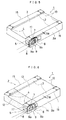
- Fig. 5 is a perspective view showing the floating magnetic head 1 according to a third embodiment of the present invention.
- the slider 2 of the floating magnetic head 1 of the first embodiment has the notch 12 for the spacer
- no notch is created on the slider 2 in the floating magnetic head 1 of the third embodiment. It is constructed by bonding the spacer 11 with the head core 9 beforehand and then by bonding the spacer 11 with which the head core 9 has been bonded with the side portion 2a of the slider 2.
- the spacer 11 is fabricated so that its thickness lies between 0.050 mm and 0.075 mm at this time.
- This floating magnetic head 1 can shield the noise of the external magnetic field by the magnetic slider 2 and because the coil 8 is wound around the head core 9 in the balancing manner, can cancel the external magnetic field further similarly to the floating magnetic head 1 in the first embodiment described above. Furthermore, because the step for creating a notch on the side portion 2a of the slider 2 is eliminated, the production manday can be reduced to that degree.
- Fig. 6 is a perspective view showing the floating magnetic head 1 according to a fourth embodiment of the present invention.
- the floating magnetic head 1 comprises a nearly rectangular slider 2 and a head core 9 having a recording and playback gap 7.
- the head core 9 is bonded with the side portion 2a of the slider 2 on the side of the air outflow end 4.
- the slider 2 is composed of a first slider block 12 made from a nonmagnetic substance such as ceramics provided in correspondence with a portion 11' bonded with the head core 9 and a second slider block 13 made from a magnetic substance such as ferrite provided in correspondence with the other portion excepting the portion 11' bonded with the head core 9.
- this floating magnetic head 1 will now be explained in detail along its manufacturing process.
- the first slider block 12 and the second slider block 13 are bonded by high fusion point glass to joint them.
- the aforementioned bonded first and second slider blocks 12 and 13 are cut into a desired slider width to obtain the slider 2.
- the groove 5 which allows to wind the coil 8 around the core portions 9a and 9b of the head core 9 on the side of air outflow end is created on the side of the air outflow end 4 of one rail 3 of the slider 2.
- the head core 9 fabricated in a different process from that of the slider 2 is bonded with the side portion 2a of the slider 2 by low fusion point glass or the like.
- they were bonded by forming a glass thin film by glass sputtering. Due to that, the glass thin film can be very thin.
- a distance between the recording and playback gap 7 and the second slider block 13 is separated so that it becomes greater than a width of the recording and playback gap 7 by more than 10 to 20 times by adjusting and setting the size of the first slider block 12 and the bonding position of the head core 9.
- an inclined face 14 is created by diagonally grinding the head core 9 from the side not bonded with the slider 2 to adjust a track width Tw of the head core 9 appearing to the rail 3 to a predetermined size (7 micron in the present embodiment).
- Such machining of the track width Tw of the head core 9 may be carried out using an etching technology such as ion milling.
- the head core 9 is chamfered from the both sides of air inflow end and air outflow end and is ground diagonally on the side of the floating surface to the size of the track width Tw, the portion of the head core 9 which appears to the rail 3 is only a small portion of the track width Tw.
- a magnetic resistance of the slider 2 is small as compare to that of the head core 9 because the most of the slider 2, i.e. the second slider block 13, is made from a magnetic substance. Due to that, the noise from the external magnetic field is shielded by the magnetic second slider block 13. Furthermore, because the recording and playback gap 7 and the second slider block 13 are separated by the distance 10 to 20 times of the width of the recording and playback gap 7, a magnetic field generated by the recording and playback gap 7 during recording is not influenced by the second slider block 13.
- a size of the first slider block 12 made from a non-magnetic substance is made to be larger than the head core 9 so that the core portion 9b of the head core 9 on the side of air inflow end does not contact with the magnetic second slider block 13.
- an area which appears to the rail 3 is mostly that of the second slider block 13 due to the fact that the area of the first slider block 12 and head core 9 appearing to the rail 3 is small as compare to that of the second slider block 13 appearing to the rail 3 and because the edge 15 of the slider 2 appearing to the rail 3 is chamfered, the magnetic recording medium will not be damaged by the edge 15 even when it is operated by a CSS (Contact Start Stop) system and thereby the resistance to CSS can be improved.
- a CSS Contact Start Stop
- the groove 5 for winding coils is created on the slider 2 on the side of the air outflow end 4 of one rail 3 in a manner allowing to wind the coils 8 around core portions 9a and 9b respectively on the air outflow end side and on the air inflow end side of the head core 9.
- the both coils 8 are connected and are wound in a balancing manner.
- the slider can be independent of the head core in terms of a magnetic circuit because the nonmagnetic spacer is interposed between the slider and the head core, and a magnetic resistance of the slider can be small as compare to that of the head core because the slider is made from a magnetic substance.
- the coil can be wound in a balancing manner around the core portions of the head core 9 respectively on the sides of the air outflow end and air inflow end in the state that the spacer is interposed between the slider and the head core.
- the spacer can be also interposed between the slider and the head core in a manner storing the spacer in a notch by creating the notch for storing the spacer on the slider.
- the portion of the slider bonded with the head core is made from a nonmagnetic substance and the other portion of the slider excepting that portion is made from a magnetic substance and because the later portion is made large, the most of the slider is dominated by the magnetic substance and its magnetic resistance can be small as compare to that of the head core.
Landscapes
- Engineering & Computer Science (AREA)
- Manufacturing & Machinery (AREA)
- Magnetic Heads (AREA)
- Adjustment Of The Magnetic Head Position Track Following On Tapes (AREA)
Claims (4)
- Tête magnétique flottante (1) comprenant :caractérisée :un coulisseau (2), sensiblement rectangulaire, comportant des extrémités de tête (10) et de queue (4), et pourvu d'une encoche (12) formée sur une partie latérale de ce coulisseau ;une rainure (5), formée sur l'extérieur du coulisseau (2) ;des rails (3) montés sur une face du coulisseau (2) qui fait face à un support d'enregistrement magnétique pour produire une force de flottement ;en ce que la profondeur de la rainure augmente graduellement le long d'une direction longitudinale du coulisseau et forme une ouverture à l'extrémité de queue (4) ;en ce que le coulisseau (2) est constitué d'une substance magnétique, un écarteur (11) réalisé en une substance non magnétique se trouvant sur l'encoche (12), qui est externe au rail (3) de ce coulisseau ;en ce qu'un noyau (9) de tête est lié à une surface extérieure de l'écarteur (11) et comporte des première et seconde jambes (9b, 9a), la seconde jambe (9a) étant située à l'extrémité de queue (4) du coulisseau (2) sans faire saillie par rapport à l'extrémité de queue de façon que la première jambe (9b) soit située entre la seconde jambe (9a) et l'extrémité de tête (10) du coulisseau ; eten ce que la longueur de l'écarteur (11), mesurée dans la direction longitudinale du coulisseau (2), est plus grande que la longueur du noyau (9) de tête, mesurée dans la direction longitudinale du coulisseau, la longueur de la rainure (5), mesurée dans cette direction longitudinale étant plus grande que la longueur du noyau (9) de tête mesurée dans cette direction.
- Tête magnétique flottante selon la revendication 1, dans laquelle la longueur de l'écarteur (11), mesurée dans la direction longitudinale du coulisseau, est égale à la longueur de ce coulisseau (2), mesurée dans cette direction.
- Tête magnétique flottante selon les revendications 1 à 2, dans laquelle le noyau (9) de tête comporte une face inclinée (14) sur un côté opposé au côté qui est lié à la surface extérieure de l'écarteur.
- Tête magnétique flottante selon les revendications 1 à 3, dans laquelle des bobines (8) sont enroulées, d'une manière équilibrée, autour des jambes (9a, 9b) du noyau (9) de tête.
Applications Claiming Priority (4)
| Application Number | Priority Date | Filing Date | Title |
|---|---|---|---|
| JP353664/92 | 1992-12-14 | ||
| JP35366492A JP2818994B2 (ja) | 1992-12-14 | 1992-12-14 | 浮動磁気ヘッド |
| JP35965992A JP2879184B2 (ja) | 1992-12-25 | 1992-12-25 | 浮動磁気ヘッド |
| JP359659/92 | 1992-12-25 |
Publications (3)
| Publication Number | Publication Date |
|---|---|
| EP0602486A2 EP0602486A2 (fr) | 1994-06-22 |
| EP0602486A3 EP0602486A3 (en) | 1995-08-23 |
| EP0602486B1 true EP0602486B1 (fr) | 1999-02-10 |
Family
ID=26579892
Family Applications (1)
| Application Number | Title | Priority Date | Filing Date |
|---|---|---|---|
| EP93119594A Expired - Lifetime EP0602486B1 (fr) | 1992-12-14 | 1993-12-06 | Tête magnétique flottante |
Country Status (3)
| Country | Link |
|---|---|
| US (1) | US5548459A (fr) |
| EP (1) | EP0602486B1 (fr) |
| DE (1) | DE69323480T2 (fr) |
Families Citing this family (4)
| Publication number | Priority date | Publication date | Assignee | Title |
|---|---|---|---|---|
| JPH0954931A (ja) * | 1995-08-09 | 1997-02-25 | Minebea Co Ltd | 浮動型磁気ヘッド及びその製造方法 |
| US5997755A (en) * | 1997-09-30 | 1999-12-07 | Yamaha Corporation | Damage-reduced magnetic head |
| US6535353B2 (en) * | 1998-03-20 | 2003-03-18 | Seagate Technology Llc | Capped polymeric load/unload pads |
| JP4008654B2 (ja) * | 2000-11-29 | 2007-11-14 | 新科實業有限公司 | 薄膜磁気ヘッドおよびその製造方法 |
Family Cites Families (38)
| Publication number | Priority date | Publication date | Assignee | Title |
|---|---|---|---|---|
| US3229268A (en) * | 1961-04-28 | 1966-01-11 | Burroughs Corp | Detachable electromagnetic air bearing transducer |
| US3956771A (en) * | 1975-03-03 | 1976-05-11 | Honeywell Information Systems, Inc. | Magnetic transducer with side mounted ferrite core and method of making the same |
| JPS54151427A (en) * | 1978-05-19 | 1979-11-28 | Fujitsu Ltd | Production of magnetic head |
| JPS55146630A (en) * | 1979-04-30 | 1980-11-15 | Nec Corp | Magnetic head |
| JPS56114115A (en) * | 1980-02-12 | 1981-09-08 | Canon Inc | Magnetic head |
| JPS57155339A (en) * | 1981-03-20 | 1982-09-25 | Matsushita Electric Ind Co Ltd | Magnetic head and production thereof |
| US4711018A (en) * | 1984-01-14 | 1987-12-08 | Ngk Insulators, Ltd. | Method of manufacturing a magnetic head core |
| JPS60150615U (ja) * | 1984-03-14 | 1985-10-07 | シチズン時計株式会社 | 磁気記録ヘツド |
| JPS61184705A (ja) * | 1985-02-13 | 1986-08-18 | Hitachi Ltd | 磁気ヘツド |
| JPS6275927A (ja) * | 1985-09-27 | 1987-04-07 | Alps Electric Co Ltd | 浮動式磁気ヘツドおよびその製造方法 |
| US4894742A (en) * | 1985-10-07 | 1990-01-16 | Nippon Mining Company, Limited | Thin-film laminated magnetic heads of Fe-Si-Al alloy |
| JPS62180516A (ja) * | 1986-02-03 | 1987-08-07 | Alps Electric Co Ltd | 浮動式磁気ヘツド |
| US4870520A (en) * | 1986-05-29 | 1989-09-26 | Magnetic Peripherals Inc. | Read/write head with side winding slot |
| JPS63292410A (ja) * | 1987-05-25 | 1988-11-29 | Nec Corp | 磁気ヘッド |
| JPS63292413A (ja) * | 1987-05-25 | 1988-11-29 | Sony Corp | 浮上型磁気ヘッド |
| KR920005044B1 (en) * | 1987-07-23 | 1992-06-25 | Hitachi Ltd | Magnetic head |
| JPS6450217A (en) * | 1987-08-21 | 1989-02-27 | Seiko Epson Corp | Composite type magnetic head |
| JPH01211211A (ja) * | 1988-02-18 | 1989-08-24 | Matsushita Electric Ind Co Ltd | 複合型浮動磁気ヘッド |
| JPH01260606A (ja) * | 1988-04-12 | 1989-10-17 | Matsushita Electric Ind Co Ltd | 浮動型磁気ヘッド |
| JPH01276421A (ja) * | 1988-04-27 | 1989-11-07 | Seiko Epson Corp | 磁気ヘッド |
| US4870521A (en) * | 1988-06-23 | 1989-09-26 | Kyocera Corporation | Floating magnetic head |
| JPH02201714A (ja) * | 1989-01-31 | 1990-08-09 | Pioneer Electron Corp | 磁気ヘッド |
| JPH02232803A (ja) * | 1989-03-06 | 1990-09-14 | Nec Corp | 磁気ヘッド |
| JPH02270111A (ja) * | 1989-04-12 | 1990-11-05 | Seiko Epson Corp | 複合型浮動磁気ヘッドの構造 |
| JPH0319119A (ja) * | 1989-06-16 | 1991-01-28 | Nec Kansai Ltd | 浮動型磁気ヘッド |
| JP2972889B2 (ja) * | 1989-06-29 | 1999-11-08 | ティーディーケイ株式会社 | 浮上型磁気ヘッド |
| JPH0349019A (ja) * | 1989-07-18 | 1991-03-01 | Seiko Epson Corp | 複合浮動型磁気ヘッド |
| JPH03125320A (ja) * | 1989-10-11 | 1991-05-28 | Nec Kansai Ltd | 浮動型磁気ヘッド |
| JPH03209617A (ja) * | 1990-01-11 | 1991-09-12 | Matsushita Electric Ind Co Ltd | 磁気ヘッド及びその製造方法 |
| JPH03272004A (ja) * | 1990-03-20 | 1991-12-03 | Nec Kansai Ltd | 磁気ヘッド |
| JPH0782629B2 (ja) * | 1990-03-23 | 1995-09-06 | 日本碍子株式会社 | 固定磁気ディスク装置用コアスライダ及びその製造方法 |
| JPH043308A (ja) * | 1990-04-19 | 1992-01-08 | Hitachi Metals Ltd | 浮上型磁気ヘッド |
| JPH0428010A (ja) * | 1990-05-24 | 1992-01-30 | Kyocera Corp | 複合型浮上磁気ヘッドおよびその製造方法 |
| JPH04222916A (ja) * | 1990-12-26 | 1992-08-12 | Victor Co Of Japan Ltd | 磁気記録再生ヘッド装置及び記録再生方法 |
| JPH05182137A (ja) * | 1991-12-09 | 1993-07-23 | Nikko Kyodo Co Ltd | 浮上型磁気ヘッドの製造方法 |
| JP2855390B2 (ja) * | 1992-08-28 | 1999-02-10 | ミネベア株式会社 | 浮動磁気ヘッド |
| JP2952455B2 (ja) * | 1992-10-30 | 1999-09-27 | ミネベア株式会社 | 浮動磁気ヘッド |
| US5485332A (en) * | 1992-11-30 | 1996-01-16 | Minebea Co., Ltd. | Floating magnetic head having a chamfered magnetic head core |
-
1993
- 1993-12-06 DE DE69323480T patent/DE69323480T2/de not_active Expired - Fee Related
- 1993-12-06 EP EP93119594A patent/EP0602486B1/fr not_active Expired - Lifetime
-
1995
- 1995-02-21 US US08/390,947 patent/US5548459A/en not_active Expired - Fee Related
Also Published As
| Publication number | Publication date |
|---|---|
| EP0602486A3 (en) | 1995-08-23 |
| DE69323480D1 (de) | 1999-03-25 |
| EP0602486A2 (fr) | 1994-06-22 |
| DE69323480T2 (de) | 1999-06-24 |
| US5548459A (en) | 1996-08-20 |
Similar Documents
| Publication | Publication Date | Title |
|---|---|---|
| US4979051A (en) | Bimodal multi-track magnetic head | |
| JPS6341127B2 (fr) | ||
| US5546251A (en) | Floating magnetic head having a magnetic head core with a balanced winding bonded to a slider side surface | |
| EP0602486B1 (fr) | Tête magnétique flottante | |
| EP0139018B1 (fr) | Assemblage de têtes transductrices magnétiques d'un seul type de pôles magnétiques pour enregistrement perpendiculaire | |
| US4768121A (en) | Magnetic head formed by composite main pole film and winding core for perpendicular magnetic recording | |
| US5276578A (en) | Magnetic head having a pair of front core assemblies | |
| KR900004743B1 (ko) | 수직 자기기록용 자기헤드 및 그 제조방법 | |
| US5485332A (en) | Floating magnetic head having a chamfered magnetic head core | |
| US5267107A (en) | Laminated magnetic transducer | |
| JPS59215022A (ja) | 磁気ヘツド製造法 | |
| JPS634244B2 (fr) | ||
| JP2879184B2 (ja) | 浮動磁気ヘッド | |
| JPS6275927A (ja) | 浮動式磁気ヘツドおよびその製造方法 | |
| JPS634243B2 (fr) | ||
| JP2546826B2 (ja) | コンポジット型磁気ヘツドの製造方法 | |
| JP2545304B2 (ja) | 浮上型磁気ヘッド | |
| JPS6111911A (ja) | 磁気ヘツド装置 | |
| JP2659634B2 (ja) | 磁気消去ヘッド及びその製造方法 | |
| JPH0546009B2 (fr) | ||
| JPS61289513A (ja) | 磁気ヘツド | |
| JPH0366009A (ja) | 磁気ヘッドの製造方法 | |
| JPH064821A (ja) | 磁気ヘッド及びその製造方法 | |
| JPH10255218A (ja) | 磁気ヘッド及びその製造方法 | |
| JPS6379203A (ja) | 磁気ヘツドおよびその製造方法 |
Legal Events
| Date | Code | Title | Description |
|---|---|---|---|
| PUAI | Public reference made under article 153(3) epc to a published international application that has entered the european phase |
Free format text: ORIGINAL CODE: 0009012 |
|
| AK | Designated contracting states |
Kind code of ref document: A2 Designated state(s): DE FR GB |
|
| RIN1 | Information on inventor provided before grant (corrected) |
Inventor name: TAKAYANAGI, KAZUTOSHI, C/O MINEBEA CO., LTD. Inventor name: SANO, AKINOBU, C/O MINEBEA CO., LTD. Inventor name: FUJITA, TETSUJI, C/O MINEBEA CO., LTD. Inventor name: EGAWA, MOTOJI, C/O MINEBEA CO., LTD. |
|
| PUAL | Search report despatched |
Free format text: ORIGINAL CODE: 0009013 |
|
| AK | Designated contracting states |
Kind code of ref document: A3 Designated state(s): DE FR GB |
|
| 17P | Request for examination filed |
Effective date: 19951204 |
|
| 17Q | First examination report despatched |
Effective date: 19970718 |
|
| GRAG | Despatch of communication of intention to grant |
Free format text: ORIGINAL CODE: EPIDOS AGRA |
|
| GRAG | Despatch of communication of intention to grant |
Free format text: ORIGINAL CODE: EPIDOS AGRA |
|
| GRAH | Despatch of communication of intention to grant a patent |
Free format text: ORIGINAL CODE: EPIDOS IGRA |
|
| GRAH | Despatch of communication of intention to grant a patent |
Free format text: ORIGINAL CODE: EPIDOS IGRA |
|
| GRAA | (expected) grant |
Free format text: ORIGINAL CODE: 0009210 |
|
| AK | Designated contracting states |
Kind code of ref document: B1 Designated state(s): DE FR GB |
|
| REF | Corresponds to: |
Ref document number: 69323480 Country of ref document: DE Date of ref document: 19990325 |
|
| ET | Fr: translation filed | ||
| PGFP | Annual fee paid to national office [announced via postgrant information from national office to epo] |
Ref country code: DE Payment date: 19991125 Year of fee payment: 7 |
|
| PGFP | Annual fee paid to national office [announced via postgrant information from national office to epo] |
Ref country code: FR Payment date: 19991126 Year of fee payment: 7 |
|
| PGFP | Annual fee paid to national office [announced via postgrant information from national office to epo] |
Ref country code: GB Payment date: 19991129 Year of fee payment: 7 |
|
| PLBE | No opposition filed within time limit |
Free format text: ORIGINAL CODE: 0009261 |
|
| STAA | Information on the status of an ep patent application or granted ep patent |
Free format text: STATUS: NO OPPOSITION FILED WITHIN TIME LIMIT |
|
| 26N | No opposition filed | ||
| PG25 | Lapsed in a contracting state [announced via postgrant information from national office to epo] |
Ref country code: GB Free format text: LAPSE BECAUSE OF NON-PAYMENT OF DUE FEES Effective date: 20001206 |
|
| GBPC | Gb: european patent ceased through non-payment of renewal fee |
Effective date: 20001206 |
|
| PG25 | Lapsed in a contracting state [announced via postgrant information from national office to epo] |
Ref country code: FR Free format text: LAPSE BECAUSE OF NON-PAYMENT OF DUE FEES Effective date: 20010831 |
|
| REG | Reference to a national code |
Ref country code: FR Ref legal event code: ST |
|
| PG25 | Lapsed in a contracting state [announced via postgrant information from national office to epo] |
Ref country code: DE Free format text: LAPSE BECAUSE OF NON-PAYMENT OF DUE FEES Effective date: 20011002 |