EP0301537B1 - Appareil d'enregistrement/reproduction à carte optique - Google Patents
Appareil d'enregistrement/reproduction à carte optique Download PDFInfo
- Publication number
- EP0301537B1 EP0301537B1 EP88112227A EP88112227A EP0301537B1 EP 0301537 B1 EP0301537 B1 EP 0301537B1 EP 88112227 A EP88112227 A EP 88112227A EP 88112227 A EP88112227 A EP 88112227A EP 0301537 B1 EP0301537 B1 EP 0301537B1
- Authority
- EP
- European Patent Office
- Prior art keywords
- data
- data area
- card
- optical head
- detection means
- Prior art date
- Legal status (The legal status is an assumption and is not a legal conclusion. Google has not performed a legal analysis and makes no representation as to the accuracy of the status listed.)
- Expired - Lifetime
Links
Images



Classifications
-
- G—PHYSICS
- G11—INFORMATION STORAGE
- G11B—INFORMATION STORAGE BASED ON RELATIVE MOVEMENT BETWEEN RECORD CARRIER AND TRANSDUCER
- G11B7/00—Recording or reproducing by optical means, e.g. recording using a thermal beam of optical radiation by modifying optical properties or the physical structure, reproducing using an optical beam at lower power by sensing optical properties; Record carriers therefor
- G11B7/002—Recording, reproducing or erasing systems characterised by the shape or form of the carrier
- G11B7/0033—Recording, reproducing or erasing systems characterised by the shape or form of the carrier with cards or other card-like flat carriers, e.g. flat sheets of optical film
-
- G—PHYSICS
- G06—COMPUTING OR CALCULATING; COUNTING
- G06K—GRAPHICAL DATA READING; PRESENTATION OF DATA; RECORD CARRIERS; HANDLING RECORD CARRIERS
- G06K7/00—Methods or arrangements for sensing record carriers, e.g. for reading patterns
- G06K7/01—Details
- G06K7/016—Synchronisation of sensing process
-
- G—PHYSICS
- G11—INFORMATION STORAGE
- G11B—INFORMATION STORAGE BASED ON RELATIVE MOVEMENT BETWEEN RECORD CARRIER AND TRANSDUCER
- G11B17/00—Guiding record carriers not specifically of filamentary or web form, or of supports therefor
- G11B17/34—Guiding record carriers during transducing operation, e.g. for track following
-
- G—PHYSICS
- G11—INFORMATION STORAGE
- G11B—INFORMATION STORAGE BASED ON RELATIVE MOVEMENT BETWEEN RECORD CARRIER AND TRANSDUCER
- G11B19/00—Driving, starting, stopping record carriers not specifically of filamentary or web form, or of supports therefor; Control thereof; Control of operating function ; Driving both disc and head
- G11B19/20—Driving; Starting; Stopping; Control thereof
- G11B19/24—Arrangements for providing constant relative speed between record carrier and head
-
- G—PHYSICS
- G11—INFORMATION STORAGE
- G11B—INFORMATION STORAGE BASED ON RELATIVE MOVEMENT BETWEEN RECORD CARRIER AND TRANSDUCER
- G11B25/00—Apparatus characterised by the shape of record carrier employed but not specific to the method of recording or reproducing, e.g. dictating apparatus; Combinations of such apparatus
- G11B25/04—Apparatus characterised by the shape of record carrier employed but not specific to the method of recording or reproducing, e.g. dictating apparatus; Combinations of such apparatus using flat record carriers, e.g. disc, card
Definitions
- the present invention relates to an optical card recording/reproducing apparatus according to the preamble of claim 1.
- An optical card recording/reproducing apparatus of that kind is known from GB 2 174 531 A1 .
- This known apparatus comprises a card holding means for holding an optical card which comprises a data area in a center portion of the surface thereof.
- the surface of this optical card is irradiated by an optical head which projects a light beam onto the surface of the card.
- a moving means for providing a relative motion between the card holding means and the optical head.
- an optical card 11 has its one surface provided with an optical data recording section 13, which is divided into a plurality of parallel tracks 12 in the lengthwise direction of the card. Movement of optical card 11 with respect to a fixed optical head or movement of a movable optical head with respect to optical card 11 when it is of a fixed type causes tracks 12 to be scanned with a laser beam for data recording/reproducing.
- Each track 12 has its center portion serving as a data section 15, and two identifier (ID) sections 14a and 14b, on which the address of the track is recorded, are provided adjacent to both ends of the data section 15, respectively.
- ID sections 14a and 14b permit address readout in both lateral movements of card 11 with respect to the optical head.
- ID sections 14a and 14b are located at a given distance from the card's edge portions.
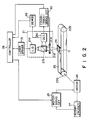
- Fig. 2 is a block diagram of the optical card recording/reproducing apparatus as disclosed in the aforementioned JP 61-178876 A1.
- a fixed optical head 21 scans a track with a laser beam while moving optical card 11 in the track direction so as to access data section 15 for data recording/reproducing.
- optical head 21 moves in she direction perpendicular to the tracks to be ready for recording/reproducing of the next track.
- a shuttle 24 is provided at a predetermined location on an endless conveyor belt 23 stretched over pulleys 22a and 22b.
- Optical card 11 is loaded in shuttle 24 with the card's lengthwise direction coinciding with the moving direction of the shuttle 24.
- optical card 11 is moved in its lengthwise direction.
- the belt 23 is driven by a motor 26 coupled to pulley 22a.
- motor 26 is rotated in the reverse direction.
- Motor 26 is provided with a rotary encoder 27 for detecting the amount and direction of its rotation, and the detection signal from this rotary encoder 27 is fed back to a motor-servo circuit 25.
- Optical head 21, which is located at a predetermined location above the path of shuttle 24 conveyed by belt 23, comprises a laser diode 21a, a half prism 21b, a detector 21c, an objective 21d and a lens actuator 21e.
- a laser beam from laser diode 21a is irradiated onto optical card 11 loaded in shuttle 24, through half prism 21b and objective 21d. Therefore, optical card 11 loaded in shuttle 24 is reciprocated about the laser beam irradiation point.
- the laser beam reflected at optical card 11 has the direction of its optical path changed 90° by half prism 21b and enters detector 21c.
- the output of detector 21c is supplied through a demodulator 29 to a controller 28 as reproduction data.
- Recorded data is modulated in a predetermined system using a self clock, and the demodulation system of demodulator 29 is associated with the modulation system.
- the output of detector 21c is also supplied to a focus/track-servo circuit 30, which drives lens actuator 21e in accordance with a command from controller 28 to control the focusing and tracking of objective 21d so that a laser beam is irradiated on the optical card 11 always in a focused state.
- Controller 28 controls laser diode 21a through a laser driver 31 to emit a laser beam whose intensity is modulated according to the level, "0" or “1,” of recording data at the time of data recording and emit a laser beam with a constant level (normally, "0" level in the data recording) at the time of data reproducing. Controller 28 also controls motor-servo circuit 25, demodulator 29 and focus/track-servo circuit 30 to seek a desired track based on the track data demodulated by demodulator 29.
- motorservo circuit 25 controls motor 26 based on the detection signal from rotary encoder 27 so that ID sections 14a and 14b and data section 15 of optical card 11 pass the beam irradiation point at a constant speed. This constant speed with respect to the laser beam at the time of data recording/reproducing is required due to the employment of the modulation system using the self clock.
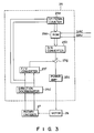
- Fig. 3 is a block diagram illustrating the arrangement of motor-servo circuit 25.
- This motor-servo circuit 25 comprises a read only memory (ROM) 25a, a digital to analog (D/A) converter 25b, a power amplifier 25c, a direction discriminator 25d, an up/down counter 25e, a frequency to voltage (F/V) converter 25f and a subtractor 25g.
- ROM read only memory
- D/A digital to analog
- F/V frequency to voltage
- ROM 25a has addresses which correspond to the individual points within the reciprocating range of card 11, and has target data of the conveying speed of shuttle 24 at those points stored at the respective addresses.
- Shuttle 24, before the start of the operation, is secured to its initial position, for example, one edge of shuttle 24 is at the beam irradiation point. Therefore, ROM 25a contains data which gradually accelerates shuttle 24 as the shuttle moves, sets shuttle 24 at a constant speed when the head of ID section 14a reaches the beam irradiation point, and gradually decelerates shuttle 24 when the end of ID section 14b passes the beam irradiation point.
- control signals such as a drive direction signal DIRC and drive signal DRIV, from controller 28 are supplied to ROM 25a, the address corresponding to the aforementioned initial position is set in ROM 25a.
- the speed target data read out from ROM 25a is subplied to motor 26 through D/A converter 25b, subtractor 25g and power amplifier 25c.
- Subtractor 25g is also supplied with a signal from rotary encoder 27 in order to provide a feedback control to set the rotational speed of motor 26 at the target level.
- D/A converter 25b The output of D/A converter 25b is supplied to a + terminal of subtractor 25g.
- Rotary encoder 27 which is coupled directly to the shaft of motor 26, outputs a phase A pulse signal and a phase B pulse signal, the order in which these pulses are generated is reversed depending on the rotational directions of motor 26 and which are supplied to direction discriminator 25d. Based on which one of the phases of the phase A and phase B signals is leading, direction discriminator 25d discriminates the moving direction of shuttle 24.
- Direction discriminator 25d affixes a plus or minus signal in accordance with the discriminated shuttle moving direction to either one of the phase A and B signals, and sends the resultant signal to F/V converter 25f where it is converted to a voltage signal corresponding to the conveying speed with the direction considered. This voltage signal is then supplied to a - terminal of subtractor 25g.
- Direction discriminator sends one of the above-mentioned phase A and B signals to an up count terminal or a down count terminal of up/down counter 25e in accordance with the discriminated shuttle moving direction. Consequently, the count value of up/down counter 25e is increased or decreased by the amount corresponding to the amount of rotation of motor 26. Accordingly, the address of ROM 25a is updated to be always correspond to the current position of shuttle 24 as measured from the initial position.
- shuttle 24 is gradually accelerated from the initial position, and is moved at a constant speed from the point where the head of ID section 14a reaches the beam irradiation point to a point where the end of ID section 14b passes the beam irradiation point, and is thereafter gradually decelerated to stop moving when it reaches pulley 22b.
- the relative moving speed of the optical card and the laser beam should be constant between ID sections 14a and 14b.
- optical card 11 reciprocates in a state loaded in shuttle 24 secured to conveyor belt 23, so that rotary encoder 27 detects the positional relationship between shuttle 24 and optical bead 21, not the positional relationship between optical card 11 and optical head 21.
- motor 26 is controlled based on the position of shuttle 24, if the position of optical card 11, when loaded in shuttle 24, is shifted in the track direction, or the position of ID sections 14a and 14b in card 11 is shifted due to the error in manufacturing, parts of ID sections 14a and 14b, and data section 15 at the worst, become the acceleration and deceleration regions, thus resulting in inaccurate data recording/reproducing.
- a conventional solution to this problem is to provide a greater constant moving range (distance) for shuttle 24 in order to allow for the deviation of optical card 11 which may be caused when it is loaded in the shuttle or when it is manufactured.
- Motor-servo circuit 25 of this embodiment only differs from the one shown in Fig. 3 in that it is further provided with a data-area detector 41 and a preset-data memory 42.
- Preset-data memory 42 stores an address data of ROM 25a corresponding to the position of the head of identifier section 14a or 14b measured from the initial position.
- the preset data corresponds to the length necessary for accelerating the shuttle to the desired speed.
- Binary data corresponding to the reflection light of optical card 11 is supplied from controller 28 (Fig. 2) to data-area detector 41, which in turn determines from which section within the laser-beam irradiated region of optical card 11 the light is reflected: ID section 14a, ID section 14b, or data section 15.
- data-area detector 41 Upon detecting which one of the sections 14a, 14b, or 15 of the beam irradiated region the light is reflected from, data-area detector 41 sends its detection signal to a preset terminal of up/down counter 25e. In response to the leading edge of the detection signal, up/down counter 25e fetches the data of presetdata memory 42 as a preset value.
- the card access time be lengthened and the recording/reproducing speed be reduced.
- Fig. 5 gives a detailed illustration of data-area detector 41.
- This detector 41 mainly comprises re-triggerable one-shot multivibrators 51 and 52 and a NAND gate 53.
- the binary data from controller 28 is supplied to an input terminal B of multivibrator 51, and the Q output of multivibrator 51 is supplied to an input terminal B of multivibrator 52.
- the Q output of multivibrator 51 and the Q output of multivibrator 52 are supplied through NAND gate 53 to up/down counter 25e.
- the Q output of multivibrator 51 is supplied to NAND gate 53 through an integration circuit constituted by a resistor R2 and a capacitor C2.
- 74LS123 products of Texas Instruments, may serve as these multivibrators 51 and 52.
- Multivibrators 51 and 52 are each externally coupled with a resistor and a capacitor for setting their time constants. These multivibrators 51 and 52 use the same capacitor C1 but use different resistors; R1 for the former multivibrator 51 and 8R1 for the latter whose resistance is eight times greater than that of R1.
- the time constant determined by C1 and R1 is set to correspond to time tw which is slightly greater than the data period of one binary data bit.
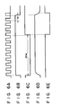
- Multivibrator 51 outputs a single pulse (positive pulse) with a pulse width tw from the output terminal Q when the level at its input terminal B changes to "1" from a "0" level
- multivibrator 52 outputs a single pulse (negative pulse) with a pulse width 8tw from the inverted output terminal Q when the level at its input terminal B changes to "1" from a "0" level.
- data area detector 41 detects the head of ID section 14a or 14b based on a readout signal (binary data). According to this embodiment, to prevent erroneous detection of the ID section due to reading a signal generated by dust or the like, the detected area is not considered to be holding data therein unless more than one byte of sequential data is output therefrom.
- the Q output of multivibrator 51 is set at a "1" level (see Fig. 6B) to be in synchronous with the rising of the first pulse. So as to be in synchronism with the rising of the Q output of multivibrator 51, the inverted Q output of multivibrator 52 shifts to a "0" level as shown in Fig. 6C.
- multivibrator 51 When multivibrator 51 receives more than one byte (8 bits) of input data in succession, it remains in a triggered state so that the Q output remains at a "1" level. However, the inverted Q output of multivibrator 52 returns to a "1" level from a "0" level after time 8tw has elapsed, as shown in Fig. 6C.
- multivibrator 51 When no more binary data is received, multivibrator 51 has its Q output changed to "0" level from “1" level at time tw after the rising of the last pulse, as shown in Fig. 6A. As shown in Fig. 6D, the output of the integration circuit becomes "0" level with a slight delay from the occurrence of the above event, so that the output of NAND gate 53 becomes “1" level as shown in Fig. 6E, thus stopping the generation of the data-area detection signal.
- the Q output of multivibrator 52 is not changed to "1" level from “0" level unless more than one byte of continuous binary data appears. Without detection of more than one byte of continuous binary data, therefore, the data area is not detected, thus preventing erroneous detection of the data area even if binary data is singly outputted due to detection of dust or the like.
- the positional relationship of the data area of an optical card with respect to the optical head can be detected and the data-readout address in ROM 25a, which controls motor speed 26 can be compensated according to the detected relationship. Even if the position of the optical card loaded in the shuttle is deviated or the data area of the card is shifted during manufacturing, therefore, data can be recorded/reproduced accurately and at a high speed.
- the data area may be detected by recording a pattern different from an address in advance in ID sections 14a and 14b and detecting the pattern.
- the data stored in the preset memory should represent the recording position of the pattern.
- the amount of rotation of the motor may be detected by a linear encoder instead of the rotary encoder.
- the ID sections need not be provided at both end portions of an optical card, and the optical head may be moved instead of the shuttle along the tracks on the optical card.
Landscapes
- Engineering & Computer Science (AREA)
- Artificial Intelligence (AREA)
- Computer Vision & Pattern Recognition (AREA)
- Physics & Mathematics (AREA)
- General Physics & Mathematics (AREA)
- Theoretical Computer Science (AREA)
- Optical Recording Or Reproduction (AREA)
- Signal Processing For Digital Recording And Reproducing (AREA)
- Credit Cards Or The Like (AREA)
- Moving Of The Head For Recording And Reproducing By Optical Means (AREA)
Claims (11)
- Appareil d'enregistrement/de reproduction de cartes optiques, comportant :[a] un moyen de support de la carte (24) pour tenir une carte optique (11) qui comprend une zone de données (14a, 15, 14b) dans la partie centrale de la surface de la carte ;[b] une tête optique (21) pour irradier un rayon lumineux sur ladite surface de ladite carte optique (11) ;[c] un moyen de déplacement (26) pour réaliser un mouvement relatif entre ledit support de carte (24) et ladite tête optique (21) de manière à balayer ladite zone de données (14a, 15, 14b) avec ledit rayon lumineux ; et[d] un premier moyen de détection (41) pour détecter la présence de ladite zone de données (14a, 15, 14b) ;
Caractérisé par[e] un second moyen de détection (27, 25e) pour détecter une position relative dudit support de carte (24) par rapport à ladite tête optique (21) ;[f] un moyen (42) pour pré-régler ledit second moyen de détection (27, 25e) de manière ce qu'il émette une donnée de position prédéterminée à l'apparition de ladite zone de données (14a, 15, 14b) ; et[g] un moyen de commande (25, 28) qui, basé sur un signal de sortie dudit second moyen de détection (27, 25e), commande ledit moyen de déplacement (26) de manière à ce que la vitesse relative entre ledit support de carte (24) et ladite tête optique (21) est constante au moins dans la partie de ladite zone de données (14a, 15, 14b). - Appareil selon la revendication 1, caractérisé en ce que ledit premier moyen de détection (41) détecte la présence de ladite zone de données (14a, 15, 14b) par une donnée de sortie binaire reproduite de ladite tête optique (21).
- Appareil selon les revendications 1 ou 2, caractérisé en ce que ledit premier moyen de détection (41) détecte l'apparition de ladite zone de données (14a, 15, 14b) en détectant une configuration de données enregistrée dans ladite zone de données (14a, 15, 14b).
- Appareil selon l'une des revendications 1 à 3, caractérisé en ce que ledit second moyen de détection comprend un codeur (27) qui génère des impulsions qui sont indicatives d'une opération de mouvement respective dudit moyen de déplacement (26) et d'un compteur préréglable (25e) pour compter lesdites impulsions.
- Appareil selon la revendication 4, caractérisé en ce que ledit moyen de commande (25, 28) pré-établit une valeur de compte dudit compteur (25e) basée sur un signal de sortie dudit premier moyen de détection (41).
- Appareil selon les revendications 4 ou 5, caractérisé par une mémoire (25a) pour stocker des données de vitesse correspondant aux positions individuelles relatives dudit moyen de support de carte (24) par rapport à ladite tête optique (21), dans lequel une adresse de lecture est déterminée par le comptage dudit compteur (25e) et dans lequel ledit moyen de déplacement (26) est entraîné à la vitesse correspondant aux données de sortie de ladite mémoire (25a).
- Appareil selon l'une des revendications 4 à 6, caractérisé en ce que la valeur de compte dudit compteur (25e) est soit augmentée, soit diminuée, selon la direction du mouvement relatif.
- Appareil selon l'une des revendications 4 à 7, caractérisé en ce que la valeur de compte dudit compteur (25e) peut être réglée à l'avance par les données qui représentent la position de ladite zone de données (14a, 15, 14b).
- Appareil selon l'une des revendications 1 à 8, caractérisé en ce que ladite zone de données (14a, 15, 14b) comporte un nombre de pistes parallèle (12) s'étendant dans la direction du mouvement relatif.
- Appareil selon l'une des revendications 1 à 9, caractérisé en ce que ladite zone de bord de ladite zone de données (14a, 15, 14b) comporte une section d'identification (14a, 14b).
- Appareil selon l'une des revendications 1 à 10, caractérisé en ce que ladite tête optique (21) génère un rayon laser.
Applications Claiming Priority (2)
| Application Number | Priority Date | Filing Date | Title |
|---|---|---|---|
| JP192411/87 | 1987-07-31 | ||
| JP62192411A JP2549664B2 (ja) | 1987-07-31 | 1987-07-31 | 光カ−ド装置 |
Publications (3)
| Publication Number | Publication Date |
|---|---|
| EP0301537A2 EP0301537A2 (fr) | 1989-02-01 |
| EP0301537A3 EP0301537A3 (en) | 1989-09-13 |
| EP0301537B1 true EP0301537B1 (fr) | 1993-09-29 |
Family
ID=16290869
Family Applications (1)
| Application Number | Title | Priority Date | Filing Date |
|---|---|---|---|
| EP88112227A Expired - Lifetime EP0301537B1 (fr) | 1987-07-31 | 1988-07-28 | Appareil d'enregistrement/reproduction à carte optique |
Country Status (4)
| Country | Link |
|---|---|
| US (1) | US4950876A (fr) |
| EP (1) | EP0301537B1 (fr) |
| JP (1) | JP2549664B2 (fr) |
| DE (1) | DE3884509T2 (fr) |
Families Citing this family (14)
| Publication number | Priority date | Publication date | Assignee | Title |
|---|---|---|---|---|
| JP2545453B2 (ja) * | 1988-11-29 | 1996-10-16 | キヤノン株式会社 | 光学的情報記録再生装置 |
| DE68929242D1 (de) * | 1988-09-30 | 2000-09-21 | Canon Kk | Informationsverarbeitungsgerät, die relative Kopfträgerlage vorstellen mit die relative Kopf/Mediumposition wiedergebenden Signalausgabemitteln |
| US5350910A (en) * | 1988-09-30 | 1994-09-27 | Canon Kabushiki Kaisha | Optical card processing apparatus with means for determining a relative position between head and card |
| JP2723646B2 (ja) * | 1990-03-27 | 1998-03-09 | キヤノン株式会社 | 光学的情報処理装置 |
| US5315572A (en) * | 1991-01-23 | 1994-05-24 | Olympus Optical Co., Ltd. | Information reproducing apparatus capable of eliminating jitters |
| JP2888495B2 (ja) * | 1991-01-29 | 1999-05-10 | オリンパス光学工業株式会社 | 光カード装置 |
| EP0498657A3 (en) * | 1991-02-08 | 1993-03-03 | Canon Kabushiki Kaisha | Optical recording medium, method of reproducing recorded data of optical recording medium, and system for reproducing recorded data of optical recording medium |
| US5105072A (en) * | 1991-03-06 | 1992-04-14 | Olympus Optical Co., Ltd. | Optical information recording/reproducing apparatus having stopping position deviation and correction circuitry relative to movement in the track direction |
| US5265145A (en) * | 1991-03-28 | 1993-11-23 | Lim Boon C | Alphanumeric caller identification telephone |
| JP2977944B2 (ja) * | 1991-05-10 | 1999-11-15 | オリンパス光学工業株式会社 | 光カード装置 |
| US5337304A (en) * | 1991-06-17 | 1994-08-09 | Olympus Optical Co., Ltd. | Optical information recording/reproducing apparatus |
| JPH06333234A (ja) * | 1993-05-19 | 1994-12-02 | Olympus Optical Co Ltd | 光カード記録再生装置 |
| JPH07201144A (ja) * | 1993-12-28 | 1995-08-04 | Nippon Conlux Co Ltd | 情報記録再生装置 |
| CN114690394B (zh) * | 2022-03-31 | 2024-02-09 | 北京空间机电研究所 | 一种空间长寿命高精度旋转望远扫描机构 |
Family Cites Families (20)
| Publication number | Priority date | Publication date | Assignee | Title |
|---|---|---|---|---|
| US3706860A (en) * | 1970-08-20 | 1972-12-19 | Wiltek Inc | Magnetic card data recorder/reproducer |
| US3836753A (en) * | 1971-12-05 | 1974-09-17 | Amp Inc | Magnetic card reader |
| US3852573A (en) * | 1973-11-16 | 1974-12-03 | Scanner | Alignment correction for read scan raster fields |
| US3921969A (en) * | 1974-06-24 | 1975-11-25 | Docutel Corp | Lead screw document transport |
| US3946205A (en) * | 1974-07-22 | 1976-03-23 | Datatype Corporation | Document feed for optical scanner |
| US4544835A (en) * | 1983-12-29 | 1985-10-01 | Drexler Technology Corporation | Data system containing a high capacity optical contrast laser recordable wallet-size plastic card |
| FR2504713B1 (fr) * | 1981-04-27 | 1986-04-11 | Thomson Csf | Disque support d'information a codage angulaire et systeme d'entrainement en rotation d'un tel disque |
| JPS58195982A (ja) * | 1982-05-12 | 1983-11-15 | Hitachi Ltd | マ−ク読取り方式 |
| US4796242A (en) * | 1983-10-12 | 1989-01-03 | Drexler Technology Corporation | Scanning optical card reader |
| US4598393A (en) * | 1984-04-06 | 1986-07-01 | Drexler Technology Corporation | Three-beam optical servo tracking system with two-track parallel readout |
| JPS6151627A (ja) * | 1984-08-22 | 1986-03-14 | Comput Services Corp | 光メモリカ−ド読出し装置 |
| DE3546320A1 (de) * | 1984-12-31 | 1986-07-03 | Canon K.K., Tokio/Tokyo | Geraet zur aufzeichnung und wiedergabe einer optischen information |
| JP2556465B2 (ja) * | 1985-04-05 | 1996-11-20 | キヤノン株式会社 | 記録再生装置の光ヘッドアクセス方法 |
| US4855981A (en) * | 1985-04-18 | 1989-08-08 | Computer Services Corporation | Method and device for reading out optically recorded data and compensating for a drastic change in the position of a line to be read |
| JP2542359B2 (ja) * | 1985-05-22 | 1996-10-09 | キヤノン株式会社 | 情報記録再生装置 |
| JPS61280073A (ja) * | 1985-06-06 | 1986-12-10 | Canon Inc | 情報記録再生装置 |
| JPH0636266B2 (ja) * | 1985-10-18 | 1994-05-11 | キヤノン株式会社 | 情報記録再生装置 |
| JPS634428A (ja) * | 1986-06-25 | 1988-01-09 | Sony Corp | 光カ−ド記録・再生装置 |
| JP2642621B2 (ja) * | 1986-07-31 | 1997-08-20 | オリンパス光学工業株式会社 | 光カード |
| JPS6370986A (ja) * | 1986-09-12 | 1988-03-31 | Pioneer Electronic Corp | 記録デイスクの複合索引コ−ド読取り記憶方式 |
-
1987
- 1987-07-31 JP JP62192411A patent/JP2549664B2/ja not_active Expired - Lifetime
-
1988
- 1988-07-25 US US07/224,051 patent/US4950876A/en not_active Expired - Fee Related
- 1988-07-28 DE DE88112227T patent/DE3884509T2/de not_active Expired - Fee Related
- 1988-07-28 EP EP88112227A patent/EP0301537B1/fr not_active Expired - Lifetime
Also Published As
| Publication number | Publication date |
|---|---|
| US4950876A (en) | 1990-08-21 |
| DE3884509T2 (de) | 1994-02-10 |
| EP0301537A2 (fr) | 1989-02-01 |
| JP2549664B2 (ja) | 1996-10-30 |
| EP0301537A3 (en) | 1989-09-13 |
| JPS6437761A (en) | 1989-02-08 |
| DE3884509D1 (de) | 1993-11-04 |
Similar Documents
| Publication | Publication Date | Title |
|---|---|---|
| US4950876A (en) | Optical card recording/reproducing apparatus with compensation for displacement deviation between data area of optical card and laser beam | |
| US4527263A (en) | Eccentricity correction for an optical disk device | |
| JPH08167153A (ja) | 光ディスク装置 | |
| EP0366439A2 (fr) | Appareil à disque magnétique | |
| EP0089020A2 (fr) | Appareil de traitement de données comportant des moyens d'enregistrement de données par déplacement d'une tête vers une pluralité de pistes | |
| EP0678861B1 (fr) | Appareil et méthode d'enregistrement et/ou de reproduction optique d'information à actionneur à onde vibratoire ou dispositif à moteur actionné par vibration | |
| CA1196099A (fr) | Dispositif pour mettre rapidement la tete d'un lecteur optique a la position desiree sur un disque d'enregistrement | |
| EP0078060B1 (fr) | Procédé et appareil pour retrouver des informations dans une piste sélectionnée d'un disque d'enregistrement | |
| US4719611A (en) | Apparatus for controlling a recording operation of an optical information recording apparatus | |
| EP0404942B1 (fr) | Disque optique et commande du mouvement de son spot optique | |
| US5105072A (en) | Optical information recording/reproducing apparatus having stopping position deviation and correction circuitry relative to movement in the track direction | |
| US6407877B1 (en) | Recording/reproducing method and apparatus in which head driver is unlocked when medium is loaded and when track position information formulation based on optical signal input has been completed | |
| EP0657877A1 (fr) | Procédé et dispositif pour la recherche de piste pour l'utilisation avec un appareil d'enregistrement et de reproduction optique d'information | |
| US5248888A (en) | Process for positioning a record changing device having reflective markers | |
| US5451762A (en) | Optical card having guide patterns for information line positioning and optical card recording/reproducing apparatus | |
| US5144610A (en) | Method of recording data on optical card by performing blank checking without scanning an entire track | |
| EP0167177A1 (fr) | Procédé pour retrouver des informations dans une piste sélectionnée d'un disque d'enregistrement | |
| JP2667479B2 (ja) | 光カード装置 | |
| EP0263685A2 (fr) | Appareil de positionnement de champ magnétique supplémentaire | |
| JP2724002B2 (ja) | 光カード装置 | |
| EP0327108B1 (fr) | Système de commande d'accès à un transducteur | |
| US5268891A (en) | Optical recording/reproducing apparatus which reduces seek time by timing initiation of tracking control based upon characteristics of record medium vibrations relative to an optical pick-up head | |
| US5373404A (en) | Helical scan type rotary head drum unit | |
| WO1998041832A2 (fr) | Codeur de position de tete de lecteur de disque | |
| KR100200584B1 (ko) | 컴팩트 디스크 드라이브의 슬래드 모터 제동 방법 |
Legal Events
| Date | Code | Title | Description |
|---|---|---|---|
| PUAI | Public reference made under article 153(3) epc to a published international application that has entered the european phase |
Free format text: ORIGINAL CODE: 0009012 |
|
| 17P | Request for examination filed |
Effective date: 19880728 |
|
| AK | Designated contracting states |
Kind code of ref document: A2 Designated state(s): DE GB IT |
|
| PUAL | Search report despatched |
Free format text: ORIGINAL CODE: 0009013 |
|
| AK | Designated contracting states |
Kind code of ref document: A3 Designated state(s): DE GB IT |
|
| 17Q | First examination report despatched |
Effective date: 19911206 |
|
| GRAA | (expected) grant |
Free format text: ORIGINAL CODE: 0009210 |
|
| AK | Designated contracting states |
Kind code of ref document: B1 Designated state(s): DE GB IT |
|
| REF | Corresponds to: |
Ref document number: 3884509 Country of ref document: DE Date of ref document: 19931104 |
|
| ITF | It: translation for a ep patent filed | ||
| PLBE | No opposition filed within time limit |
Free format text: ORIGINAL CODE: 0009261 |
|
| STAA | Information on the status of an ep patent application or granted ep patent |
Free format text: STATUS: NO OPPOSITION FILED WITHIN TIME LIMIT |
|
| 26N | No opposition filed | ||
| PGFP | Annual fee paid to national office [announced via postgrant information from national office to epo] |
Ref country code: GB Payment date: 20000726 Year of fee payment: 13 |
|
| PGFP | Annual fee paid to national office [announced via postgrant information from national office to epo] |
Ref country code: DE Payment date: 20000727 Year of fee payment: 13 |
|
| PG25 | Lapsed in a contracting state [announced via postgrant information from national office to epo] |
Ref country code: GB Free format text: LAPSE BECAUSE OF NON-PAYMENT OF DUE FEES Effective date: 20010728 |
|
| GBPC | Gb: european patent ceased through non-payment of renewal fee |
Effective date: 20010728 |
|
| PG25 | Lapsed in a contracting state [announced via postgrant information from national office to epo] |
Ref country code: DE Free format text: LAPSE BECAUSE OF NON-PAYMENT OF DUE FEES Effective date: 20020501 |
|
| PG25 | Lapsed in a contracting state [announced via postgrant information from national office to epo] |
Ref country code: IT Free format text: LAPSE BECAUSE OF NON-PAYMENT OF DUE FEES Effective date: 20050728 |