EP0302151A1 - Méthode pour commander le profil d'une bande dans un laminoir planétaire - Google Patents
Méthode pour commander le profil d'une bande dans un laminoir planétaire Download PDFInfo
- Publication number
- EP0302151A1 EP0302151A1 EP87306932A EP87306932A EP0302151A1 EP 0302151 A1 EP0302151 A1 EP 0302151A1 EP 87306932 A EP87306932 A EP 87306932A EP 87306932 A EP87306932 A EP 87306932A EP 0302151 A1 EP0302151 A1 EP 0302151A1
- Authority
- EP
- European Patent Office
- Prior art keywords
- crown
- planetary
- rolls
- feeding
- feeding rolls
- Prior art date
- Legal status (The legal status is an assumption and is not a legal conclusion. Google has not performed a legal analysis and makes no representation as to the accuracy of the status listed.)
- Withdrawn
Links
Images


Classifications
-
- B—PERFORMING OPERATIONS; TRANSPORTING
- B21—MECHANICAL METAL-WORKING WITHOUT ESSENTIALLY REMOVING MATERIAL; PUNCHING METAL
- B21B—ROLLING OF METAL
- B21B1/00—Metal-rolling methods or mills for making semi-finished products of solid or profiled cross-section; Sequence of operations in milling trains; Layout of rolling-mill plant, e.g. grouping of stands; Succession of passes or of sectional pass alternations
- B21B1/22—Metal-rolling methods or mills for making semi-finished products of solid or profiled cross-section; Sequence of operations in milling trains; Layout of rolling-mill plant, e.g. grouping of stands; Succession of passes or of sectional pass alternations for rolling plates, strips, bands or sheets of indefinite length
- B21B1/224—Edge rolling of flat products
-
- B—PERFORMING OPERATIONS; TRANSPORTING
- B21—MECHANICAL METAL-WORKING WITHOUT ESSENTIALLY REMOVING MATERIAL; PUNCHING METAL
- B21B—ROLLING OF METAL
- B21B13/00—Metal-rolling stands, i.e. an assembly composed of a stand frame, rolls, and accessories
- B21B13/18—Metal-rolling stands, i.e. an assembly composed of a stand frame, rolls, and accessories for step-by-step or planetary rolling; pendulum mills
- B21B13/20—Metal-rolling stands, i.e. an assembly composed of a stand frame, rolls, and accessories for step-by-step or planetary rolling; pendulum mills for planetary rolling
-
- B—PERFORMING OPERATIONS; TRANSPORTING
- B21—MECHANICAL METAL-WORKING WITHOUT ESSENTIALLY REMOVING MATERIAL; PUNCHING METAL
- B21B—ROLLING OF METAL
- B21B27/00—Rolls, roll alloys or roll fabrication; Lubricating, cooling or heating rolls while in use
- B21B27/02—Shape or construction of rolls
- B21B27/021—Rolls for sheets or strips
- B21B2027/022—Rolls having tapered ends
-
- B—PERFORMING OPERATIONS; TRANSPORTING
- B21—MECHANICAL METAL-WORKING WITHOUT ESSENTIALLY REMOVING MATERIAL; PUNCHING METAL
- B21B—ROLLING OF METAL
- B21B39/00—Arrangements for moving, supporting, or positioning work, or controlling its movement, combined with or arranged in, or specially adapted for use in connection with, metal-rolling mills
- B21B39/02—Feeding or supporting work; Braking or tensioning arrangements, e.g. threading arrangements
- B21B39/10—Arrangement or installation of feeding rollers in rolling stands
Definitions
- the present invention relates to a method of controlling strip crown in planetary rolling of metallic material on a planetary mill for improving strip crown of planetary-rolled strips by preventing from occurring edge-drop and high spot of the strip crown.
- a rolling mill such as a tandem mill, a steckel mill, a planetary mill or the like.
- the hot strip manufactured by such a rolling mill always has a thickness deviation along the width of the strip which is referred to a strip crown.
- the strip crown is classified into a center crown occurred by gently increasing the thickness in the central region of the strip and an edge drop occurred by sharply decreasing the thickness in the edge region of the strip.
- some methods such as a method using roll benders for work rolls and backup rolls in finishing roll stands, a method using a six roll mill referred to a HC mill and a method using tapered rolls.
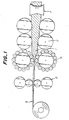
- the planetary mill comprises a pair of backup rolls having a large diameter and a plurality of planetary rolls having a small diameter arrenged around each of the backup rolls.
- a slab is rolled by one to three sets of feeding rolls and then rolled by the planetary rolls.
- the slab is subjected to small reduction several ten times by the planetary rolls and resulted in a large total reduction more than 90 % by the planetary mill. Therefore, the planetary mill has the function of the latter half of roughing roll stands and the finishing roll stands of the tandem mill.
- the planetary mill is subjected to a very small roll separating force in spite of a large total reduction and the center crown of the planetary-rolled strip is very small owing to the backup rolls of the large diameter and the total crown depends on the edge drop.
- the conventional feeding rolls used on the planetary mill line has a straight crown (Fig. 6) or a curved crown defined by a quadratic curve for correction of elastic deformation of the rolls or convex crown defined by a sine curve (Fig. 7).
- the thickness of the rolled strip having for example five feet width sometimes locally increases at a region width 50 ⁇ 150 mm from the edge of the strip. It is called high spot.
- This phenomenon is also occurred when a slab having a flat crown after feeding rolls is fed to the planetary rolls.
- the cause of such a phenomenon has not been made entirely clear. It is conjected that the phenomenon is caused by bending of comparatively slender planetary rolls, but the cause is still unclear and the measures have not been entireby taken.
- planetary rolling when the thickness of the center of the rolled strip is increased, the rolled strip shows center buckling. And when the thickness of the rolled strip is locally increased, the rolled strip tends to show quater buckling.
- the conventional method of rolling on the planetary mill line has a problem such that the edge drop of the strip crown could not be decreased and the local increase of the thickness, i.e. high spot, could not be prevented.
- the object of the present invention is to decrease the edge drop and to prevent the local increase of the thickness of planetary-rolled strip.
- the present invention provide a method of controlling strip crown in planetary rolling on a planetary mill line comprising edger rolls, feeding rolls, planetary rolls and planishing rolls, which method is characterized in that the feeding roll neighbering to the planetary rolls has a roll crown such that the central region is flat or slightly curved for correcting a bend of the feeding roll and has a diameter at each side portion spaced from each of both side ends of the effective rolling width of the feeding rolls by a distance determined a roll gap between the central regions of a pair of feeding rolls is larger than a diameter at the central region of the feeding rolls by 0.1 ⁇ 1 % and further the side region between the side portion having the increased diameter and the side end of the effective rolling width is tapered to provide smaller diameter at the side end than the diameter of the central reagion, thereby to provide a planetary-rolled strip having a substantially flat strip crown.
- the inventors made tests and studied the behavior of rolling in the planetary mill and found that the strip crown of planetary rolled strip is largely depended on the three dimentional deformation of the slab and is substantially determined by combination of the distributin of spreading in the direction of width of the slab and the distribution of elongation in the longitudinal direction of the slab. It is also found from the result of the test that in rolling on the conventional planetary mill line according to the prior art, the edge drop in problem occurs at a portion of insufficient volume of the slab material in edge region and also the localy increasing of thickness in problem occurs at a portion of excessive volume of the slab material.
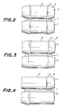
- the feeding rolls 2 has a roll crown such that the central region 3 is flat or is slightly curved for correcting a bend of the feeding roll and a diameter at side portion 4 spaced from the side end of the effective rolling width of the feeding roll by a distance determined by a roll gap between the central regions 3.3 of a pair of feeding rolls 2.2 is larger than a diameter of the central reagion of the feeding rolls by 0.1 ⁇ 1 % of the diameter thereof to form an enlarged portion 4.
- the side region 5 between the side enlarged portion 4 and the side end is tapered by a taper angle from the enlarged portion 4 towards the side end.
- the strip crown can be made flat by planetary rolling after feeding rolls.
- the diameter of the side enlarged portion 4 and the taper angle of the taperted side reagion 5 are critical in order to obtain a satisfactry flatness of the strip crown. Since the rolling condition is usualy standerdized, it is easy to select the correct diameter of the enlarged side portion 4 and the taper angle of the tapered side region 5.
- the feeding roll is formed with the enlarged side portion 4 at a position spaced from the side end of the effective rolling width by a distance of 100 mm and is tapered from the enlarged side portion 4 towards the side end.
- the thickness of the slab to be planetary rolled is 55 mm, it is most preferable that the diameter of the feeding roll is decreased from a position spaced from the side end of the effective rolling width by a distance of 80 mm.
- FIG. 3 shows another embodiment of a pair of the feeding rolls 2 only one of which has the enlarged side portion 4 at the position spaced from the side end and the tapered side reagion 5 and the other feeding roll 2 has not the enlarged side portion, but this embodiment can carry out the similar effect.
- Fig. 4 also shows another embodiment of a pair of the feeding rolls 2 having the enlarged side portion 4 and the tapered side reagion 5 at only one side thereof, but this embodiment can also carry the similar effect.
- Fig. 8 shows the crown profile of slabs having a width of 1050 mm after feeding rolls according to the method of the present invention and the conventional rolling method.
- Figs. 8a and 8b show the slab profiles after feeding rolls according to the conventional method.
- Fig. 8a shows the crown profile of the slab rolled by the feeding rolls having the straight crown as shown in Fig. 6.
- Fig. 8b shows the crown profile of the slab rolled by the feeding rolls having the curved crown defined by the quadratic curve or convex crown defined by a sine curve as shown in fig. 7 and the slab has thickness of 83 mm at the width center and thickness of 85 mm at the side end portions of the effective rolling width.
- Figs. 8c, 8d, 8e, 8f show the slab profiles according to the method of the present invention.
- Fig. 8c shows the crown profile of the slab rolled by the feeding rolls having the roll crown profile shown in fig. 2 and the slab has thickness of 83 mm at the width center, thickness of 78 mm at the thin portion formed by the enlarged side portions of the upper and the lower feeding rolls and thickness of 85 mm at the side ends of the effective rolling width.
- the postion of the thin portion in the width direction of the thicker slab is nearer to the width center than the thiner slab.
- Fig. 8d shows the crown profile of the slab rolled by the feeding rolls having the roll crown profile shown in fig.
- Fig. 8e shows the crown profile of the slab rolled by the feeding rolls having the roll crown profile shown in Fig. 5, one of which feeding rolls has the roll crown as the same as that of Fig. 2 and the other has the straiight crown and the slab has thickness of 83 mm at the width center, thickness of 78 mm at the thin positions and thickness of 85 mm at the side ends of the effective rolling width.
- Fig. 8f shows the crown profile of the slab rolled by the feeding rolls having the roll crown profile shown in Fig. 4 and the slab has thickness of 83 mm at the width center, thickness of 78 mm at the thin portions and thickness of 85 mm at the side ends of the effective rolling width of the tapered side reagion.
- Fig. 9 shows relations between distance from the center of strip and the thickness deviation of the strip crown of planetary-rolled strips of the slabs shown in Figs. 8a, 8b, 8c, 8d, 8e, and 8f. It is seen from Fig. 9 that the planetary-rolled strips according to the conventional method using the slabs having the straight crown and the sine courved crown shown in figs. 8a, and 8b have large edge drops and locally increased thickness as shown in Fig. 9 (a), (b). On the contrary, the planetary-rolled strips according to the present invention using the feeding rolled slabs having crown profile shown in fig. 8c, 8d, 8e, and 8f have small edge drap and flat crown shape without increased thickness as shown in Fig. 9 (c), (d), (e), and (f).
- the present invention is also able to apply for not only sendzimir type planetary mill, but also Krupp-Platzer type planetary mill having double groups of planetary rolls.
- the present invention is also able to apply for Roll Cast type planetary mill, double three high mills, pendulum mills, DSW mills and others of same rolling mechanism as that of the planetary mill.
- the present invention is enable to obtain planetary-rolled strip having flat profile with limited edge drop and local thickness variation and to provide high grade strips usable for cold rolling material as well as hot rolled products.
- the present invention is also carried out by preparing the feeding rolls having the desired crown profile shaped by machining with low investment. Accordingly the present invention is capable to bring a large economical effect.
Landscapes
- Engineering & Computer Science (AREA)
- Mechanical Engineering (AREA)
- Metal Rolling (AREA)
- Reduction Rolling/Reduction Stand/Operation Of Reduction Machine (AREA)
Applications Claiming Priority (1)
| Application Number | Priority Date | Filing Date | Title |
|---|---|---|---|
| JP61016724A JPH0613123B2 (ja) | 1986-01-30 | 1986-01-30 | プラネタリ−ミルライン圧延方法 |
Publications (1)
| Publication Number | Publication Date |
|---|---|
| EP0302151A1 true EP0302151A1 (fr) | 1989-02-08 |
Family
ID=11924208
Family Applications (1)
| Application Number | Title | Priority Date | Filing Date |
|---|---|---|---|
| EP87306932A Withdrawn EP0302151A1 (fr) | 1986-01-30 | 1987-08-05 | Méthode pour commander le profil d'une bande dans un laminoir planétaire |
Country Status (3)
| Country | Link |
|---|---|
| US (1) | US4856313A (fr) |
| EP (1) | EP0302151A1 (fr) |
| JP (1) | JPH0613123B2 (fr) |
Families Citing this family (7)
| Publication number | Priority date | Publication date | Assignee | Title |
|---|---|---|---|---|
| JPH0613123B2 (ja) * | 1986-01-30 | 1994-02-23 | 日本冶金工業株式会社 | プラネタリ−ミルライン圧延方法 |
| GB2222376B (en) * | 1988-08-29 | 1993-04-07 | Sendzimir Inc T | Apparatus and method for cold rolling of metal strip |
| JPH07104636B2 (ja) * | 1989-04-03 | 1995-11-13 | キヤノン株式会社 | 定着装置 |
| US5728252A (en) * | 1995-09-19 | 1998-03-17 | Polaroid Corporation | Method and apparatus for laminating image-bearing media |
| US6086242A (en) * | 1998-02-27 | 2000-07-11 | University Of Utah | Dual drive planetary mill |
| DE102007047875A1 (de) * | 2007-11-28 | 2009-06-04 | Hilti Aktiengesellschaft | Profil |
| DE102011079095A1 (de) * | 2011-07-13 | 2013-01-17 | Hilti Aktiengesellschaft | Verfahren zum Herstellen eines Profils aus einem Blechband |
Citations (4)
| Publication number | Priority date | Publication date | Assignee | Title |
|---|---|---|---|---|
| JPS5166263A (ja) * | 1974-12-06 | 1976-06-08 | Hitachi Ltd | Kuraunseigyokanonajuseiatsuenki |
| JPS56165503A (en) * | 1980-05-26 | 1981-12-19 | Kawasaki Steel Corp | Rolling method with controlled draft percentage |
| JPS59193705A (ja) * | 1983-04-18 | 1984-11-02 | Nippon Yakin Kogyo Co Ltd | プラネタリ−ミルラインによる熱間圧延方法 |
| JPS62176603A (ja) * | 1986-01-30 | 1987-08-03 | Nippon Yakin Kogyo Co Ltd | プラネタリ−ミルライン圧延方法 |
Family Cites Families (5)
| Publication number | Priority date | Publication date | Assignee | Title |
|---|---|---|---|---|
| US3492849A (en) * | 1966-08-22 | 1970-02-03 | Rotary Profile Anstalt | Rolling of metal billets |
| US3789646A (en) * | 1972-10-05 | 1974-02-05 | Sendzimir Inc T | Planetary mill for producing scallop-free strip |
| JPS56117823A (en) * | 1980-02-16 | 1981-09-16 | Sumitomo Metal Ind Ltd | Bridle roll for skin pass mill |
| GB8414600D0 (en) * | 1984-06-08 | 1984-07-11 | Davy Mckee Sheffield | Rolling metal slab |
| US4730475A (en) * | 1986-05-06 | 1988-03-15 | International Rolling Mills Consultants, Inc. | Rolling mill method |
-
1986
- 1986-01-30 JP JP61016724A patent/JPH0613123B2/ja not_active Expired - Lifetime
-
1987
- 1987-08-05 EP EP87306932A patent/EP0302151A1/fr not_active Withdrawn
- 1987-09-16 US US07/097,199 patent/US4856313A/en not_active Expired - Fee Related
Patent Citations (4)
| Publication number | Priority date | Publication date | Assignee | Title |
|---|---|---|---|---|
| JPS5166263A (ja) * | 1974-12-06 | 1976-06-08 | Hitachi Ltd | Kuraunseigyokanonajuseiatsuenki |
| JPS56165503A (en) * | 1980-05-26 | 1981-12-19 | Kawasaki Steel Corp | Rolling method with controlled draft percentage |
| JPS59193705A (ja) * | 1983-04-18 | 1984-11-02 | Nippon Yakin Kogyo Co Ltd | プラネタリ−ミルラインによる熱間圧延方法 |
| JPS62176603A (ja) * | 1986-01-30 | 1987-08-03 | Nippon Yakin Kogyo Co Ltd | プラネタリ−ミルライン圧延方法 |
Non-Patent Citations (4)
| Title |
|---|
| CAHIERS D'INFORMATIONS TECHNIQUES DE LA REVUE DE MATALLURGIE, vol. 83, no. 12, December 1986, pages 867-874, Paris, FR; A. QUEHEN et al.: "Présentation du Rollcast, laminoir planétaire de produits plats" * |
| PATENT ABSTRACTS OF JAPAN, vol. 6, no. 50 (M-120)[928], 3rd April 1982; & JP-A-56 165 503 (KAWASAKI SEITETSU K.K.) 19-12-1981 * |
| PATENT ABSTRACTS OF JAPAN, vol. 9, no. 57 (M-363)[1780], 13th March 1985; & JP-A-59 193 705 (NIHON YAKIN KOGYO K.K.) 02-11-1984 * |
| TRANSACTIONS OF NATIONAL RESEARCH INSTITUTE FOR METALS, vol. 26, no. 4, 1984, pages 279-286; T. DENDO et al.: "Shape and quality of strips rolled by planetary mill", & JOURNAL OF THE JAPANESE SOCIETY OF THE TECHNOLOGY OF PLASTICITY, vol. 22, no. 247, 1981, pages 839-846 (Cat. D) * |
Also Published As
| Publication number | Publication date |
|---|---|
| JPH0613123B2 (ja) | 1994-02-23 |
| US4856313A (en) | 1989-08-15 |
| JPS62176603A (ja) | 1987-08-03 |
Similar Documents
| Publication | Publication Date | Title |
|---|---|---|
| US5622073A (en) | Six high rolling mill | |
| EP0302151A1 (fr) | Méthode pour commander le profil d'une bande dans un laminoir planétaire | |
| US5636544A (en) | Cold rolling method for a metal strip and a mill array | |
| EP0543014B1 (fr) | Laminoir a six etages | |
| US5131252A (en) | Apparatus and method for cold rolling of metal strip | |
| JPH0521653B2 (fr) | ||
| JPH08117829A (ja) | 薄鋼板の冷間圧延方法 | |
| CA1302743C (fr) | Methode de controle du bombement de la bande, dans un laminoir planetaire | |
| JP2761796B2 (ja) | 冷間圧延におけるクラウン制御方法 | |
| JPH08267114A (ja) | 冷間圧延におけるエッジドロップ制御圧延方法 | |
| JP2761797B2 (ja) | タンデムミルによる冷間圧延におけるクラウン制御方法 | |
| JP3022222B2 (ja) | 金属板の冷間圧延機 | |
| JP2519103B2 (ja) | 電磁鋼板の冷間圧延方法 | |
| JPH05261416A (ja) | 板プロフィル制御方法 | |
| JPH0618651B2 (ja) | 薄鋼板の長手方向にわたる、幅方向板厚差制御方法と制御装置 | |
| JPH0796123B2 (ja) | クラスター型多段圧延機による圧延時の鋼帯形状不良発生防止方法 | |
| JPH0364201B2 (fr) | ||
| JPH05200404A (ja) | エッジドロップの小さい金属板の製造方法 | |
| JPH0763737B2 (ja) | ワークロールと接する中間ロール及びそれが組み込まれた多段圧延機 | |
| JPH1157827A (ja) | 板材圧延におけるエッジドロップ制御方法 | |
| JPH0532123B2 (fr) | ||
| EP0194322B1 (fr) | Laminoir | |
| JPS60250806A (ja) | 熱間圧延法 | |
| JPH1029010A (ja) | 板材の幅方向板厚制御方法 | |
| JPH0780003B2 (ja) | 幅方向の板厚偏差を制御する板材の製造方法 |
Legal Events
| Date | Code | Title | Description |
|---|---|---|---|
| PUAI | Public reference made under article 153(3) epc to a published international application that has entered the european phase |
Free format text: ORIGINAL CODE: 0009012 |
|
| AK | Designated contracting states |
Kind code of ref document: A1 Designated state(s): DE FR GB |
|
| STAA | Information on the status of an ep patent application or granted ep patent |
Free format text: STATUS: THE APPLICATION IS DEEMED TO BE WITHDRAWN |
|
| 18D | Application deemed to be withdrawn |
Effective date: 19890809 |
|
| RIN1 | Information on inventor provided before grant (corrected) |
Inventor name: OKAMOTO, YOSHIO Inventor name: TAKAHASHI, HIROKI Inventor name: INADA, SOUICHI Inventor name: MIURA, RYOZO |