EP0302405B1 - Giesseinrichtung einer Giesspfanne, die geschmolzenes Metall enthält - Google Patents
Giesseinrichtung einer Giesspfanne, die geschmolzenes Metall enthält Download PDFInfo
- Publication number
- EP0302405B1 EP0302405B1 EP88112308A EP88112308A EP0302405B1 EP 0302405 B1 EP0302405 B1 EP 0302405B1 EP 88112308 A EP88112308 A EP 88112308A EP 88112308 A EP88112308 A EP 88112308A EP 0302405 B1 EP0302405 B1 EP 0302405B1
- Authority
- EP
- European Patent Office
- Prior art keywords
- vessel
- pouring
- opening
- closing
- molten
- Prior art date
- Legal status (The legal status is an assumption and is not a legal conclusion. Google has not performed a legal analysis and makes no representation as to the accuracy of the status listed.)
- Expired - Lifetime
Links
Images


Classifications
-
- B—PERFORMING OPERATIONS; TRANSPORTING
- B22—CASTING; POWDER METALLURGY
- B22D—CASTING OF METALS; CASTING OF OTHER SUBSTANCES BY THE SAME PROCESSES OR DEVICES
- B22D41/00—Casting melt-holding vessels, e.g. ladles, tundishes, cups or the like
- B22D41/08—Casting melt-holding vessels, e.g. ladles, tundishes, cups or the like for bottom pouring
-
- B—PERFORMING OPERATIONS; TRANSPORTING
- B22—CASTING; POWDER METALLURGY
- B22D—CASTING OF METALS; CASTING OF OTHER SUBSTANCES BY THE SAME PROCESSES OR DEVICES
- B22D41/00—Casting melt-holding vessels, e.g. ladles, tundishes, cups or the like
- B22D41/50—Pouring-nozzles
- B22D41/60—Pouring-nozzles with heating or cooling means
-
- C—CHEMISTRY; METALLURGY
- C21—METALLURGY OF IRON
- C21C—PROCESSING OF PIG-IRON, e.g. REFINING, MANUFACTURE OF WROUGHT-IRON OR STEEL; TREATMENT IN MOLTEN STATE OF FERROUS ALLOYS
- C21C5/00—Manufacture of carbon-steel, e.g. plain mild steel, medium carbon steel or cast steel or stainless steel
- C21C5/28—Manufacture of steel in the converter
- C21C5/42—Constructional features of converters
- C21C5/46—Details or accessories
- C21C5/4653—Tapholes; Opening or plugging thereof
Definitions
- This invention relates generally to vessels designed to contain molten metal at high temperatures, such as Bessemer converters, metal mixers, electric furnaces, ladles, and tundishes. More particularly, the invention relates to devices for tapping or pouring out molten metal through the bottoms of such vessels.
- a vessel of the above exemplified kind for containing molten metal (hereinafter referred to as vessel) is used to receive molten metal poured thereinto, to melt or smelt a metal therewithin, or to hold a molten metal therewithin for a specific time for refining or reserving and thereafter to pour out the molten metal for conveyance to a succeeding process.
- a vessel of this character is required to have the functional capability, in addition to that of receiving and retaining molten metal, of appropriately pouring out the molten metal.
- the molten metal handled by these vessels are at high temperatures, ordinary metal valves cannot be used at the pouring out openings at the bottoms of these vessels. For this reason, one of the following principal methods has heretofore been used to tap or pour molten metal out of these vessels.
- a pouring orifice of a special form is formed in the furnace bottom and is provided with a pouring device of such a construction that, by varying the rotational angle and the inclination angle of the furnace, the molten metal within the furnace can be poured out, or its pouring out can be stopped as proposed in Japanese Laid-Open Patent Application No. 234915/1985.
- An important feature of this invention which provides, in a vessel of the instant character, a pouring device having a mechanism for opening/closing the lower end of a pouring orifice formed in the vessel bottom, is the provision of a cooling system for cooling the upper end of the pouring orifice by using a cooling medium, which cooling system can be used for introducing other fluids such as argon gas, nitrogen gas, and oxygen into the vessel for various purposes, as will be described more fully hereinafter.
- This cooling system One important function of this cooling system is to supply the cooling medium through tuyeres into the vessel in order to cool the upper opening of the pouring hole and surrounding parts when a cycle of pouring is nearing its conclusion and the slag floating on the molten steel is approaching the pouring orifice thereby to cause the molten steel or slag to coagulate and form a sealing mass over the upper opening of the pouring orifice, thus stopping the pouring. Then, with vessel in this state the above mentioned opening/closing mechanism is operated to fully close the pouring orifice.
- a pouring device of a molten-metal-containing vessel comprising: a refractory structure of substantially tubular shape which forms a lining fixed to the wall surface of a through hole formed through the bottom of the vessel, and which forms therethrough a pouring orifice having an upper opening to the interior of the vessel and a lower opening to the outside of the vessel, characterized by a cooling device operable to blow a cooling medium to the region of the upper opening and the vicinity thereof for cooling the upper opening and the region in the vicinity thereof, and an opening/closing mechanism installed outside of the vessel for mechanically opening and closing the lower opening thereby to permit pouring out of molten metal contained in the vessel and to stop this pouring out.
- a cooling device is disclosed in JP-A-60 - 234 915.
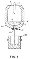
- An example of a Bessemer converter provided with an example of the pouring device according to this invention as illustrated schematically in FIG. 1 comprises essentially a converter vessel 1 for containing molten steel 3 with a layer of slag 4 covering the upper surface of the molten steel 3, an overhead oxygen lance 21 insertable from above into the vessel through the upper furnace opening 1b thereof, and the pouring device 11 provided at the bottom of the vessel 1.
- a ladle 22 is positioned immediately below the pouring device 11 to receive molten steel tapped or poured therefrom and to transport this molten steel to a succeeding process. The pouring operation will be described more fully hereinafter.
- the bottom of the converter vessel 1 comprises a furnace iron cladding 1a and an inner vessel refractory lining 2 comprising permanent bricks 2b in contact with the inner surface of the iron cladding 1a and consumable bricks 2a in contact with the inner surface of the permanent bricks 2b.
- This bottom of the vessel 1 is provided with the pouring device 11 of the invention, which is constructed and installed in the following manner.
- a pouring drain orifice 12 is formed through the center of the bottom of the vessel 1 and is provided around its inner peripheral surface with a cooling device 13 comprising tuyeres 13a opening at their upper ends into the interior of the vessel 1, tuyere pipes 13b connected to the lower ends of the tuyeres 13a, and piping 13c for supplying a cooling medium 19 to the tuyere pipes 13b.
- the tuyeres 13a comprises, for example, a plurality of nozzles formed from a heat-resistant metal material and opening into the interior of the vessel 1 around the inner or upper opening 12a of the pouring drain orifice 12.
- a refractory material 14a for protecting the interior surface
- refractory materials 14b and 14c are provided to fill the spaces between the furnace refractory structure 2 and the tuyeres 13a and the tuyere pipes 13b.
- These refractories are supported by a metal frame 15, which in turn is fixed by way of metal gusset stays 16 to the furnace iron cladding 1a.
- these refractories 14a, 14b and 14c may be considered collectively as constituting a tubular refractory structure containing the cooling device 13 and forming a lining fixed to the wall surface of a through hole formed through the bottom of the vessel.
- the outer or lower opening 12b of the pouring drain orifice 12, and therefore the entire drain orifice 12, can be closed by a nozzle stopper 17 comprising a swingable arm 17b pivotally supported at its proximal end by way of a pivot shaft 17a on a fixed part (not shown) of the converter vessel structure, a nozzle plug 17c made of a refractory material and fixed to the distal end of the arm 17b, and a driving device 18 for driving the arm 17b in closing and opening movements to bring the plug 17c into closed state in and against the rim of the lower opening 12b and into an opened state as shown in FIG. 2.
- the nozzle stopper 17 In the state of the converter 1 shown in FIG. 1, the nozzle stopper 17 is in its opened state, and the molten steel 3 of one heat is being poured through the pouring orifice 12 into the ladle 22 positioned directly below the converter vessel 1. Then, as this pouring continues, the quantity of the molten steel 3 in the vessel 1 becomes small, and the slag 4 is about to be discharged. At this point, immediately before the slag 4 is discharged, the tapping or pouring operation is stopped by the following procedural steps (1) through (4).
- This pouring device 11 An important feature of this pouring device 11 is that, since the flow of the molten steel 3 into the pouring orifice 12 is initially stopped by the closure of the upper opening 12a of the pouring orifice 12 by the cooling and coagulation of the slag 4 (or the molten steel 3) due to the injection of the cooling medium 19, the nozzle plug 17 itself is not required to shut off the outflow of the molten steel 3 or the slag 4 by direct contact. For this reason, damage to the nozzle plug 17c is very rare and slight.
- the ladle 22, into which the molten steel has been poured is transported away to the succeeding process, and the converter 1 is inverted to discharge the slag 4 within the converter 1 through its throat or upper opening 1b. Then the converter 1 is returned to its upright state, and the next batch of molten iron 3b for refining is received in the converter 1.
- the operational steps of refining the molten iron 3b thus received in the converter 1 to the pouring out therefrom are as follows.
- the nozzle stopper 17 When the converter 1 is inverted to discharge the slag remaining therein as described hereinbefore, the nozzle stopper 17 is opened to pack a material such as sand 25 into the pouring hole 12 beforehand, and then, if the nozzle stopper 17 is left closed as indicated in FIG. 5, a coagulated layer 3a will not be able to form deeply into the pouring orifice 12, whereby when the nozzle stopper 17 is thereafter opened, the molten steel 3 can be poured smoothly.
- a material such as sand 25
- a sliding gate 31 is slidably installed at the lower opening 12b of the pouring orifice 12 in place of the nozzle stopper 17 of the preceding example.
- This sliding gate 31 is actuated in opening/closing movements by an actuating device 32.
- a refractory member 31a constituting the greater part of the sliding gate 31 does not directly shut off the flow of the molten steel 3, whereby this sliding gate 31 can withstand a long period of use.
- those parts which are the same as or equivalent to corresponding parts in the preceding example are designated by the same reference numerals.
- a cooling mechanism 13 is provided at the bottom of the converter 1 in order to blow a cooling medium 19 thereinto.
- the pouring device of this invention is not limited to its use in a converter of the overhead oxygen blowing type as described above but can be applied also to Bessemer converters of the bottom blowing type wherein oxygen is blown into the interior through the converter bottom. Furthermore, the pouring device is similarly applicable also to a wide range of vessels for containing molten metals such as metal mixers, electric furnaces, tundishes, and various ladles.
Landscapes
- Engineering & Computer Science (AREA)
- Mechanical Engineering (AREA)
- Chemical & Material Sciences (AREA)
- Manufacturing & Machinery (AREA)
- Materials Engineering (AREA)
- Metallurgy (AREA)
- Organic Chemistry (AREA)
- Carbon Steel Or Casting Steel Manufacturing (AREA)
- Refinement Of Pig-Iron, Manufacture Of Cast Iron, And Steel Manufacture Other Than In Revolving Furnaces (AREA)
- Furnace Charging Or Discharging (AREA)
- Casting Support Devices, Ladles, And Melt Control Thereby (AREA)
Claims (4)
- Gießvorrichtung eines Gefäßes (1), das geschmolzenes Metall enthält, wobei die Gießvorrichtung aufweist: ein feuerfestes Gebilde von im wesentlichen rohrförmiger Gestalt, das eine Auskleidung (2) bildet, die an der Wandfläche eines durch den Boden des Gefäßes vorgesehenen Durchgangslochs angebracht ist, und das hierdurch ein Gießloch (12) mit einer oberen Öffnung (12a) zu dem Inneren des Gefäßes und einer unteren Öffnung (12b) zu dem Äußeren des Gefäßes bildet,
gekennzeichnet durch
eine Kühleinrichtung (13,21), die beim Betrieb ein Kühlmittel zu dem Bereich der oberen Öffnung (12a) und deren Umgebung zum Kühlen der oberen Öffnung (12a) und des Bereichs in deren Umgebung blasen kann, und einen Öffnungs-/Schließ-Mechanismus (17), der außerhalb des Gefäßes zum mechanischen Öffnen und Schließen der unteren Öffnung (12b) vorgesehen ist, um dadurch das Ausgießen im Gefäß enthaltenen geschmolzenen Metalls zu ermöglichen und das Ausgießen zu stoppen. - Gießvorrichtung nach Anspruch 1, bei der die Kühleinrichtung (13) aufweist: Blasdüseneinrichtungen (13a), die in dem feuerfesten Gebilde angeordnet sind und sich zu dem Inneren des Gefäßes um die obere Öffnung (12a) herum öffnen; Blasdüsenzuleitungen (13b), die mit den unteren Enden der Blasdüseneinrichtungen zum Zuleiten des Kühlmittels dorthinein von dem unteren Teil des feuerfesten Gebildes (2) verbunden sind; und eine Leitung, die mit dem unteren Teil der Blasdüsenzuleitungen (13b) zum Zuführen des Kühlmittels dorthinein von einer Kühlmittel-Zuführeinrichtung (13c) außerhalb des Gefäßes verbunden ist.
- Gießvorrichtung nach Anspruch 1 oder 2, bei der der Öffnungs-/Schließ-Mechanismus (17) aufweist: ein Armteil 17b), das an seinem Basisende durch einen äußeren Teil des Gefäßes (1) in der Nähe der unteren Öffnung (12b) schwenkbar abgestützt ist und dazu ausgelegt ist, um einen Winkel von im wesentlichen 180 Grad zwischen einer Schließposition und einer Öffnungsposition zu schwenken; einen Öffnungsstopfen (17c), der an dem anderen, freien Ende des Armteils (17b) an einer Position angebracht ist, daß er in die untere Öffnung (12b) des Gießlochs (12) paßt und diese schließt, wenn sich das Armteil (17b) in der Schließposition befindet; und eine Antriebseinrichtung zum Betätigen des Armteils (17b) in schwenkender Bewegung zwischen der Schließposition und der Öffnungsposition.
- Gießvorrichtung nach Anspruch 1 oder 2, bei der der Öffnungs-/Schließ-Mechanismus aufweist: eine Schiebesperre (31), die aus feuerfestem Material hergestellt und außerhalb des Gefäßes (1) schiebbar abgestützt ist, so daß sie zwischen einer Schließposition zum Schließen der unteren Öffnung (12b) des Gießlochs (12) und einer Öffnungsposition zum Ermöglichen des Ausgießens schiebbar ist; eine Abstützanordnung, welche außenseitig des Gefäßes (1) durch ein Teil desselben abgestützt ist und so die Schiebesperre (31) schiebbar abstützt; und eine Antriebseinrichtung zum Betätigen der Schiebesperre zwischen der Schließposition und der Öffnungsposition.
Applications Claiming Priority (2)
| Application Number | Priority Date | Filing Date | Title |
|---|---|---|---|
| JP192794/87 | 1987-08-01 | ||
| JP62192794A JPH0663707B2 (ja) | 1987-08-01 | 1987-08-01 | 溶融金属容器の出湯装置 |
Publications (3)
| Publication Number | Publication Date |
|---|---|
| EP0302405A2 EP0302405A2 (de) | 1989-02-08 |
| EP0302405A3 EP0302405A3 (en) | 1990-05-23 |
| EP0302405B1 true EP0302405B1 (de) | 1993-09-29 |
Family
ID=16297102
Family Applications (1)
| Application Number | Title | Priority Date | Filing Date |
|---|---|---|---|
| EP88112308A Expired - Lifetime EP0302405B1 (de) | 1987-08-01 | 1988-07-29 | Giesseinrichtung einer Giesspfanne, die geschmolzenes Metall enthält |
Country Status (4)
| Country | Link |
|---|---|
| EP (1) | EP0302405B1 (de) |
| JP (1) | JPH0663707B2 (de) |
| KR (1) | KR890003472A (de) |
| DE (1) | DE3884519T2 (de) |
Families Citing this family (4)
| Publication number | Priority date | Publication date | Assignee | Title |
|---|---|---|---|---|
| AT408965B (de) * | 2000-01-27 | 2002-04-25 | Voest Alpine Ind Anlagen | Einrichtung zum verschliessen eines abstichloches eines metallurgischen gefässes |
| EP1193458A3 (de) * | 2000-10-02 | 2004-02-04 | Tribovent Verfahrensentwicklung GmbH | Wandbauteil |
| JP4350119B2 (ja) * | 2006-11-30 | 2009-10-21 | 日鉱金属株式会社 | タップホール冷却構造 |
| CN111522293B (zh) * | 2020-05-08 | 2022-12-13 | 衡阳镭目科技有限责任公司 | 冶金罐的自动倾翻控制方法和系统 |
Family Cites Families (2)
| Publication number | Priority date | Publication date | Assignee | Title |
|---|---|---|---|---|
| US2517931A (en) * | 1947-05-15 | 1950-08-08 | Rossi Irving | Apparatus for the continuous casting of metal |
| DE3541909C1 (de) * | 1985-11-27 | 1987-06-11 | Hamburger Stahlwerke Gmbh | Verfahren zur Kuehlung von Sauerstoff-Einblasduesen bei der Sauerstoffbehandlung von Roheisen oder Stahl |
-
1987
- 1987-08-01 JP JP62192794A patent/JPH0663707B2/ja not_active Expired - Fee Related
-
1988
- 1988-07-12 KR KR1019880008635A patent/KR890003472A/ko not_active Ceased
- 1988-07-29 DE DE88112308T patent/DE3884519T2/de not_active Expired - Fee Related
- 1988-07-29 EP EP88112308A patent/EP0302405B1/de not_active Expired - Lifetime
Also Published As
| Publication number | Publication date |
|---|---|
| EP0302405A2 (de) | 1989-02-08 |
| JPS6438589A (en) | 1989-02-08 |
| EP0302405A3 (en) | 1990-05-23 |
| DE3884519D1 (de) | 1993-11-04 |
| KR890003472A (ko) | 1989-04-15 |
| DE3884519T2 (de) | 1994-04-28 |
| JPH0663707B2 (ja) | 1994-08-22 |
Similar Documents
| Publication | Publication Date | Title |
|---|---|---|
| EP0240998B1 (de) | Verfahren und Vorrichtung zum Schmelzen von Metall | |
| KR100417503B1 (ko) | 이중용기아크로의운전방법및그장치 | |
| US5203909A (en) | Method and apparatus for slag free casting | |
| US4421257A (en) | Metal pouring nozzle with gas inlet | |
| EP0302405B1 (de) | Giesseinrichtung einer Giesspfanne, die geschmolzenes Metall enthält | |
| EP0198070A1 (de) | Einrichtung zum verschliessen eines abstichloches. | |
| US4093452A (en) | Refining liquid metal | |
| US4483709A (en) | Steel production method | |
| CA1315541C (en) | Pneumatic steelmaking vessel and method of producing steel | |
| US4552343A (en) | Combination electric furnace and slag retaining pouring spout | |
| JP3829009B2 (ja) | 溶銑用取鍋装置およびステンレス鋼溶銑の精錬方法 | |
| JPS6217112A (ja) | 転炉内壁のスラグコ−テイング方法 | |
| JPH0953889A (ja) | 炉底排出型溶解炉及び排出口の閉塞,開口方法 | |
| JPS63174764A (ja) | 連続鋳造における鋳込み開始時の溶鋼酸化防止方法 | |
| JP2515541Y2 (ja) | 炉底出鋼装置 | |
| JPH01263214A (ja) | 無倒炉出鋼式の転炉構造 | |
| JPH05331521A (ja) | 製鋼用精錬炉の出鋼口 | |
| JPS6214120Y2 (de) | ||
| JPH07284891A (ja) | 残溶鋼滓排出口を有する連続鋳造用タンディッシュ | |
| JPH0332511Y2 (de) | ||
| JPH0691365A (ja) | スライドバルブ装置のノズル孔に凝固した鋼を強制的に溶融、開口する方法及びその装置 | |
| JPH063349Y2 (ja) | 溶解炉の炉底出鋼装置 | |
| JPH0615852U (ja) | 溶鋼流通孔内の凝固地金を再溶融可能なスライドバルブ装置 | |
| GB2158379A (en) | Improvements in or relating to the operation of sliding closures below melt openings of liquid-metal containing vessels | |
| JPH0192310A (ja) | 溶湯容器の開閉装置 |
Legal Events
| Date | Code | Title | Description |
|---|---|---|---|
| PUAI | Public reference made under article 153(3) epc to a published international application that has entered the european phase |
Free format text: ORIGINAL CODE: 0009012 |
|
| 17P | Request for examination filed |
Effective date: 19880817 |
|
| AK | Designated contracting states |
Kind code of ref document: A2 Designated state(s): DE FR GB |
|
| PUAL | Search report despatched |
Free format text: ORIGINAL CODE: 0009013 |
|
| AK | Designated contracting states |
Kind code of ref document: A3 Designated state(s): DE FR GB |
|
| 17Q | First examination report despatched |
Effective date: 19911122 |
|
| GRAA | (expected) grant |
Free format text: ORIGINAL CODE: 0009210 |
|
| AK | Designated contracting states |
Kind code of ref document: B1 Designated state(s): DE FR GB |
|
| REF | Corresponds to: |
Ref document number: 3884519 Country of ref document: DE Date of ref document: 19931104 |
|
| ET | Fr: translation filed | ||
| PLBE | No opposition filed within time limit |
Free format text: ORIGINAL CODE: 0009261 |
|
| STAA | Information on the status of an ep patent application or granted ep patent |
Free format text: STATUS: NO OPPOSITION FILED WITHIN TIME LIMIT |
|
| 26N | No opposition filed | ||
| PGFP | Annual fee paid to national office [announced via postgrant information from national office to epo] |
Ref country code: FR Payment date: 20010712 Year of fee payment: 14 |
|
| PGFP | Annual fee paid to national office [announced via postgrant information from national office to epo] |
Ref country code: DE Payment date: 20010723 Year of fee payment: 14 |
|
| PGFP | Annual fee paid to national office [announced via postgrant information from national office to epo] |
Ref country code: GB Payment date: 20010725 Year of fee payment: 14 |
|
| REG | Reference to a national code |
Ref country code: GB Ref legal event code: IF02 |
|
| PG25 | Lapsed in a contracting state [announced via postgrant information from national office to epo] |
Ref country code: GB Free format text: LAPSE BECAUSE OF NON-PAYMENT OF DUE FEES Effective date: 20020729 |
|
| PG25 | Lapsed in a contracting state [announced via postgrant information from national office to epo] |
Ref country code: DE Free format text: LAPSE BECAUSE OF NON-PAYMENT OF DUE FEES Effective date: 20030201 |
|
| GBPC | Gb: european patent ceased through non-payment of renewal fee |
Effective date: 20020729 |
|
| PG25 | Lapsed in a contracting state [announced via postgrant information from national office to epo] |
Ref country code: FR Free format text: LAPSE BECAUSE OF NON-PAYMENT OF DUE FEES Effective date: 20030331 |
|
| REG | Reference to a national code |
Ref country code: FR Ref legal event code: ST |