EP0304276A2 - Strahlaufzeichnungsgerät - Google Patents
Strahlaufzeichnungsgerät Download PDFInfo
- Publication number
- EP0304276A2 EP0304276A2 EP88307597A EP88307597A EP0304276A2 EP 0304276 A2 EP0304276 A2 EP 0304276A2 EP 88307597 A EP88307597 A EP 88307597A EP 88307597 A EP88307597 A EP 88307597A EP 0304276 A2 EP0304276 A2 EP 0304276A2
- Authority
- EP
- European Patent Office
- Prior art keywords
- light intensity
- intensity control
- polygon mirror
- laser
- scan
- Prior art date
- Legal status (The legal status is an assumption and is not a legal conclusion. Google has not performed a legal analysis and makes no representation as to the accuracy of the status listed.)
- Granted
Links
Images





Classifications
-
- H—ELECTRICITY
- H04—ELECTRIC COMMUNICATION TECHNIQUE
- H04N—PICTORIAL COMMUNICATION, e.g. TELEVISION
- H04N1/00—Scanning, transmission or reproduction of documents or the like, e.g. facsimile transmission; Details thereof
- H04N1/40—Picture signal circuits
- H04N1/40025—Circuits exciting or modulating particular heads for reproducing continuous tone value scales
- H04N1/4005—Circuits exciting or modulating particular heads for reproducing continuous tone value scales with regulating circuits, e.g. dependent upon ambient temperature or feedback control
-
- G—PHYSICS
- G06—COMPUTING OR CALCULATING; COUNTING
- G06K—GRAPHICAL DATA READING; PRESENTATION OF DATA; RECORD CARRIERS; HANDLING RECORD CARRIERS
- G06K15/00—Arrangements for producing a permanent visual presentation of the output data, e.g. computer output printers
- G06K15/02—Arrangements for producing a permanent visual presentation of the output data, e.g. computer output printers using printers
- G06K15/12—Arrangements for producing a permanent visual presentation of the output data, e.g. computer output printers using printers by photographic printing, e.g. by laser printers
- G06K15/1204—Arrangements for producing a permanent visual presentation of the output data, e.g. computer output printers using printers by photographic printing, e.g. by laser printers involving the fast moving of an optical beam in the main scanning direction
- G06K15/1209—Intensity control of the optical beam
- G06K15/1214—Intensity control of the optical beam by feedback
-
- H—ELECTRICITY
- H04—ELECTRIC COMMUNICATION TECHNIQUE
- H04N—PICTORIAL COMMUNICATION, e.g. TELEVISION
- H04N1/00—Scanning, transmission or reproduction of documents or the like, e.g. facsimile transmission; Details thereof
- H04N1/04—Scanning arrangements, i.e. arrangements for the displacement of active reading or reproducing elements relative to the original or reproducing medium, or vice versa
- H04N1/047—Detection, control or error compensation of scanning velocity or position
- H04N1/053—Detection, control or error compensation of scanning velocity or position in main scanning direction, e.g. synchronisation of line start or picture elements in a line
-
- H—ELECTRICITY
- H04—ELECTRIC COMMUNICATION TECHNIQUE
- H04N—PICTORIAL COMMUNICATION, e.g. TELEVISION
- H04N1/00—Scanning, transmission or reproduction of documents or the like, e.g. facsimile transmission; Details thereof
- H04N1/04—Scanning arrangements, i.e. arrangements for the displacement of active reading or reproducing elements relative to the original or reproducing medium, or vice versa
- H04N1/113—Scanning arrangements, i.e. arrangements for the displacement of active reading or reproducing elements relative to the original or reproducing medium, or vice versa using oscillating or rotating mirrors
- H04N1/1135—Scanning arrangements, i.e. arrangements for the displacement of active reading or reproducing elements relative to the original or reproducing medium, or vice versa using oscillating or rotating mirrors for the main-scan only
-
- H—ELECTRICITY
- H04—ELECTRIC COMMUNICATION TECHNIQUE
- H04N—PICTORIAL COMMUNICATION, e.g. TELEVISION
- H04N1/00—Scanning, transmission or reproduction of documents or the like, e.g. facsimile transmission; Details thereof
- H04N1/40—Picture signal circuits
- H04N1/40025—Circuits exciting or modulating particular heads for reproducing continuous tone value scales
- H04N1/40037—Circuits exciting or modulating particular heads for reproducing continuous tone value scales the reproducing element being a laser
-
- H—ELECTRICITY
- H04—ELECTRIC COMMUNICATION TECHNIQUE
- H04N—PICTORIAL COMMUNICATION, e.g. TELEVISION
- H04N1/00—Scanning, transmission or reproduction of documents or the like, e.g. facsimile transmission; Details thereof
- H04N1/04—Scanning arrangements, i.e. arrangements for the displacement of active reading or reproducing elements relative to the original or reproducing medium, or vice versa
- H04N1/12—Scanning arrangements, i.e. arrangements for the displacement of active reading or reproducing elements relative to the original or reproducing medium, or vice versa using the sheet-feed movement or the medium-advance or the drum-rotation movement as the slow scanning component, e.g. arrangements for the main-scanning
-
- H—ELECTRICITY
- H04—ELECTRIC COMMUNICATION TECHNIQUE
- H04N—PICTORIAL COMMUNICATION, e.g. TELEVISION
- H04N2201/00—Indexing scheme relating to scanning, transmission or reproduction of documents or the like, and to details thereof
- H04N2201/04—Scanning arrangements
- H04N2201/047—Detection, control or error compensation of scanning velocity or position
- H04N2201/04701—Detection of scanning velocity or position
- H04N2201/0471—Detection of scanning velocity or position using dedicated detectors
-
- H—ELECTRICITY
- H04—ELECTRIC COMMUNICATION TECHNIQUE
- H04N—PICTORIAL COMMUNICATION, e.g. TELEVISION
- H04N2201/00—Indexing scheme relating to scanning, transmission or reproduction of documents or the like, and to details thereof
- H04N2201/04—Scanning arrangements
- H04N2201/047—Detection, control or error compensation of scanning velocity or position
- H04N2201/04701—Detection of scanning velocity or position
- H04N2201/04732—Detecting at infrequent intervals, e.g. once or twice per line for main-scan control
-
- H—ELECTRICITY
- H04—ELECTRIC COMMUNICATION TECHNIQUE
- H04N—PICTORIAL COMMUNICATION, e.g. TELEVISION
- H04N2201/00—Indexing scheme relating to scanning, transmission or reproduction of documents or the like, and to details thereof
- H04N2201/04—Scanning arrangements
- H04N2201/047—Detection, control or error compensation of scanning velocity or position
- H04N2201/04701—Detection of scanning velocity or position
- H04N2201/04744—Detection of scanning velocity or position by detecting the scanned beam or a reference beam
Definitions
- the present invention relates to a beam recorder which records an image on a record medium by a beam.
- a rotating polygon mirror for scanning a laser beam is constructed such that all planes thereof scan the beam for forming an image. Accordingly, for each of the planes of the rotating polygon mirror, it is necessary to attain high precision in planarity and parallelism of the planes. However ,in actual, since it is not possible to completely eliminate a difference between parallelisms of the planes, an optical system for compensating resulting ununiformity in the scan in a sub-scan direction (a correcting cylindrical lens) is required. As a result, the apparatus is complex and expressive in view of part precision, number of parts, and assembly work of the parts. In a low speed and low grade apparatus, the number of planes of the rotating polygon mirror is reduced as much as possible to reduce a cost. Nevertheless, the complex and expensive construction has not yet been resolved.
- a semiconductor laser is usually used as a laser light source for the laser beam printer of this type.
- the semiconductor laser has a disadvantage of variation of intensity with a temperature and reduction of intensity by deterioration.
- an intensity control system is adopted in which an output of a photo-sensor mounted in the semiconductor laser is detected to keep the laser light intensity constant.
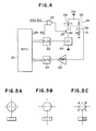
- Fig. 4 shows a laser light intensity control circuit.
- a microprocessor (MPU) 21 produces a laser on (LON) signal to turn on a transistor 27 and supplies a digital value to a D/A converter 22 to gradually increase the output of the D/A converter 22.
- a current I OP flowing through a laser diode 29 of a laser unit 28 gradually increases by a constant current circuit (CC) 24 so that a light intensity of the laser diode 29 increases.
- CC constant current circuit
- a laser beam from the laser diode 29 is emitted externally and also to an internal photo-diode 30.
- a photo-diode current I M which is proportional to the light intensity emitted externally flows.
- the output of the amplifier 25 is supplied to an A/D converter 23 where it is converted to a digital signal, which is read by a microprocessor 21.
- the microprocessor 21 increases the output of the D/A converter 22 until the output read by the micro-processor 21 reaches a predetermined value, when the output of the D/A converter 22 is fixed.
- the digital value currently applied to the D/A converter 22 is stored and the signal LON is turned off. In this manner, the laser light intensity is controlled.
- the microprocessor 21 applies the stored digital value to the D/A converter 22.
- a video (VDO) signal turns on and off a transistor 27 so that the laser diode 29 is turned on and off by a constant current pulse.
- the laser light intensity control system described above it is necessary to continuously emit the laser beam when the light intensity of the laser is detected.
- the emitted laser beam is necessarily directed to a photosensitive member. Accordingly, if toner deposits to the photo-sensitive member, the toner is wasted. Accordingly, it is necessary to control the process such that the toner is not developed.
- the process may be controlled prior to the actual print operation such that the toner is not developed and then the light intensity of the laser may be detected.
- continuous print operation because of the change of laser intensity by temperature, it is necessary to detect the laser light intensity between n-th printing and (n+1)th printing.
- a complex process control is required, and fast response of the development process is required.
- the photo-sensitive member is deteriorated by the wasteful laser beam irradiation to the photo-sensitive member.
- Embodiments of the present invention may overcome the disadvantages described above.
- Embodiments of the present invention may improve a beam recorder.
- Embodiments of the present invention may provide a beam recorder which can reproduce a high quality image.
- Embodiments of the present invention may provide an inexpensive beam recorder.
- Embodiments of the present invention may provide a long-life or durable beam recorder.
- Embodiments of the present invention may provide a beam recorder of a simple construction which attains a stable light intensity.
- Embodiments of the present invention may provide a recorder which prevents degradation of a record medium.
- Embodiments of the present invention may provide a beam recorder which prevents complex construction or complex program.
- Embodiments of the present invention may provide an image recorder which eliminates restriction on sequence control when the laser light beam is controlled, saves degradation factor and waste for process elements such as photo-sensitive member and developing unit, and improves performance such as fine control of the laser light beam so that higher quality of image is attained.
- a recorder of one embodiment of the present invention is an electrostatic recording type image recorder having an optical system for forming and scanning an image by a rotating polygon mirror and a laser beam emitted from a laser light source at least one of reflection planes of the rotating polygon mirror is a non-scan plane which does not form or scan the image and a laser light intensity is controlled while the laser beam is directed to the non-scan plane.
- Fig. 2 shows a construction of the laser beam printer of the present embodiment.
- a printer 1 After power-on, a printer 1 checkes if a temperature of a fixing unit 12 is proper, if sheets 13 are in a sheet cassette 14 and other internal status, and inform to an external host controller (not shown) whether a print operation is ready or not. When the print operation is ready, the host controller sends a start of print command to the printer 1 as required so that the printer l starts the print operation.
- a pre-exposure lamp 8 a primary charger 3 and a transfer unit 6 are activated and a polygon mirror 4 is rotated.
- a sheet 13 is fed from a sheet cassette 14 by a feed roller 9.
- a feed roller 9 When a leading edge of the sheet reaches a registration roller 10 and forms a loop, the feed of the sheet by the feed roller 9 is stopped and it stands by.
- the printer 1 requests to the host controller to send a sub-scan direction synchronization signal (VSYNC signal).
- VSYNC signal sub-scan direction synchronization signal
- the host controller sends the VSYNC signal and sends an image signal (VDO signal) in synchronism with a main scan direction synchronization signal (BD signal) from the printer 1.
- Figs. 1A and 3 show laser beam scan by the polygon mirror and a method for detecting a BD signal.
- a laser beam emitted from the laser 18 is scanned by the polygon mirror 4 to form a light image on the photo-sensivive drum 2 in the main scan direction (arrow).
- the laser beam is directed to the photo-sensor 20 by the mirror 19 so that a synchronization signal (BD signal) indicating the beam scan position is produced.
- the mirror 19 is arranged outside of an area in which the laser beam form the light image on the photo-sensitive drum 2.
- the photo-sensor 20 is arranged at an equal distance to that from the polygon mirror 4 to the photo-sensitive drum 2.
- the laser beam reflected by the polygon mirror 4 is focused onto the photo-sensitive drum 2 by the f ⁇ lens 17 and the mirror 16 of Fig. 2 to form the light image.
- the light image is then developed by the developing unit 5 into a toner image.
- the leading edge resigtration of the toner image and the sheet is effected by rotating the registration roller 10 in synchronism with the VSYNC signal.
- the toner image is transferred to the registered sheet by the transfer unit 6, and the sheet is fed to the fixing unit 12 by the feeder 11 where the toner image is fixed to the sheet.
- the sheet is then fed to the eject tray 15.
- the toner image which was not transferred to the sheet by the transfer unit 6 is scraped off the photo-sensitive drum 2 by the cleaner 7.
- a one-sheet print mode the laser 18 is deactivated at the end of formation of the light image on the photo-sensitive drum 2 and the rotation of the polygon mirror 4 is stopped.
- the photo-sensitive drum 2 is initialized, and after the sheet has been ejected, the rotation of the photo-sensitive drum 2 is stopped to terminate the print operation.
- a start of print command for the next sheet is requested to the host controller. In response to the start of print command, the sheet 13 is fed from the sheet cassette 14 so that the print operation is continued.
- Figs. 5A and 5B show conventional polygon mirror
- Fig. 5C shows the polygon mirror of the embodiment
- Fig. 1A also shows the polygon mirror 4 which is similar to that shown in Fig. 5C.
- the conventional polygon mirrors have six or eight reflection planes, all of which are micro-finished to reflect the laser beam at a high reflection factor.
- the polygon mirror of the embodiment has four planes as shown in Fig. 5C, and the planes A and C are not mirror-finished and are blank-coated (non-reflection coating) to reduce the reflection of laser beam as much as possible. Accordingly, it is the planes B and D that scan the beam for forming the image.
- the number of planes is 1/3 to 1/4 of that of the conventional polygon mirror and hence the polygon mirror of the embodiment must be rotated at a speed which is as 3 - 4 times high level that of the conventional polygon mirror.
- the print speed is 1/2 - 1/3 of that of the conventional printer.
- the rotation speed of the polygon mirror may be as 1 - 2 times high as that of the conventional mirror and this does not cause a practical problem.
- an image exposure system is used so that the toner is developed only at the area on the photo-sensitive drum to which the laser beam was irradiated. Accordingly, the planes A and C are black-coated in order to minimize the reflection of the laser beam.
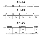
- Fig. 6A shows the BD signal produced when the planes A and C of the polygon mirror of Fig. 5C are not non-reflection planes.
- the BD signal produced by the polygon mirror of the embodiment shown in Figs. 1B and 6B, which has non-reflection planes A and C does not appear in periods ⁇ A and ⁇ C .
- the image is scanned on the photo-sensitive drum in periods T B and T D , as shown in Fig. 1C and 6C. Since the planes A and C are non-reflection planes, the photo-sensitive drum is not affected even if the laser is left activated at least during the periods ⁇ A and ⁇ C . Accordingly, the laser beam intensity may be controlled during the periods ⁇ A and ⁇ C .
- the waste of the toner by the prior art laser light intensity control, the complexity of process control to prevent the waste of the toner, and the degradation of the photo-sensitive member are prevented.
- the laser light intensity is controlled in the periods ⁇ A and ⁇ C of Fig. 6C. Since the laser beam is not reflected by the planes A and C, the BD signal cannot be directly obtained. Accordingly, it is necessary to separately produce a signal indicating the periods ⁇ A and ⁇ C or the starts of those periods.
- Fig. 7A shows a circuit diagram to produce the signal indicating the periods ⁇ A and ⁇ C
- Fig. 7B shows an operational timing chart.
- a microprocessor 21 sets a count to a counter 32.
- the microprocessor 21 control the light intensity as shown in Fig. 4 and controls the sequential operation of the printer.
- the count may be set to the counter 32 by other circuit than the microprocessor 21.
- the counter 32 is reset by the BD signal and then counts the above count by a clock signal CLK.
- the clock signal CLK may be one which is in synchronism with a record clock used to transfer the image signal.
- the count is selected such that an RC signal is produced after T1 time as shown in Fig. 7B.
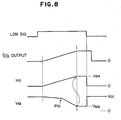
- Fig. 8 shows a timing chart for a sequence of laser light intensity control of the embodiment.
- the circuit shown in Fig. 4 is used as the laser light intensity control circuit, although other circuit may be used.
- the microprocessor 21 renders a LON signal to H-level to turn on a transistor 27, and supplies a digital value to a D/A converter 22, which produces a signal D/A as shown in Fig. 8.
- the output of the D/A converter 22 is gradually increased.
- a current I OP flowing through a laser diode 29 of a laser unit 28 gradually increases as shown in Fig. 8 by a constant current circuit 24 so that the light intensity of the laser diode 29 increases.
- the output beam of the laser diode 29 is also directed to a photo-diode 30 in the laser unit 28 and a photo-current I M which is proportioanl to the externally emitted laser beam intensity flows, and it is converted to a voltage V M by a resistor 31.and it is supplied to an amplifier 25.
- the output of the amplifier 25 is supplied to an A/D converter 23 where it is converted to a digital signal, which is read by the microprocessor 21.
- the microprocessor 21 stores the digital value applied to the D/A converter 22 when V M reaches V MS , and renders the LON signal to L-level and renders the output of the D/A converter 22 to zero to terminate the laser light intensity control.
- the microprocessor 21 renders the LON signal to the L-level and supplies to the D/A converter 22 the stored digital value for the predetermined light intensity.
- the VDO signal is driven by the constant current pulse.
- the laser light intensity control that is, the detection of the level of the signal V MS of Fig. 8 is effected in the periods ⁇ A and ⁇ C of Fig. 6C.
- the microprocessor 21 does not have the digital value to be supplied to the D/A converter 22 to produce the signal V MS , because the laser current I OPS necessary to produce the predetermined light intensity differs from laser unit 28 to laser unit 28.
- the microprocessor 21 before the image scan for the first print operation after the power-on, the microprocessor 21 must detects the V MS level.
- the laser current I OP is supplied to some extent so that the laser diode 29 emits light. Otherwise, the output of the photo-sensor 20 for detecting the BD signal cannot be produced and the periods ⁇ A and ⁇ C of Figs. 6B and 6C cannot be detected.
- the laser current which is large enough to produce the BD signal may be supplied instead of gradually increasing the laser current I OP from zero.
- a relation between the laser current of the laser unit 28 and the light intensity differs from unit to unit, and in a conventional semiconductor laser, the laser device may be deteriorated or broken if it is operated over a specified maximum light intensity.
- a laser A may emit a light below a maximum light intensity Pmax with the laser current I OP1 but a laser B may emit a light above the maximum light intensity Pmax with the laser current I OP1 .
- a laser C may emit a light which is too weak to produce the BD signal with the laser current I OP1 . Accordingly, it is difficult to determine the initial value of the laser current I OP in the first laser light beam control, and the initial value may be set.
- the BD signal is not produced until the predetermined light intensity is reached in the laser light intensity control.
- the first laser light intensity control after the power-on is effected after the start of the print operation and the start of the rotation of the polygon mirror 4, and the initial laser current I OP is set to zero. Accordingly, until the first BD signal is produced as the laser current I OP increases, the laser beam is directed to all planes A, B, C and D of the polygon mirror of Fig. 5C.
- the laser beam is irradiated to the photo-sensitive drum 2.
- the process condition is controlled such that the toner is not developed in spite of the irradiation of the laser beam to the photo-sensitive drum 2 until the BD signal has a normal period as the laser current I OP is increased, that is, until the polygon mirror 4 is rotated at a normal rotation speed.
- all outputs of the primary charger 3, the developing unit 5 and the transfer unit are turned off. Where the photo-sensitive drum 2 is initialized at the start of the rotation of the polygon mirror 4 and the laser light intensity control after the start of print operation in order to save wasteful time, only the primary charger 3 may be turned on.
- the first laser light intensity control after the power-on is effected. If the detection of the predetermined laser light intensity is completed before the BD signal having the normal period is produced, the laser is activated at the predetermined light intensity until the BD signal of the normal period is produced. If the predetermined laser light intensity is not attained when the BD signal having the normal period is produced, the laser light intensity control is continued in the periods ⁇ A and ⁇ C of Figs. 6B and 6C. In any case, when the laser light intensity control is completed and the BD signal having the normal period is produced, the laser is activated at the predetermined light intensity only at the timing to produce the BD signal until the actual print operation is started.
- the laser light intensity control in the print mode is effected in the periods ⁇ A and ⁇ C of Figs. 6B and 6C.
- the laser light intensity control may be effected between the n-th printing and the (n+1)th printing, that is, during the absence of the image scan, as well as during the image scan by utilizing the periods ⁇ A and ⁇ C of Figs. 6B and 6C. In this manner, the image quality is improved by compensating for the variation of the laser light intensity for each line scan.
- the digital value to be supplied to the D/A converter 22 to supply the predetermined laser current I OPS in the first laser light intensity control after the power-on may be stored in a RAM of the microprocessor 21.
- the start laser current I OPn at the n-th laser light intensity control may be I OPS (n-1) or I OPS (n-1)- ⁇ , where I OPS (n-1) is the laser current produced in the (n-1)th control. This is illustrated in Fig. 12.
- Fig. 9A shows a polygon mirror in another embodiment.
- the planes A and C are round so that the laser beams directed to the planes A and C are reflected to areas other than the photo-sensitive drum and the BD sensor.
- Fig. 9B shows a polygon mirror in other embodiment.
- the planes A and C are inclined relative to the planes B and D so that the laser beam is not reflected to the photo-sensitive drum or the BD sensor.
- Figs. 10A and 10B show polygon mirrors having more than four planes.
- the reflection plane and the non-reflection plane alternatively appear.
- the laser light intensity control may be effected in either scan period or non-scan period of the image, or it may be continuously effected to improve the lifetimes of the apparatus and laser. Alternatively, it may be effected at any time such as periodically, at every predetermined number of printed sheets, or when a change in a temperature in a vicinity of the laser is detected.
- the laser light intensity control is effected by continuously activating the laser until the BD signal has the normal period at the start of rotation of the polygon mirror.
- the laser light intensity control in the periods ⁇ A and ⁇ C may be started at this moment.
- a circuit for generating a signal for assuring the periods ⁇ A and ⁇ C to be one half of the BD period may be provided to control the laser light intensity in the signal period.
Landscapes
- Engineering & Computer Science (AREA)
- Multimedia (AREA)
- Signal Processing (AREA)
- Physics & Mathematics (AREA)
- Optics & Photonics (AREA)
- General Physics & Mathematics (AREA)
- General Engineering & Computer Science (AREA)
- Theoretical Computer Science (AREA)
- Facsimile Scanning Arrangements (AREA)
- Mechanical Optical Scanning Systems (AREA)
- Fax Reproducing Arrangements (AREA)
- Dot-Matrix Printers And Others (AREA)
- Laser Beam Printer (AREA)
Applications Claiming Priority (2)
| Application Number | Priority Date | Filing Date | Title |
|---|---|---|---|
| JP62203020A JPS6446724A (en) | 1987-08-17 | 1987-08-17 | Image recorder |
| JP203020/87 | 1987-08-17 |
Publications (3)
| Publication Number | Publication Date |
|---|---|
| EP0304276A2 true EP0304276A2 (de) | 1989-02-22 |
| EP0304276A3 EP0304276A3 (en) | 1989-05-03 |
| EP0304276B1 EP0304276B1 (de) | 1993-11-10 |
Family
ID=16467017
Family Applications (1)
| Application Number | Title | Priority Date | Filing Date |
|---|---|---|---|
| EP88307597A Expired - Lifetime EP0304276B1 (de) | 1987-08-17 | 1988-08-16 | Strahlaufzeichnungsgerät |
Country Status (4)
| Country | Link |
|---|---|
| US (1) | US4935615A (de) |
| EP (1) | EP0304276B1 (de) |
| JP (1) | JPS6446724A (de) |
| DE (1) | DE3885541T2 (de) |
Cited By (3)
| Publication number | Priority date | Publication date | Assignee | Title |
|---|---|---|---|---|
| EP0494645A3 (en) * | 1991-01-09 | 1993-02-03 | Dainippon Screen Mfg. Co., Ltd. | Light beam scanning system |
| EP0649247A3 (de) * | 1988-09-06 | 1995-07-19 | Canon Kk | Belichtungsstärkesteuergerät. |
| EP0880274A3 (de) * | 1997-03-20 | 1999-12-29 | Lexmark International, Inc. | Bilderzeugungsgerät und Verfahren zur Laserkalibrierung |
Families Citing this family (10)
| Publication number | Priority date | Publication date | Assignee | Title |
|---|---|---|---|---|
| US4899176A (en) * | 1988-08-25 | 1990-02-06 | Minnesota Mining And Manufacturing Company | Method of reducing average data rate in rotating mirror laser recorder |
| EP0416832B1 (de) * | 1989-09-07 | 1996-07-10 | Canon Kabushiki Kaisha | Bilddarstellungsgerät |
| JPH03201492A (ja) * | 1989-12-28 | 1991-09-03 | Toshiba Corp | レーザ発振器の光量制御装置 |
| JPH03202368A (ja) * | 1989-12-28 | 1991-09-04 | Toshiba Corp | レーザ発振器の光量制御装置 |
| JPH03245116A (ja) * | 1990-02-23 | 1991-10-31 | Toshiba Corp | 光学装置及びこの光学装置が組込まれる画像形成装置或いは画像情報読取装置 |
| JPH1097392A (ja) | 1996-09-19 | 1998-04-14 | Canon Inc | 印刷制御装置および印刷制御方法およびコンピュータが読み出し可能なプログラムを格納した記憶媒体 |
| JP3610180B2 (ja) | 1997-02-18 | 2005-01-12 | キヤノン株式会社 | 画像形成装置およびその方法 |
| JP2000218865A (ja) | 1998-11-25 | 2000-08-08 | Canon Inc | レ―ザ駆動装置とその駆動方法及びそれを用いた画像形成装置 |
| JP2006123480A (ja) * | 2004-11-01 | 2006-05-18 | Funai Electric Co Ltd | 画像形成装置 |
| JP2009137189A (ja) * | 2007-12-07 | 2009-06-25 | Brother Ind Ltd | 画像形成装置 |
Family Cites Families (12)
| Publication number | Priority date | Publication date | Assignee | Title |
|---|---|---|---|---|
| US2476503A (en) * | 1944-10-04 | 1949-07-19 | Maytum James Archibald | Continuous feed kinematographic apparatus |
| US3287559A (en) * | 1963-10-04 | 1966-11-22 | Barnes Eng Co | Infrared thermogram camera and scanning means therefor |
| FR2050531A5 (de) * | 1969-06-17 | 1971-04-02 | Fabiani Henri | |
| GB1343351A (en) * | 1971-10-27 | 1974-01-10 | Ferranti Ltd | Tracking of objects |
| US3944323A (en) * | 1974-12-23 | 1976-03-16 | Xerox Corporation | Variable spot size scanning system |
| JPS5190829A (de) * | 1975-02-07 | 1976-08-09 | ||
| FR2601464B1 (fr) * | 1979-08-31 | 1989-01-13 | Comp Generale Electricite | Dispositif de balayage alternatif d'un plan par un faisceau lumineux |
| US4443695A (en) * | 1980-01-25 | 1984-04-17 | Canon Kabushiki Kaisha | Apparatus for controlling the quantity of light |
| JPS5977406A (ja) * | 1982-10-25 | 1984-05-02 | Fujitsu Ltd | 回転多面鏡の製造方法 |
| JPS59146069A (ja) * | 1983-02-08 | 1984-08-21 | Canon Inc | 光源安定化装置 |
| JPS6050509A (ja) * | 1983-08-31 | 1985-03-20 | Hitachi Ltd | 光ビ−ム走査型画像入力装置 |
| JPS60149018A (ja) * | 1984-01-13 | 1985-08-06 | Nec Corp | レ−ザビ−ム走査装置 |
-
1987
- 1987-08-17 JP JP62203020A patent/JPS6446724A/ja active Pending
-
1988
- 1988-08-15 US US07/232,168 patent/US4935615A/en not_active Expired - Lifetime
- 1988-08-16 EP EP88307597A patent/EP0304276B1/de not_active Expired - Lifetime
- 1988-08-16 DE DE88307597T patent/DE3885541T2/de not_active Expired - Fee Related
Cited By (4)
| Publication number | Priority date | Publication date | Assignee | Title |
|---|---|---|---|---|
| EP0649247A3 (de) * | 1988-09-06 | 1995-07-19 | Canon Kk | Belichtungsstärkesteuergerät. |
| EP0494645A3 (en) * | 1991-01-09 | 1993-02-03 | Dainippon Screen Mfg. Co., Ltd. | Light beam scanning system |
| EP0880274A3 (de) * | 1997-03-20 | 1999-12-29 | Lexmark International, Inc. | Bilderzeugungsgerät und Verfahren zur Laserkalibrierung |
| KR100567933B1 (ko) * | 1997-03-20 | 2006-11-10 | 렉스마크 인터내셔널, 인코포레이티드 | 광학디바이스의램프업주기동안레이저캘리브레이션을이용하는이미지형성장치 |
Also Published As
| Publication number | Publication date |
|---|---|
| US4935615A (en) | 1990-06-19 |
| DE3885541T2 (de) | 1994-03-24 |
| EP0304276B1 (de) | 1993-11-10 |
| EP0304276A3 (en) | 1989-05-03 |
| JPS6446724A (en) | 1989-02-21 |
| DE3885541D1 (de) | 1993-12-16 |
Similar Documents
| Publication | Publication Date | Title |
|---|---|---|
| EP0412036B1 (de) | Bildpunktpositionierungskorrektur in dem Abtastbereich eines Mehrstrahl-Laserabtastsystemes | |
| US4935615A (en) | Light intensity control for light beam recorder | |
| US5416505A (en) | Image drawing apparatus | |
| US6646668B2 (en) | Image forming apparatus for maintaining a constant beam scanning state | |
| US4967284A (en) | Image forming apparatus and method of controlling output of semiconductor laser | |
| US5128699A (en) | Image recording apparatus capable of changing dot density and dot size | |
| JP3234246B2 (ja) | 画像形成装置 | |
| US5561285A (en) | Image forming apparatus and light quantity control device having a light emission mode control means | |
| US5347298A (en) | Exposure control device for use in electrophotographic printing apparatus | |
| US7187397B2 (en) | Light beam scanning apparatus | |
| US6344866B1 (en) | Light beam scanner unit with passing position and power control and image forming apparatus | |
| JPH05304595A (ja) | レーザビーム走査装置 | |
| US5596444A (en) | Optical apparatus having laser beam diameter variable according to image data | |
| JPH11105335A (ja) | 画像形成装置と半導体レーザーapc回路 | |
| JP4235292B2 (ja) | 画像形成装置 | |
| JP3710389B2 (ja) | 画像形成装置 | |
| JPH06255172A (ja) | 画像形成装置 | |
| JP2860190B2 (ja) | 印刷装置及び印刷制御装置 | |
| JP2952330B2 (ja) | 画像形成装置および光量制御方法 | |
| JP4474028B2 (ja) | 画像形成装置 | |
| JP2775745B2 (ja) | 電子写真装置の帯電制御方法 | |
| JPS63301075A (ja) | レ−ザビ−ムプリンタの光量調整装置 | |
| JP2002067377A (ja) | 画像形成装置及びその制御方法 | |
| JPH04173266A (ja) | 画像形成装置 | |
| JPH04136876A (ja) | レーザプリンタのビームパワー制御方法 |
Legal Events
| Date | Code | Title | Description |
|---|---|---|---|
| PUAI | Public reference made under article 153(3) epc to a published international application that has entered the european phase |
Free format text: ORIGINAL CODE: 0009012 |
|
| AK | Designated contracting states |
Kind code of ref document: A2 Designated state(s): DE FR GB IT |
|
| PUAL | Search report despatched |
Free format text: ORIGINAL CODE: 0009013 |
|
| RHK1 | Main classification (correction) |
Ipc: G03G 15/32 |
|
| AK | Designated contracting states |
Kind code of ref document: A3 Designated state(s): DE FR GB IT |
|
| 17P | Request for examination filed |
Effective date: 19890927 |
|
| 17Q | First examination report despatched |
Effective date: 19920121 |
|
| ITTA | It: last paid annual fee | ||
| ITF | It: translation for a ep patent filed | ||
| GRAA | (expected) grant |
Free format text: ORIGINAL CODE: 0009210 |
|
| AK | Designated contracting states |
Kind code of ref document: B1 Designated state(s): DE FR GB IT |
|
| REF | Corresponds to: |
Ref document number: 3885541 Country of ref document: DE Date of ref document: 19931216 |
|
| ET | Fr: translation filed | ||
| PLBE | No opposition filed within time limit |
Free format text: ORIGINAL CODE: 0009261 |
|
| STAA | Information on the status of an ep patent application or granted ep patent |
Free format text: STATUS: NO OPPOSITION FILED WITHIN TIME LIMIT |
|
| 26N | No opposition filed | ||
| REG | Reference to a national code |
Ref country code: GB Ref legal event code: IF02 |
|
| PGFP | Annual fee paid to national office [announced via postgrant information from national office to epo] |
Ref country code: GB Payment date: 20050705 Year of fee payment: 18 |
|
| PGFP | Annual fee paid to national office [announced via postgrant information from national office to epo] |
Ref country code: FR Payment date: 20050819 Year of fee payment: 18 |
|
| PGFP | Annual fee paid to national office [announced via postgrant information from national office to epo] |
Ref country code: DE Payment date: 20051024 Year of fee payment: 18 |
|
| PGFP | Annual fee paid to national office [announced via postgrant information from national office to epo] |
Ref country code: IT Payment date: 20060831 Year of fee payment: 19 |
|
| PG25 | Lapsed in a contracting state [announced via postgrant information from national office to epo] |
Ref country code: DE Free format text: LAPSE BECAUSE OF NON-PAYMENT OF DUE FEES Effective date: 20070301 |
|
| GBPC | Gb: european patent ceased through non-payment of renewal fee |
Effective date: 20060816 |
|
| REG | Reference to a national code |
Ref country code: FR Ref legal event code: ST Effective date: 20070430 |
|
| PG25 | Lapsed in a contracting state [announced via postgrant information from national office to epo] |
Ref country code: GB Free format text: LAPSE BECAUSE OF NON-PAYMENT OF DUE FEES Effective date: 20060816 |
|
| PG25 | Lapsed in a contracting state [announced via postgrant information from national office to epo] |
Ref country code: FR Free format text: LAPSE BECAUSE OF NON-PAYMENT OF DUE FEES Effective date: 20060831 |
|
| PG25 | Lapsed in a contracting state [announced via postgrant information from national office to epo] |
Ref country code: IT Free format text: LAPSE BECAUSE OF NON-PAYMENT OF DUE FEES Effective date: 20070816 |