EP0305014A2 - Gerüst mit Pfosten, Riegel und an diesen Riegeln befestigten Gerüstplatten - Google Patents
Gerüst mit Pfosten, Riegel und an diesen Riegeln befestigten Gerüstplatten Download PDFInfo
- Publication number
- EP0305014A2 EP0305014A2 EP88201809A EP88201809A EP0305014A2 EP 0305014 A2 EP0305014 A2 EP 0305014A2 EP 88201809 A EP88201809 A EP 88201809A EP 88201809 A EP88201809 A EP 88201809A EP 0305014 A2 EP0305014 A2 EP 0305014A2
- Authority
- EP
- European Patent Office
- Prior art keywords
- catch
- cross member
- platform
- claw
- cross members
- Prior art date
- Legal status (The legal status is an assumption and is not a legal conclusion. Google has not performed a legal analysis and makes no representation as to the accuracy of the status listed.)
- Withdrawn
Links
- 210000000078 claw Anatomy 0.000 claims abstract description 53
- 238000010276 construction Methods 0.000 claims abstract description 16
- 230000000694 effects Effects 0.000 claims description 2
- 238000007689 inspection Methods 0.000 description 1
- 238000012986 modification Methods 0.000 description 1
- 230000004048 modification Effects 0.000 description 1
- 239000011120 plywood Substances 0.000 description 1
- 230000002787 reinforcement Effects 0.000 description 1
Images


Classifications
-
- E—FIXED CONSTRUCTIONS
- E04—BUILDING
- E04G—SCAFFOLDING; FORMS; SHUTTERING; BUILDING IMPLEMENTS OR AIDS, OR THEIR USE; HANDLING BUILDING MATERIALS ON THE SITE; REPAIRING, BREAKING-UP OR OTHER WORK ON EXISTING BUILDINGS
- E04G1/00—Scaffolds primarily resting on the ground
- E04G1/15—Scaffolds primarily resting on the ground essentially comprising special means for supporting or forming platforms; Platforms
- E04G1/154—Non-detachably fixed and secured connections between platform and scaffold
-
- E—FIXED CONSTRUCTIONS
- E04—BUILDING
- E04G—SCAFFOLDING; FORMS; SHUTTERING; BUILDING IMPLEMENTS OR AIDS, OR THEIR USE; HANDLING BUILDING MATERIALS ON THE SITE; REPAIRING, BREAKING-UP OR OTHER WORK ON EXISTING BUILDINGS
- E04G7/00—Connections between parts of the scaffold
- E04G7/02—Connections between parts of the scaffold with separate coupling elements
- E04G7/28—Clips or connections for securing boards
Definitions
- the invention relates to a scaffold construction comprising uprights and cross members connected to the uprights and keeping them spaced apart, on which cross members the open ends of substantially U-shaped claws may be positioned from above, said claws being connected to a platform and being automatically locked with respect to the cross members after mounting.
- Such a scaffold construction is known from: Dutch Patent Application No. 86 01564, laid open to public inspection.
- locking is achieved in that a part of the upper surface of the cross members, which are circular in cross-section, will come to rest into recesses of the U-shaped claws while the substantially vertical parts of the claws are at some distance from the relevant cross member and the most outwardly positioned leg of the claw is slightly curved inwardly such that it will be within the outer circumference of the relevant cross-seciton, as seen in vertical direction. If now an upwardly directed movement is exerted on the claw the inwardly curved part of it will come to rest against the cross member, so that it is prevented that the claw leaves the cross member.
- a disadvantage of this known construction is not only that the internal shape of the claws should comply with very high demands, but it is especially disadvantageous that on mounting and dismantling of a platform, this has to be displaced to and fro in a particular manner in order to be able to release the claws from the cross members on lifting the platform.
- a further disadvantage of the known construction is also that the locking of the claws is not absolutely safe and that there is such a play present between the main part of the claw and the cross member that no substantial forces exerted in a horizontal direction on the platform, can be transferred to the cross member without more.
- the platform can not act for stiffening the scaffold construction in the plane of the platform.
- the invention removes these disadvantages and provides to that end that for achieving the locking a catch is present, which is displaceably embraced by a U-shaped strap connected to the platform, said catch being shaped such that when lowering a claw of a platform onto a cross member, the catch will be lifted from the locking position by the cross member and will resume the locking position once the claw rests on the cross member.
- the catch When the platform has to be removed the catch simply may be pressed manually to a higher position in which it does not lock the platform anymore.
- the catch would be reset into its locking position by means of a spring, preferably the catch will be made such that it will occupy the locking position under the effect of its own weight.
- the catch is formed by a twice bended strip with substantially the shape of a U, the legs of which are making an obtuse angle with the body, the strip being provided with extending parts at both ends so that the catch can not be removed from the strap which is connected to the platform.
- the catch and the strap by which it is embraced are executed such that the catch may remain in the unlocked position as long as no tilting movement or a blow is exerted on the platform.
- the claw may have the shape of a U, of which the inner surfaces of the legs are extending substantially parallel to each other, in particular it may be provided that the claw is having an internal shape adapted to the circular shape of the cross member in such a way that the claw is having a widened inlet opening but that there is no or substantially no play present between the claw and the cross member in the ultimate position.
- the claw is having a cavity adapted to the largest diameter of the cross member applied, said cavity having a recess for receiving a cross member with a diameter which is substantially smaller than the first mentioned diameter.
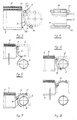
- the scaffold construction shown in Figs. 1 and 2 consists of the uprights 1, provided with the junctions 2 and being mutually connected by means of the cross members 3.
- the cross members 3 are mutually connected by means of platforms 4, the claws 5 of which are mounted on the cross members 3.
- diagonally extending braces 6 may be used to obtain adequate stability of the scaffold construction.
- the claws 5, connected to a platform 4 are staggered in respect of each other so that the claws of two platforms 4 may be mounted on one cross member 3.
- the platforms 4 are formed by the frame 7, which is provided with a locking device 8 at each one of its ends 7a.
- the locking devices 8 are staggered at the ends.
- the frame 7 is connected with a plywood slab 9, such that the platform 4 represents a rigid entity in its plane.
- a reinforcement 10 is mounted under the slab 9 at the place of the locking device 8, as in particular appears from Fig. 3 too.
- the locking device 8 is formed by a U-strap 11, welded on the end 7a of the frame 7, by which a catch 12 is displaceably embraced.
- the catch 12 is formed by a substantially U-shaped strip, the body 13 of which is provided with the legs 14 and 15.
- the leg 14 is connected to the lower pin 16 and the leg 15 to the upper pin 17.
- the pins 16 and 17 extend outside the strap 11 so that the catch 12 can not be removed from the strap 11. In general the catch 12 will assume the position as shown in Fig. 3 by its own weight.
- the catch 12 can be brought into the position as shown in Fig. 7, so that the claw 5 of the platform can be released from the cross member 3. This position is shown in Fig. 8.
- the catch When tilting the platform from the position shown in Fig. 8, or on touching the catch 12, the catch will very easily fall back towards the position as shown in Figs. 3 and 5.
- the catch 12 will maintain the position as shown in Fig. 8, so that after mounting of the platform 4 the catch 12 will always be in the locking position.
- the inner walls of the legs extend parallel to each other.
- some play should be present between the claw 5 and the cross member 3. Though this play may be kept small, it nevertheless will result in a less stable connection between a platform 4 and a cross member 3.
- the claw 18 is composed of the inlet section 19, the section 20 with a radius of curvature R corresponding with the radius of the cross member 3, the section 21 having a radius of curvature S corresponding with the radius of a cross member with a smaller diameter, a section 22 with the radius of curvature R again and a substantially straight section 23.
- a claw 18, shaped in this manner, can be easily mounted on the cross member 3 while thereafter the claw can no longer be displaced in horizontal direction with respect to the cross member.
- the claw 18 can be applied also when cross members with a smaller diameter are used.
- Fig. 9 the platform positioned next to the platform 4 is shown in dash-lines as well as the claw 18 connected to it. For better clarity the locking device 8 has been deleted from Fig. 9.
Landscapes
- Engineering & Computer Science (AREA)
- Architecture (AREA)
- Mechanical Engineering (AREA)
- Civil Engineering (AREA)
- Structural Engineering (AREA)
- Ladders (AREA)
Applications Claiming Priority (2)
| Application Number | Priority Date | Filing Date | Title |
|---|---|---|---|
| NL8702026A NL8702026A (nl) | 1987-08-28 | 1987-08-28 | Steigerconstructie bestaande uit staanders, kortelingen, en met de kortelingen verbonden platforms. |
| NL8702026 | 1987-08-28 |
Publications (2)
| Publication Number | Publication Date |
|---|---|
| EP0305014A2 true EP0305014A2 (de) | 1989-03-01 |
| EP0305014A3 EP0305014A3 (de) | 1989-04-26 |
Family
ID=19850516
Family Applications (1)
| Application Number | Title | Priority Date | Filing Date |
|---|---|---|---|
| EP88201809A Withdrawn EP0305014A3 (de) | 1987-08-28 | 1988-08-25 | Gerüst mit Pfosten, Riegel und an diesen Riegeln befestigten Gerüstplatten |
Country Status (2)
| Country | Link |
|---|---|
| EP (1) | EP0305014A3 (de) |
| NL (1) | NL8702026A (de) |
Cited By (9)
| Publication number | Priority date | Publication date | Assignee | Title |
|---|---|---|---|---|
| EP0407680A1 (de) * | 1989-07-12 | 1991-01-16 | TRAVHYDRO ECHAFAUDAGES Société Anonyme | Verfahren zum Verbinden einer vorgefertigten Gerüstbühne mit einer horizontalen Traverse, und vorgefertigte Gerüstbühne dazu |
| FR2690942A1 (fr) * | 1992-05-06 | 1993-11-12 | Casaccia Rene | Caillebottis à fixation incorporée sur élément tubulaire. |
| DE9314353U1 (de) * | 1993-09-22 | 1993-12-16 | Hans-J. Gebauer GmbH, 56727 Mayen | Arbeitsbühne, vorzugsweise Gerüst zur Einrüstung von Fassaden o.dgl. |
| EP0637660A1 (de) * | 1993-08-02 | 1995-02-08 | Gerald Merkel | Aushebesicherung für Gerüstbelagteile |
| WO1996001350A1 (de) * | 1994-07-01 | 1996-01-18 | Krause-Werk Gmbh & Co. Kg | Belagbühne |
| EP0892126A1 (de) * | 1997-07-14 | 1999-01-20 | Alusuisse Technology & Management AG | Begehbare Planke, insbesondere Planke für den Gerüstbau, mit Halteorgan für ein Gegenelement |
| US5915497A (en) * | 1994-11-11 | 1999-06-29 | Krause-Werk Gmbh & Co. Kg | Working platform |
| FR2781534A1 (fr) * | 1998-07-21 | 2000-01-28 | Entrepose Echafaudages | Dispositif de verrouillage sur une traverse horizontale |
| WO2000061891A1 (en) * | 1999-04-09 | 2000-10-19 | Pluseight Technology Ab | Locking device for scaffolding elements |
Family Cites Families (4)
| Publication number | Priority date | Publication date | Assignee | Title |
|---|---|---|---|---|
| GB2058189B (en) * | 1979-08-15 | 1983-10-05 | Gkn Mills Building Serv | Releasable fastenings |
| DE3014212A1 (de) * | 1980-04-14 | 1981-10-15 | Plettac Gmbh Stahlbau Und Gesenkschmiede, 5970 Plettenberg | Baugeruest, insbesondere fahrgeruest |
| NL178709C (nl) * | 1981-01-21 | 1986-05-01 | Woodland B V | Inrichting voor het bevestigen van een voorwerp met een vlak aan een staaf. |
| GB2127086B (en) * | 1982-08-20 | 1986-01-29 | Alto Systems Ltd | Automatic latch for use in scaffolding structures |
-
1987
- 1987-08-28 NL NL8702026A patent/NL8702026A/nl not_active Application Discontinuation
-
1988
- 1988-08-25 EP EP88201809A patent/EP0305014A3/de not_active Withdrawn
Cited By (11)
| Publication number | Priority date | Publication date | Assignee | Title |
|---|---|---|---|---|
| EP0407680A1 (de) * | 1989-07-12 | 1991-01-16 | TRAVHYDRO ECHAFAUDAGES Société Anonyme | Verfahren zum Verbinden einer vorgefertigten Gerüstbühne mit einer horizontalen Traverse, und vorgefertigte Gerüstbühne dazu |
| FR2690942A1 (fr) * | 1992-05-06 | 1993-11-12 | Casaccia Rene | Caillebottis à fixation incorporée sur élément tubulaire. |
| EP0637660A1 (de) * | 1993-08-02 | 1995-02-08 | Gerald Merkel | Aushebesicherung für Gerüstbelagteile |
| DE9314353U1 (de) * | 1993-09-22 | 1993-12-16 | Hans-J. Gebauer GmbH, 56727 Mayen | Arbeitsbühne, vorzugsweise Gerüst zur Einrüstung von Fassaden o.dgl. |
| WO1996001350A1 (de) * | 1994-07-01 | 1996-01-18 | Krause-Werk Gmbh & Co. Kg | Belagbühne |
| RU2140506C1 (ru) * | 1994-07-01 | 1999-10-27 | Краузе-Верк Гмбх Унд Ко. Кг | Настил-площадка |
| US5915497A (en) * | 1994-11-11 | 1999-06-29 | Krause-Werk Gmbh & Co. Kg | Working platform |
| EP0892126A1 (de) * | 1997-07-14 | 1999-01-20 | Alusuisse Technology & Management AG | Begehbare Planke, insbesondere Planke für den Gerüstbau, mit Halteorgan für ein Gegenelement |
| FR2781534A1 (fr) * | 1998-07-21 | 2000-01-28 | Entrepose Echafaudages | Dispositif de verrouillage sur une traverse horizontale |
| WO2000061891A1 (en) * | 1999-04-09 | 2000-10-19 | Pluseight Technology Ab | Locking device for scaffolding elements |
| US6530456B1 (en) | 1999-04-09 | 2003-03-11 | Pluseight Technology Ab | Locking device for scaffolding elements |
Also Published As
| Publication number | Publication date |
|---|---|
| EP0305014A3 (de) | 1989-04-26 |
| NL8702026A (nl) | 1989-03-16 |
Similar Documents
| Publication | Publication Date | Title |
|---|---|---|
| KR930001033B1 (ko) | 지주의 연결방법 및 지주장치 | |
| US3420557A (en) | Builder's scaffolding | |
| KR100571717B1 (ko) | 포크 몸체 | |
| EP0305014A2 (de) | Gerüst mit Pfosten, Riegel und an diesen Riegeln befestigten Gerüstplatten | |
| ES2596504T3 (es) | Andamio de fachada | |
| EP0457377A1 (de) | Stahlrohrstütze für Bauschalungen | |
| US5112155A (en) | Connector for assembling components of scaffolding | |
| US7048093B2 (en) | Coupling device for scaffoldings | |
| US4037382A (en) | Scaffolding | |
| KR20140079461A (ko) | 비계용 커플링 부재 | |
| US9260873B1 (en) | Truss member and truss connector | |
| AU2021431649A1 (en) | Connection device, ceiling formwork system having a connection device, and use of a connection device | |
| US5660006A (en) | Wall support device | |
| JP4387568B2 (ja) | 張り出しブラケットなどの仮設足場部材 | |
| EP0473394B1 (de) | Gerüststrukturen | |
| GB2037928A (en) | Cross-member for Scaffolding | |
| WO1996006251A1 (en) | A device for a scaffold | |
| US2891820A (en) | Scaffold structure | |
| EP0427448B1 (de) | Baugerüst | |
| EP0067159A1 (de) | Vorrichtung für eine abnehmbare halterung einer arbeitsplattform an einer wand oder dergleichen | |
| JPH0583191U (ja) | ジョイントピンの抜け止め具 | |
| US3339951A (en) | Connector unit for scaffold | |
| JPS5810452Y2 (ja) | 動物飼育ケ−ジの開閉網ロツク金具 | |
| KR200218580Y1 (ko) | 건설용 중장비에 설치되는 사다리 구조체 | |
| JP2566529Y2 (ja) | 組立式仮設支持枠用筋交い |
Legal Events
| Date | Code | Title | Description |
|---|---|---|---|
| PUAI | Public reference made under article 153(3) epc to a published international application that has entered the european phase |
Free format text: ORIGINAL CODE: 0009012 |
|
| AK | Designated contracting states |
Kind code of ref document: A2 Designated state(s): AT BE CH DE ES FR GB GR IT LI LU NL SE |
|
| PUAL | Search report despatched |
Free format text: ORIGINAL CODE: 0009013 |
|
| AK | Designated contracting states |
Kind code of ref document: A3 Designated state(s): AT BE CH DE ES FR GB GR IT LI LU NL SE |
|
| STAA | Information on the status of an ep patent application or granted ep patent |
Free format text: STATUS: THE APPLICATION IS DEEMED TO BE WITHDRAWN |
|
| 18D | Application deemed to be withdrawn |
Effective date: 19900103 |