EP0407680A1 - Verfahren zum Verbinden einer vorgefertigten Gerüstbühne mit einer horizontalen Traverse, und vorgefertigte Gerüstbühne dazu - Google Patents
Verfahren zum Verbinden einer vorgefertigten Gerüstbühne mit einer horizontalen Traverse, und vorgefertigte Gerüstbühne dazu Download PDFInfo
- Publication number
- EP0407680A1 EP0407680A1 EP89870109A EP89870109A EP0407680A1 EP 0407680 A1 EP0407680 A1 EP 0407680A1 EP 89870109 A EP89870109 A EP 89870109A EP 89870109 A EP89870109 A EP 89870109A EP 0407680 A1 EP0407680 A1 EP 0407680A1
- Authority
- EP
- European Patent Office
- Prior art keywords
- support
- horizontal
- opening
- lock
- prefabricated floor
- Prior art date
- Legal status (The legal status is an assumption and is not a legal conclusion. Google has not performed a legal analysis and makes no representation as to the accuracy of the status listed.)
- Granted
Links
- 238000000034 method Methods 0.000 title description 4
- 239000000725 suspension Substances 0.000 claims abstract description 18
- 238000010276 construction Methods 0.000 claims abstract description 8
- XEEYBQQBJWHFJM-UHFFFAOYSA-N Iron Chemical compound [Fe] XEEYBQQBJWHFJM-UHFFFAOYSA-N 0.000 description 6
- 239000002184 metal Substances 0.000 description 5
- 229910052751 metal Inorganic materials 0.000 description 5
- 229910052742 iron Inorganic materials 0.000 description 3
- 229910001335 Galvanized steel Inorganic materials 0.000 description 1
- 240000008042 Zea mays Species 0.000 description 1
- 230000000593 degrading effect Effects 0.000 description 1
- 230000001627 detrimental effect Effects 0.000 description 1
- 230000008014 freezing Effects 0.000 description 1
- 238000007710 freezing Methods 0.000 description 1
- 239000008397 galvanized steel Substances 0.000 description 1
- 230000004048 modification Effects 0.000 description 1
- 238000012986 modification Methods 0.000 description 1
- 238000010079 rubber tapping Methods 0.000 description 1
- 239000003351 stiffener Substances 0.000 description 1
Images

Classifications
-
- E—FIXED CONSTRUCTIONS
- E04—BUILDING
- E04G—SCAFFOLDING; FORMS; SHUTTERING; BUILDING IMPLEMENTS OR AIDS, OR THEIR USE; HANDLING BUILDING MATERIALS ON THE SITE; REPAIRING, BREAKING-UP OR OTHER WORK ON EXISTING BUILDINGS
- E04G7/00—Connections between parts of the scaffold
- E04G7/30—Scaffolding bars or members with non-detachably fixed coupling elements
- E04G7/302—Scaffolding bars or members with non-detachably fixed coupling elements for connecting crossing or intersecting bars or members
- E04G7/303—Scaffolding bars or members with non-detachably fixed coupling elements for connecting crossing or intersecting bars or members the added coupling elements are only fixed at one of the bars or members to connect
- E04G7/305—Scaffolding bars or members with non-detachably fixed coupling elements for connecting crossing or intersecting bars or members the added coupling elements are only fixed at one of the bars or members to connect without tying means for connecting the bars or members
-
- E—FIXED CONSTRUCTIONS
- E04—BUILDING
- E04G—SCAFFOLDING; FORMS; SHUTTERING; BUILDING IMPLEMENTS OR AIDS, OR THEIR USE; HANDLING BUILDING MATERIALS ON THE SITE; REPAIRING, BREAKING-UP OR OTHER WORK ON EXISTING BUILDINGS
- E04G1/00—Scaffolds primarily resting on the ground
- E04G1/15—Scaffolds primarily resting on the ground essentially comprising special means for supporting or forming platforms; Platforms
- E04G1/154—Non-detachably fixed and secured connections between platform and scaffold
-
- E—FIXED CONSTRUCTIONS
- E04—BUILDING
- E04G—SCAFFOLDING; FORMS; SHUTTERING; BUILDING IMPLEMENTS OR AIDS, OR THEIR USE; HANDLING BUILDING MATERIALS ON THE SITE; REPAIRING, BREAKING-UP OR OTHER WORK ON EXISTING BUILDINGS
- E04G7/00—Connections between parts of the scaffold
- E04G7/02—Connections between parts of the scaffold with separate coupling elements
- E04G7/28—Clips or connections for securing boards
Definitions
- the present invention relates to a prefabricated floor provided with safety fastening devices to allow fixing on horizontal crosspieces of scaffolding or a similar construction with excellent fixing stability.
- a metal floor has the advantage over a traditional wooden floor of being lighter and less degrading.
- a metal floor is usually made of a folded metal sheet and / or stamped to form a resistant box.
- Each metal floor is provided with fasteners for suspension and fixing on horizontal sleepers of a construction, for example a scaffolding or a framework.
- the fasteners are usually legs intended to be placed on a horizontal crosspiece in order to thus suspend the floor.
- This method of attachment is not opposed to lifting (for example by the wind) or play which are detrimental to the stability of the floor and the safety of site personnel, people and property. This method of attachment therefore does not ensure locking on the cross-member. An imbalance of the load on the floor can therefore produce a movement of the floor and constitute a danger for site personnel.
- the invention aims to remedy the drawbacks of the known technique. Its purpose is to provide a prefabricated floor having fastening devices which not only ensure easy locking and unlocking, but also locking. reliable and automatic, capable of guaranteeing perfect seat stability on the floor.
- a floor consisting of a profile, each end of the profile being closed by a support comprising a vertical member on which are fixed two suspension hooks intended to fit a horizontal crosspiece of a construction, said vertical member being pierced with at least one opening having its horizontal axis situated in the same vertical plane as the longitudinal axis of a suspension hook.
- the aforementioned opening allows the passage of the upper part of a lock attached to the lower part of the support so as to be able to pivot in a vertical plane and so that, when the corresponding suspension hook is placed on a horizontal cross-member, the lock cooperates with the lower lateral surface of the cross member and presses against it.
- the upper part of the lock is profiled so as to always ensure the best contact between the lock and the crosspiece, regardless of the relative position of these two parts.
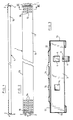
- an exemplary floor consisting of a metal profile 1 having a general U shape.
- the profile 1 is for example made of galvanized steel.
- the main face 11 of the profile has parallel bosses 12 serving as load distributors.
- non-slip reliefs 14 in any number.
- suspension hooks 2 intended to fit two horizontal crosspieces of a construction, for example a scaffolding, so as to suspend the floor 1.
- stiffeners are usefully provided inside the profile in order to ensure the desired stiffness combined with the desired lightness of the assembly. They each consist of a section welded between the ends of the lower wings of section 1.
- Figure 4 shows on an enlarged scale one end of the floor 1 and it shows in particular a hooking and locking device for fixing the floor on a horizontal crosspiece of a construction.
- the hooks 2 are welded to a support 3, consisting for example of a U-shaped iron, fixed at the end and inside the profile 1.
- the core of the iron 3, that is to say -to say the vertical member of the support is pierced with an opening 4 having its horizontal axis located in the same vertical plane as the longitudinal axis of one of the suspension hooks 2.
- In the opening 4 passes the upper part of a pivoting lock 6 hooked to the lower part of the support 3 so as to be able to pivot in a vertical plane.
- the lower end of the bolt 6 passes through an opening in the lower wing of the iron 3 and it is provided with a hooking head 7 constituted, for example, by a self-tapping screw with a cylindrical head.
- the attachment head 7 ensures the suspension of the lock 6 while allowing the pivoting thereof around a horizontal axis.
- a lock 6 is provided at each end of the floor 1 as shown in Figure 1. It is obvious that one could provide two locks at each end, although in practice a lock at each end is sufficient to ensure the security of the fixation.
- Unlocking a binding is also very simple.
- a pressure on the heel 62 of the latch 6 is sufficient to rotate the latter in the opposite direction to that of the movement of the needles of a watch and release it from the cross-member.
- the exemplary embodiment of the locking device according to the invention also has the advantage of allowing easy replacement of the lock 6.
- the latter is attached to the support 3 by a head formed by a screw 7, just unscrew the head 7 to remove the lock 6 and screw the head 7 into the new lock.
- the profile 1 and the latches 6 are produced in such a way that the lateral wings 15 and 16 of the profile (see fi gure 3) protect the latches 6 when they are in their raised position (unlocking position).
- the heel 62 of the latch 6 does not exceed the lower wing 17 of the profile when the latch is raised.
- the fact that the bolts 6 of a floor are thus retractable inside the profile 1 makes it possible to lay the floors on the ground, without risk of damaging them, and this facilitates the storage of the floors according to the invention.
- the main face 11 of the profile 1 has parallel bosses 12 ( Figures 1 and 2). These bosses 12 delimit between them channels 13 which facilitate the flow of rainwater, in particular through holes 18 located in the channels 13. In this way, rainwater does not stagnate on the surface of the floor and This prevents ice sheets from forming in freezing weather, which increases safety for site personnel.
Landscapes
- Engineering & Computer Science (AREA)
- Architecture (AREA)
- Mechanical Engineering (AREA)
- Civil Engineering (AREA)
- Structural Engineering (AREA)
- Mutual Connection Of Rods And Tubes (AREA)
- Ladders (AREA)
- Floor Finish (AREA)
- Clamps And Clips (AREA)
Priority Applications (3)
| Application Number | Priority Date | Filing Date | Title |
|---|---|---|---|
| EP89870109A EP0407680B1 (de) | 1989-07-12 | 1989-07-12 | Verfahren zum Verbinden einer vorgefertigten Gerüstbühne mit einer horizontalen Traverse, und vorgefertigte Gerüstbühne dazu |
| DE89870109T DE68913733D1 (de) | 1989-07-12 | 1989-07-12 | Verfahren zum Verbinden einer vorgefertigten Gerüstbühne mit einer horizontalen Traverse, und vorgefertigte Gerüstbühne dazu. |
| AT89870109T ATE102679T1 (de) | 1989-07-12 | 1989-07-12 | Verfahren zum verbinden einer vorgefertigten geruestbuehne mit einer horizontalen traverse, und vorgefertigte geruestbuehne dazu. |
Applications Claiming Priority (1)
| Application Number | Priority Date | Filing Date | Title |
|---|---|---|---|
| EP89870109A EP0407680B1 (de) | 1989-07-12 | 1989-07-12 | Verfahren zum Verbinden einer vorgefertigten Gerüstbühne mit einer horizontalen Traverse, und vorgefertigte Gerüstbühne dazu |
Publications (2)
| Publication Number | Publication Date |
|---|---|
| EP0407680A1 true EP0407680A1 (de) | 1991-01-16 |
| EP0407680B1 EP0407680B1 (de) | 1994-03-09 |
Family
ID=8203283
Family Applications (1)
| Application Number | Title | Priority Date | Filing Date |
|---|---|---|---|
| EP89870109A Expired - Lifetime EP0407680B1 (de) | 1989-07-12 | 1989-07-12 | Verfahren zum Verbinden einer vorgefertigten Gerüstbühne mit einer horizontalen Traverse, und vorgefertigte Gerüstbühne dazu |
Country Status (3)
| Country | Link |
|---|---|
| EP (1) | EP0407680B1 (de) |
| AT (1) | ATE102679T1 (de) |
| DE (1) | DE68913733D1 (de) |
Cited By (7)
| Publication number | Priority date | Publication date | Assignee | Title |
|---|---|---|---|---|
| FR2690188A1 (fr) * | 1992-04-17 | 1993-10-22 | Edac | Planche d'échafaudage métallique. |
| DE9314353U1 (de) * | 1993-09-22 | 1993-12-16 | Hans-J. Gebauer GmbH, 56727 Mayen | Arbeitsbühne, vorzugsweise Gerüst zur Einrüstung von Fassaden o.dgl. |
| FR2702507A1 (fr) * | 1993-03-08 | 1994-09-16 | Entreprose Montalev | Elément de plancher pour échafaudage. |
| EP0637660A1 (de) * | 1993-08-02 | 1995-02-08 | Gerald Merkel | Aushebesicherung für Gerüstbelagteile |
| GB2294495A (en) * | 1994-10-28 | 1996-05-01 | Alloy Die & Cast Ltd | Locking device for scaffolding platform |
| DE19633091A1 (de) * | 1996-08-16 | 1998-02-19 | Peri Gmbh | Zerlegbares Fassadengerüst, Bodenplatte für ein zerlegbares Fassadengerüst und Verfahren zum Demontieren und Montieren einer Bodenplatte eines zerlegbaren Fassadengerüstes |
| FR2781534A1 (fr) * | 1998-07-21 | 2000-01-28 | Entrepose Echafaudages | Dispositif de verrouillage sur une traverse horizontale |
Citations (5)
| Publication number | Priority date | Publication date | Assignee | Title |
|---|---|---|---|---|
| GB2058189A (en) * | 1979-08-15 | 1981-04-08 | Gkn Mills Building Serv | Releasable Fastenings |
| FR2485598A3 (fr) * | 1980-06-26 | 1981-12-31 | Fap Fabrica Attrezature Prefab | Plate-forme pour echafaudages tubulaires metalliques |
| GB2127086A (en) * | 1982-08-20 | 1984-04-04 | Alto Systems Ltd | Automatic latch for use in scaffolding structures |
| FR2573115A1 (fr) * | 1984-11-09 | 1986-05-16 | Layher Eberhard | Panneau de cadre d'echafaudage. |
| EP0305014A2 (de) * | 1987-08-28 | 1989-03-01 | Beleggingsmaatschappij Bouwmaterieel Europa B.V. | Gerüst mit Pfosten, Riegel und an diesen Riegeln befestigten Gerüstplatten |
-
1989
- 1989-07-12 EP EP89870109A patent/EP0407680B1/de not_active Expired - Lifetime
- 1989-07-12 AT AT89870109T patent/ATE102679T1/de not_active IP Right Cessation
- 1989-07-12 DE DE89870109T patent/DE68913733D1/de not_active Expired - Lifetime
Patent Citations (5)
| Publication number | Priority date | Publication date | Assignee | Title |
|---|---|---|---|---|
| GB2058189A (en) * | 1979-08-15 | 1981-04-08 | Gkn Mills Building Serv | Releasable Fastenings |
| FR2485598A3 (fr) * | 1980-06-26 | 1981-12-31 | Fap Fabrica Attrezature Prefab | Plate-forme pour echafaudages tubulaires metalliques |
| GB2127086A (en) * | 1982-08-20 | 1984-04-04 | Alto Systems Ltd | Automatic latch for use in scaffolding structures |
| FR2573115A1 (fr) * | 1984-11-09 | 1986-05-16 | Layher Eberhard | Panneau de cadre d'echafaudage. |
| EP0305014A2 (de) * | 1987-08-28 | 1989-03-01 | Beleggingsmaatschappij Bouwmaterieel Europa B.V. | Gerüst mit Pfosten, Riegel und an diesen Riegeln befestigten Gerüstplatten |
Cited By (8)
| Publication number | Priority date | Publication date | Assignee | Title |
|---|---|---|---|---|
| FR2690188A1 (fr) * | 1992-04-17 | 1993-10-22 | Edac | Planche d'échafaudage métallique. |
| FR2702507A1 (fr) * | 1993-03-08 | 1994-09-16 | Entreprose Montalev | Elément de plancher pour échafaudage. |
| EP0616098A1 (de) * | 1993-03-08 | 1994-09-21 | Entrepose-Montalev | Gerüstbodenelement |
| EP0637660A1 (de) * | 1993-08-02 | 1995-02-08 | Gerald Merkel | Aushebesicherung für Gerüstbelagteile |
| DE9314353U1 (de) * | 1993-09-22 | 1993-12-16 | Hans-J. Gebauer GmbH, 56727 Mayen | Arbeitsbühne, vorzugsweise Gerüst zur Einrüstung von Fassaden o.dgl. |
| GB2294495A (en) * | 1994-10-28 | 1996-05-01 | Alloy Die & Cast Ltd | Locking device for scaffolding platform |
| DE19633091A1 (de) * | 1996-08-16 | 1998-02-19 | Peri Gmbh | Zerlegbares Fassadengerüst, Bodenplatte für ein zerlegbares Fassadengerüst und Verfahren zum Demontieren und Montieren einer Bodenplatte eines zerlegbaren Fassadengerüstes |
| FR2781534A1 (fr) * | 1998-07-21 | 2000-01-28 | Entrepose Echafaudages | Dispositif de verrouillage sur une traverse horizontale |
Also Published As
| Publication number | Publication date |
|---|---|
| EP0407680B1 (de) | 1994-03-09 |
| ATE102679T1 (de) | 1994-03-15 |
| DE68913733D1 (de) | 1994-04-14 |
Similar Documents
| Publication | Publication Date | Title |
|---|---|---|
| CA1303810C (fr) | Structure de couverture decouvrable | |
| EP1525354B1 (de) | Gitter zum verschliessen einer rinne oder ähnlichem | |
| EP0099298B1 (de) | Befestigungsvorrichtung für ein Gebäude und Anwendung bei dem Aufbau von Gerüsten | |
| EP0407680B1 (de) | Verfahren zum Verbinden einer vorgefertigten Gerüstbühne mit einer horizontalen Traverse, und vorgefertigte Gerüstbühne dazu | |
| EP2543800B1 (de) | Verriegelungs- und Entriegelungsvorrichtung mindestens eines Abdeckelements auf einem Gestellrahmen dieses Elements | |
| FR2987856A1 (fr) | Attache en deux parties pour le support et la fixation d'une structure de travail en encorbellement a un mur | |
| FR3045086A1 (fr) | Garde-corps rabattable pour toit terrasse, batiment modulaire comprenant au moins un garde-corps rabattable et construction modulaire comprenant au moins deux batiments modulaires | |
| EP2363555B1 (de) | Verriegelungs- und Entriegelungsvorrichtung mit verbesserter Verschlusssicherheit | |
| FR2689546A1 (fr) | Dispositif pour le coffrage de plafond. | |
| EP1334236B1 (de) | Ausziehbare Barriere auf Rollen mit manuell auszieh- und einziehbaren Schwenkelementen | |
| EP1160382B1 (de) | Einstiegschacht mit angelenktem Deckel und Diebstahlsicherungsvorrichtung für eine Ausschachtung im Boden | |
| FR2589506A1 (fr) | Dispositif de fixation d'une console pour circulation ou coffrage sur une paroi verticale d'un ouvrage en beton | |
| EP1253280B1 (de) | Sicherheitsverankerungsvorrichtung | |
| FR2799478A1 (fr) | Dispositif de fermeture de regard de visite ou d'inspection | |
| WO2016092175A1 (fr) | Ensemble pour regard de chaussée comprenant un cadre, un couvercle et un kit permettant le montage articulé du couvercle au cadre | |
| EP0698692B1 (de) | Abdeckung, insbesondere für den Zugangsschacht zu einem Hydranten, und die sie bildenden Elemente | |
| FR2912171A1 (fr) | Fermeture securitaire pour rideaux de piscines | |
| FR2679289A1 (fr) | Dispositif anti-dechaussement pour vantail coulissant, notamment de porte, fenetre ou analogue. | |
| FR2899253A1 (fr) | Dispositif de securite pour l'acces a une chambre technique situee sous une chaussee ou analogue | |
| FR2480338A1 (fr) | Structure de protection pour couvreur et montant correspondant | |
| FR2929306A1 (fr) | Crochet a verrou integre pour element support de banche | |
| EP2365163B1 (de) | Treibstangenverschluss für Flügel | |
| FR2683245A1 (fr) | Plateforme en encorbellement amovible, notamment pour circulation ou coffrage dans les ouvrages en beton. | |
| FR3161437A1 (fr) | Attache rapide pour engins de travaux publics | |
| FR3161440A1 (fr) | Attache rapide pour engins de travaux publics |
Legal Events
| Date | Code | Title | Description |
|---|---|---|---|
| PUAI | Public reference made under article 153(3) epc to a published international application that has entered the european phase |
Free format text: ORIGINAL CODE: 0009012 |
|
| AK | Designated contracting states |
Kind code of ref document: A1 Designated state(s): AT BE CH DE ES FR GB GR IT LI LU NL SE |
|
| 17P | Request for examination filed |
Effective date: 19910628 |
|
| 17Q | First examination report despatched |
Effective date: 19911218 |
|
| GRAA | (expected) grant |
Free format text: ORIGINAL CODE: 0009210 |
|
| AK | Designated contracting states |
Kind code of ref document: B1 Designated state(s): AT BE CH DE ES FR GB GR IT LI LU NL SE |
|
| PG25 | Lapsed in a contracting state [announced via postgrant information from national office to epo] |
Ref country code: IT Free format text: LAPSE BECAUSE OF FAILURE TO SUBMIT A TRANSLATION OF THE DESCRIPTION OR TO PAY THE FEE WITHIN THE PRE;WARNING: LAPSES OF ITALIAN PATENTS WITH EFFECTIVE DATE BEFORE 2007 MAY HAVE OCCURRED AT ANY TIME BEFORE 2007. THE CORRECT EFFECTIVE DATE MAY BE DIFFERENT FROM THE ONE RECORDED.SCRIBED TIME-LIMIT Effective date: 19940309 Ref country code: ES Free format text: THE PATENT HAS BEEN ANNULLED BY A DECISION OF A NATIONAL AUTHORITY Effective date: 19940309 Ref country code: AT Effective date: 19940309 Ref country code: SE Free format text: THE PATENT HAS BEEN ANNULLED BY A DECISION OF A NATIONAL AUTHORITY Effective date: 19940309 Ref country code: NL Effective date: 19940309 Ref country code: GB Effective date: 19940309 Ref country code: GR Free format text: LAPSE BECAUSE OF FAILURE TO SUBMIT A TRANSLATION OF THE DESCRIPTION OR TO PAY THE FEE WITHIN THE PRESCRIBED TIME-LIMIT Effective date: 19940309 Ref country code: DE Effective date: 19940309 |
|
| REF | Corresponds to: |
Ref document number: 102679 Country of ref document: AT Date of ref document: 19940315 Kind code of ref document: T |
|
| REF | Corresponds to: |
Ref document number: 68913733 Country of ref document: DE Date of ref document: 19940414 |
|
| NLV1 | Nl: lapsed or annulled due to failure to fulfill the requirements of art. 29p and 29m of the patents act | ||
| GBV | Gb: ep patent (uk) treated as always having been void in accordance with gb section 77(7)/1977 [no translation filed] |
Effective date: 19940309 |
|
| PLBE | No opposition filed within time limit |
Free format text: ORIGINAL CODE: 0009261 |
|
| STAA | Information on the status of an ep patent application or granted ep patent |
Free format text: STATUS: NO OPPOSITION FILED WITHIN TIME LIMIT |
|
| 26N | No opposition filed | ||
| PGFP | Annual fee paid to national office [announced via postgrant information from national office to epo] |
Ref country code: CH Payment date: 19960712 Year of fee payment: 8 |
|
| PGFP | Annual fee paid to national office [announced via postgrant information from national office to epo] |
Ref country code: BE Payment date: 19970612 Year of fee payment: 9 |
|
| PGFP | Annual fee paid to national office [announced via postgrant information from national office to epo] |
Ref country code: FR Payment date: 19970730 Year of fee payment: 9 |
|
| PG25 | Lapsed in a contracting state [announced via postgrant information from national office to epo] |
Ref country code: CH Free format text: LAPSE BECAUSE OF NON-PAYMENT OF DUE FEES Effective date: 19970731 Ref country code: LI Free format text: LAPSE BECAUSE OF NON-PAYMENT OF DUE FEES Effective date: 19970731 |
|
| PGFP | Annual fee paid to national office [announced via postgrant information from national office to epo] |
Ref country code: LU Payment date: 19970804 Year of fee payment: 9 |
|
| REG | Reference to a national code |
Ref country code: CH Ref legal event code: PL |
|
| PG25 | Lapsed in a contracting state [announced via postgrant information from national office to epo] |
Ref country code: LU Free format text: LAPSE BECAUSE OF NON-PAYMENT OF DUE FEES Effective date: 19980712 |
|
| PG25 | Lapsed in a contracting state [announced via postgrant information from national office to epo] |
Ref country code: BE Free format text: LAPSE BECAUSE OF NON-PAYMENT OF DUE FEES Effective date: 19980731 |
|
| BERE | Be: lapsed |
Owner name: S.A. TRAVHYDRO ECHAFAUDAGES Effective date: 19980731 |
|
| PG25 | Lapsed in a contracting state [announced via postgrant information from national office to epo] |
Ref country code: FR Free format text: LAPSE BECAUSE OF NON-PAYMENT OF DUE FEES Effective date: 19990331 |
|
| REG | Reference to a national code |
Ref country code: FR Ref legal event code: ST |