EP0306618B1 - Entwicklungsgerät - Google Patents
Entwicklungsgerät Download PDFInfo
- Publication number
- EP0306618B1 EP0306618B1 EP88107899A EP88107899A EP0306618B1 EP 0306618 B1 EP0306618 B1 EP 0306618B1 EP 88107899 A EP88107899 A EP 88107899A EP 88107899 A EP88107899 A EP 88107899A EP 0306618 B1 EP0306618 B1 EP 0306618B1
- Authority
- EP
- European Patent Office
- Prior art keywords
- toner
- developing agent
- developing
- developing apparatus
- roller
- Prior art date
- Legal status (The legal status is an assumption and is not a legal conclusion. Google has not performed a legal analysis and makes no representation as to the accuracy of the status listed.)
- Expired - Lifetime
Links
Images
Classifications
-
- G—PHYSICS
- G03—PHOTOGRAPHY; CINEMATOGRAPHY; ANALOGOUS TECHNIQUES USING WAVES OTHER THAN OPTICAL WAVES; ELECTROGRAPHY; HOLOGRAPHY
- G03G—ELECTROGRAPHY; ELECTROPHOTOGRAPHY; MAGNETOGRAPHY
- G03G15/00—Apparatus for electrographic processes using a charge pattern
- G03G15/06—Apparatus for electrographic processes using a charge pattern for developing
- G03G15/08—Apparatus for electrographic processes using a charge pattern for developing using a solid developer, e.g. powder developer
-
- G—PHYSICS
- G03—PHOTOGRAPHY; CINEMATOGRAPHY; ANALOGOUS TECHNIQUES USING WAVES OTHER THAN OPTICAL WAVES; ELECTROGRAPHY; HOLOGRAPHY
- G03G—ELECTROGRAPHY; ELECTROPHOTOGRAPHY; MAGNETOGRAPHY
- G03G15/00—Apparatus for electrographic processes using a charge pattern
- G03G15/06—Apparatus for electrographic processes using a charge pattern for developing
- G03G15/08—Apparatus for electrographic processes using a charge pattern for developing using a solid developer, e.g. powder developer
- G03G15/0806—Apparatus for electrographic processes using a charge pattern for developing using a solid developer, e.g. powder developer on a donor element, e.g. belt, roller
- G03G15/0812—Apparatus for electrographic processes using a charge pattern for developing using a solid developer, e.g. powder developer on a donor element, e.g. belt, roller characterised by the developer regulating means, e.g. structure of doctor blade
-
- G—PHYSICS
- G03—PHOTOGRAPHY; CINEMATOGRAPHY; ANALOGOUS TECHNIQUES USING WAVES OTHER THAN OPTICAL WAVES; ELECTROGRAPHY; HOLOGRAPHY
- G03G—ELECTROGRAPHY; ELECTROPHOTOGRAPHY; MAGNETOGRAPHY
- G03G15/00—Apparatus for electrographic processes using a charge pattern
- G03G15/06—Apparatus for electrographic processes using a charge pattern for developing
- G03G15/08—Apparatus for electrographic processes using a charge pattern for developing using a solid developer, e.g. powder developer
- G03G15/0806—Apparatus for electrographic processes using a charge pattern for developing using a solid developer, e.g. powder developer on a donor element, e.g. belt, roller
- G03G15/0808—Apparatus for electrographic processes using a charge pattern for developing using a solid developer, e.g. powder developer on a donor element, e.g. belt, roller characterised by the developer supplying means, e.g. structure of developer supply roller
-
- G—PHYSICS
- G03—PHOTOGRAPHY; CINEMATOGRAPHY; ANALOGOUS TECHNIQUES USING WAVES OTHER THAN OPTICAL WAVES; ELECTROGRAPHY; HOLOGRAPHY
- G03G—ELECTROGRAPHY; ELECTROPHOTOGRAPHY; MAGNETOGRAPHY
- G03G2215/00—Apparatus for electrophotographic processes
- G03G2215/06—Developing structures, details
- G03G2215/0602—Developer
- G03G2215/0604—Developer solid type
- G03G2215/0614—Developer solid type one-component
-
- G—PHYSICS
- G03—PHOTOGRAPHY; CINEMATOGRAPHY; ANALOGOUS TECHNIQUES USING WAVES OTHER THAN OPTICAL WAVES; ELECTROGRAPHY; HOLOGRAPHY
- G03G—ELECTROGRAPHY; ELECTROPHOTOGRAPHY; MAGNETOGRAPHY
- G03G2215/00—Apparatus for electrophotographic processes
- G03G2215/06—Developing structures, details
- G03G2215/0634—Developing device
- G03G2215/0636—Specific type of dry developer device
Definitions
- This invention relates to a developing apparatus, and more particularly relates to improvements in and concerning a developing apparatus to be used in an electrophotographic system or an electrographic system for converting an electrostatic image formed on a photosensitive material or a dielectric material into a visible image with a one component developing agent formed solely of a non-magnetic toner.
- the developing apparatus of the type using a one component developing agent composed of a non-magnetic toner effects desired image development by applying the non-magnetic toner uniformly in the form of a thin layer on the surface of a rotating carrier roll and allowing the applied toner to be transferred onto an electrostatic image on a rotating sensitive drum disposed parallelly to and opposite the carrier roll across a fine gap in proportion to the charge lodged.
- the developing apparatus of the type using a one component developing agent composed of a non-magnetic toner has one serious problem that it is difficult to form a uniform thin layer of the toner stably on the surface of the carrier roll. This problem has impeded practical adoption of the developing apparatus.
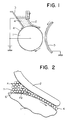
- the developing apparatus of this former invention accomplishes desired development of an electrostatic image by disposing a metal plate blade 2 in such a manner as to keep the rear side of the free end thereof, namely the flat surface on the downstream side thereof relative to the flow of a developing agent, in pressed contact with the peripheral surface of a carrier roll 1 having irregularities formed on a surface serving as a flexible developing agent carrier thereby enabling a non-magnetic toner 4 supplied as from a toner container 3 to be applied in the form of a thin layer of toner on the surface of the carrier roll 1 with the aid of the aforementioned metal plate blade 2 and opposing the thin layer of toner to a photosensitive drum 5 serving as an image carrier.
- the non-magnetic toner 4 in the toner container 3 is transferred along the carrier roll 1 to the interface between the metal plate blade 2 possessing elasticity and the carrier roll 1.
- the metal plate blade 2 has a large modulus of elasticity as compared with a rubber plate and meagerly lacks uniformity of the amount of deformation due to lack of uniformity of the pressure as of a fitting jig and exhibits minimal plastic deformation.
- the force with which the metal plate blade 2 is pressed against the carrier roll 1 is made uniform and the thin layer of toner, therefore, is formed in a uniform thickness.
- the metal plate blade 2 possesses electroconductivity, it can prevent the rear surface charging due to the triboelectricity possibly caused when the metal plate blade 2 is placed into pressed contact with the non-magnetic toner 4.
- the shear strength exerted on the aggregate of toner is constant at all times and the thin layer of toner can be formed in an uniform thickness.
- This formation of the thin layer of toner is effected, as illustrated in Fig. 2, by the repetition of the shear strength of the toner aggregate 7 under the exertion of the inhibiting force F1 generated by the metal plate blade 2 and the conveying force F2 generated by the carrier roll 1.
- the toner aggregate 7 stagnates between the carrier roll 1 and the metal plate blade 2 because slippage occurs between the toner aggregate 7 and the carrier roll 1.
- the subsequent toner cannot pass this position and the thin layer of toner is liable to sustain comby streaks thereon.
- the slippage between the toner aggregate 7 and the carrier roll 1 can be prevented to permit formation of an uniform thin layer of toner despite the toner's self-aggregating property by imparting irregularities 6 to the surface of the carrier roll 1.
- a method which comprises subjecting the surface to a treatment of sand blasting and/or a subsequent treatment of metal plating may be cited.
- the developing apparatus of the type using a one component developing agent composed solely of a non-magnetic toner it is extremely important that the irregularities should be formed on the surface of the carrier roll 1.
- the conventional method for the fabrication of the surface of the carrier roll 1 has not been sufficient for stable reproduction of images of satisfactory quality.
- the thin layer of toner is obtained in a thickness of about 60 to 120 ⁇ m, generally above 80 ⁇ m by keeping the metal plate blade 2 pressed strongly against the carrier roll 1.
- the images therefore, are reproduced in sufficient density.
- the application of such high pressure has entailed a problem that the pressure is transmitted also to the toner to give birth to frictional force and fogging of image.
- the pressure applied to the metal plate blade 2 is increased to decrease the thickness of the thin layer of toner, although the desired decrease of the layer thickness is indeed obtained, the toner is more liable to conglomeration and aggregation and the electric charge applied to the toner is apt to assume an unwanted opposite polarity.
- it is difficult to maintain the formation of an uniform thin layer of toner for a long period of time and to ensure stable reproduction of images of high quality.
- JP-57-14858 discloses a brush roller in contact with the surface of a developing agent carrier drum in order to remove toner and allow it to be redeposited. According to the present invention there is provided a developing apparatus as defined in Claim 1 below.
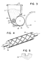
- the roller 29 As the toner stirrer an elastic roller 29 is used, the roller having a layer of polyurethane foam superposed concentrically on the peripheral surface of a shaft 27. Inside a developing agent container 22, this elastic roller 29 is revolved clockwise as kept in contact with the peripheral surface of a developing roller 24.
- helical grooves are inserted as shown in Fig. 4. In the present embodiment, the grooves have a width of 2 mm and a depth of 2 mm and a cross section of the shape shown in Fig. 5.
- grooves may be formed as inclined in one direction, they are desired to be formed as inclined in two directions as illustrated for the purpose of producing effective stirring of the toner and preventing possible deflection of the toner distribution within the developing agent container 22.
- a metal plate blade 25 and a sensitive drum 23 used in the present embodiment are identical with the corresponding components used in the embodiment of Fig. 3 of co-pending application 86302265.3 (the parent application, published as EP-A-196231).
- the part of the toner which has not participated in the development of an image has passed under the pressure of the elastic sheet member 26 for toner recovery, and has been returned to the interior of the developing agent container 22 comes into contact with the rotating elastic roller 29.
- part of the toner on the surface of the developing roller 24 is scraped off by a porous polyurethane foam 28 inside the developing agent container 22 and then forwarded in the direction of length of the roller along the helically intersecting grooves.
- the stirring effect produced as described above by the elastic roller 29 the electrostatic cohesion of toner particles is repressed and the formation of streaks in the peripheral direction of the roller is prevented.
- the peripheral surface of the elastic roller 29 is wrapped with a porous material such as polyurethane foam as illustrated in the present embodiment, since the toner is retained in the grooves of irregularities on the surface, the toner is readily supplied to the roller surface and the uniform toner layer is formed at all times even when the toner is supplied smoothly to the surface of the developing roller 24 and, as a result, the toner is amply consumed in the development of images of numerous line pairs. Further when helical grooves are formed in two intersecting directions on the surface of the elastic roller as illustrated, the possibility of the toner being unevenly distributed inside the developing agent container is nil.
- a developing roller was produced by subjecting the peripheral surface of an aluminum cylinder 24 mm in outside diameter to a polishing treatment, a sand blasting treatment to obtain surface roughness, and an electroless nickel plating treatment. To the developing roller, a DC bias voltage of +100 V was applied for the purpose of preventing the occurrence of image fogging.
- Elastic sheet member for foramtion of toner layer
- An elastic sheet member for the formation of a toner layer was made of a phosphor bronze sheet 0.2 mm in thickness.
- the pressure, P, applied to the roller was 100g/cm.
- Non-magnetic toner
- a toner consisting preponderantly of a polyester type substance and further incorporating therein a pigment such as carbon and other additives and having an averqage particle diameter of 12 ⁇ m was used.
- a photosensitive drum produced by forming a layer of selenium type photoconductive material on the peripheral surface of an aluminum cylinder and having an outer diameter of 80 mm was used.
- the peripheral speed of this sensitive drum was equal to that of the aforementioned developing roller.
- This sensitive drum was rotated counterclockwise, namely, in a direction opposite the direction of the rotation of the aforementioned roller.
- the maximum potential of the elctrostatic image formed on the surface of the sensitive drum was +800 V.
- the sensitive drum was disposed so that the distance of the surface of the sensitive drum to the surface of the roller would be 0.2 mm when the two members approached most to each other.
- An elastic roller consisted of a stainless steel shaft 8 mm in outside diameter and polyurethane foam coating 15 mm in outside diameter. The elastic roller was disposed so that a nipping width of 3 mm would occur between the elastic roller and the developing roller.
- the development was carried out by a method which comprised rotating the developing roller 24 at a peripheral speed of 130 mm/sec and the elastic roller at a peripheral speed of 30 mm/sec respectively both in the clockwise direction, forming a thin layer of toner about 25 ⁇ m in thickness on the surface of the developing drum 24, and allowing the toner which has been negatively charged by the frictional electrification with the elastic sheet member 25 for the formation of a toner layer to be transferred toward the sensitive drum 23 by the Coulomb force. Even after 10,000 cycles of the duplication mentioned above, the developed images showed no discernible lack of uniform density and the toner layer on the surface of the developing roller showed no sign of unevenness.
- the embodiment has been described as using an elastic roller as the toner stirrer.
- This invention does not require the toner stirrer to be limited to the elastic roller.
- a mesh plate possessing elasticity and wrapped around a developing roll as illustrated in Fig. 4 an elastic sheet formed of an elastic flat sheet possessing minute irregularities on the surface thereof may be used instead.
Landscapes
- Physics & Mathematics (AREA)
- General Physics & Mathematics (AREA)
- Dry Development In Electrophotography (AREA)
Claims (4)
- Entwicklungsgerät, umfassend: einen beweglichen Entwicklungsmittelträger (24), der geeignet ist, ein Einkomponenten-Entwicklungsmittel, welches aus einem nichtmagnetischen Toner (21) zusammengesetzt ist, zu tragen und zu bewegen, und dieses Entwicklungsmittel einem latenten elektrostatischen Bild zuzuführen und ein flexibles Beschichtungselement, welches aus einer elastischen Platte (25) gebildet wird, die gegen die Oberfläche des beweglichen Entwicklungsmittelträgers (24) gepreßt wird und an ihrem einen Ende in ihrer Lage gehaltert wird, wobei das Entwicklungsgerät desweiteren einen Entwicklungsmittelbehälter (22) umfaßt, in welchem ein Tonerumwälzelement (29) vorgesehen ist, dadurch gekennzeichnet, daß das flexible Beschichtungselement (25) so angeordnet ist, daß sein freies Ende zur Bewegungsrichtung des beweglichen Entwicklungsmittelträgers entgegengesetzt ausgerichtet ist, und daß das Tonerumwälzelement angrenzend an oder in gleitendem Kontakt mit dem Entwicklungsmittelträger (24) angeordnet und so ausgebildet ist, daß es den Toner auf der Oberfläche des Entwicklungsmittelträgers (24) gleichmäßig verteilt.
- Ein Entwicklungsgerät nach Anspruch 1, ferner dadurch gekennzeichnet, daß das Tonerumwälzelement (29) eine elastische Walze umfaßt, welche, während sie sich in Berührungskontakt mit der Oberfläche des Entwicklungsmittelträgers (24) befindet, drehbar ist.
- Ein Entwicklungsgerät nach Anspruch 1 oder 2, ferner dadurch gekennzeichnet, daß das Tonerumwälzelement (29) eine elastische Walze aus Polyurethanschaum umfasst.
- Ein Entwicklungsgerät nach Anspruch 1 oder 2, ferner dadurch gekennzeichnet, daß das Tonerumwälzelement (29) eine elastische Walze aus Polyurethanschaum umfaßt, und daß auf der Oberfläche dieser elastischen Walze schraubenlinienförmige Nuten vorgesehen sind.
Applications Claiming Priority (6)
| Application Number | Priority Date | Filing Date | Title |
|---|---|---|---|
| JP60928/85 | 1985-03-27 | ||
| JP60060928A JPH0646331B2 (ja) | 1985-03-27 | 1985-03-27 | 現像装置の製造方法 |
| JP61836/85 | 1985-03-28 | ||
| JP60061836A JPS61221769A (ja) | 1985-03-28 | 1985-03-28 | 現像装置 |
| JP60143504A JP2557826B2 (ja) | 1985-06-29 | 1985-06-29 | 現像装置 |
| JP143504/85 | 1985-06-29 |
Related Parent Applications (1)
| Application Number | Title | Priority Date | Filing Date |
|---|---|---|---|
| EP86302265.3 Division | 1986-03-26 |
Publications (2)
| Publication Number | Publication Date |
|---|---|
| EP0306618A1 EP0306618A1 (de) | 1989-03-15 |
| EP0306618B1 true EP0306618B1 (de) | 1993-01-07 |
Family
ID=27297335
Family Applications (2)
| Application Number | Title | Priority Date | Filing Date |
|---|---|---|---|
| EP86302265A Expired EP0196231B1 (de) | 1985-03-27 | 1986-03-26 | Entwicklungsgerät |
| EP88107899A Expired - Lifetime EP0306618B1 (de) | 1985-03-27 | 1986-03-26 | Entwicklungsgerät |
Family Applications Before (1)
| Application Number | Title | Priority Date | Filing Date |
|---|---|---|---|
| EP86302265A Expired EP0196231B1 (de) | 1985-03-27 | 1986-03-26 | Entwicklungsgerät |
Country Status (5)
| Country | Link |
|---|---|
| US (1) | US4866480A (de) |
| EP (2) | EP0196231B1 (de) |
| JP (1) | JPH0646331B2 (de) |
| KR (1) | KR900001047B1 (de) |
| DE (2) | DE3664169D1 (de) |
Families Citing this family (31)
| Publication number | Priority date | Publication date | Assignee | Title |
|---|---|---|---|---|
| JPS62278578A (ja) * | 1986-05-26 | 1987-12-03 | Toshiba Corp | 現像装置 |
| US5148639A (en) * | 1988-07-29 | 1992-09-22 | Canon Kabushiki Kaisha | Surface roughening method for organic electrophotographic photosensitive member |
| JP3014103B2 (ja) * | 1989-07-17 | 2000-02-28 | ミノルタ株式会社 | 現像装置 |
| US5674408A (en) * | 1990-03-24 | 1997-10-07 | Ricoh Company, Ltd. | Developer carrier capable of forming microfields thereon and method of producing the same |
| JP3057299B2 (ja) * | 1991-03-22 | 2000-06-26 | 株式会社リコー | 画像形成方法 |
| US5450176A (en) * | 1993-05-20 | 1995-09-12 | Mita Industrial Co., Ltd. | Developing device with rigid member toner limiting means |
| CA2160649C (en) * | 1994-10-17 | 1999-11-23 | Yoshiya Nomura | Toner container, toner container assembling method, process cartridge, and electrophotographic image forming apparatus |
| CA2213203A1 (en) | 1995-02-17 | 1996-08-22 | Sheldon Lee Roderick | Electroless plated magnetic brush roller for xerographic copiers, printers and the like |
| JP3200325B2 (ja) * | 1995-04-12 | 2001-08-20 | シャープ株式会社 | 現像装置 |
| US5819145A (en) * | 1995-07-31 | 1998-10-06 | Ricoh Company, Ltd. | Image forming device for forming a uniform toner layer on a developing roller |
| EP0856781B1 (de) * | 1997-01-31 | 2004-08-11 | Seiko Epson Corporation | Entwicklungseinheit |
| JPH11194618A (ja) * | 1997-11-10 | 1999-07-21 | Canon Inc | 画像形成装置 |
| JPH11219032A (ja) * | 1998-02-03 | 1999-08-10 | Sharp Corp | 現像装置 |
| US6702423B2 (en) | 1998-05-27 | 2004-03-09 | Canon Kabushiki Kaisha | Cleaning device for inkjet printing head, cleaning method for inkjet printing head, inkjet recording apparatus, and wiper |
| JP3588563B2 (ja) * | 1999-03-31 | 2004-11-10 | キヤノン株式会社 | 現像剤担持部材、それを用いた現像装置及び画像形成装置 |
| JP2001281985A (ja) * | 2000-03-30 | 2001-10-10 | Sharp Corp | 現像装置 |
| ATE396429T1 (de) * | 2000-04-10 | 2008-06-15 | Seiko Epson Corp | Bilderzeugungsgerät wobei eine ac-spannung an das entwicklerelement angelegt wird |
| US6341420B1 (en) | 2000-08-02 | 2002-01-29 | Static Control Components, Inc. | Method of manufacturing a developer roller |
| US6539193B1 (en) * | 2001-08-23 | 2003-03-25 | Toshiba Tec Kabushiki Kaisha | Developing apparatus and image forming apparatus for stably forming a developer layer on a developer device |
| US6725007B2 (en) * | 2001-10-01 | 2004-04-20 | Canon Kabushiki Kaisha | Developing assembly and image-forming apparatus |
| GB0308198D0 (en) | 2003-04-09 | 2003-05-14 | Chiron Srl | ADP-ribosylating bacterial toxin |
| US7013104B2 (en) | 2004-03-12 | 2006-03-14 | Lexmark International, Inc. | Toner regulating system having toner regulating member with metallic coating on flexible substrate |
| US7236729B2 (en) | 2004-07-27 | 2007-06-26 | Lexmark International, Inc. | Electrophotographic toner regulating member with induced strain outside elastic response region |
| JP5067846B2 (ja) * | 2007-07-18 | 2012-11-07 | 株式会社リコー | 現像装置、プロセスカートリッジおよび画像形成装置 |
| EP2093629A3 (de) * | 2008-02-20 | 2010-03-10 | Seiko Epson Corporation | Entwicklungswalze, Entwicklungsvorrichtung und Bilderzeugungsvorrichtung |
| EP2093628A2 (de) * | 2008-02-20 | 2009-08-26 | Seiko Epson Corporation | Entwicklungswalze, Entwicklungsvorrichtung und Bilderzeugungsvorrichtung |
| JP2009265360A (ja) * | 2008-04-25 | 2009-11-12 | Konica Minolta Business Technologies Inc | 現像装置および画像形成装置 |
| US9158228B2 (en) * | 2011-09-16 | 2015-10-13 | Ricoh Company, Ltd. | Development device and image forming apparatus incorporating same |
| JP2013137500A (ja) * | 2011-11-28 | 2013-07-11 | Ricoh Co Ltd | 現像装置及び画像形成装置 |
| JP2013200551A (ja) * | 2012-02-22 | 2013-10-03 | Ricoh Co Ltd | 現像装置、画像形成装置及びプロセスカートリッジ |
| CN219831640U (zh) * | 2023-05-24 | 2023-10-13 | 中山市奔码打印耗材有限公司 | 非接触式刮片结构 |
Family Cites Families (36)
| Publication number | Priority date | Publication date | Assignee | Title |
|---|---|---|---|---|
| US2518645A (en) * | 1947-09-04 | 1950-08-15 | Richard J Shanahan | Journal lubricator |
| US3572288A (en) * | 1968-08-07 | 1971-03-23 | Xerox Corp | Development apparatus |
| US3651758A (en) * | 1969-12-17 | 1972-03-28 | Moore Business Forms Inc | Ink transfer system |
| US3863603A (en) * | 1974-01-07 | 1975-02-04 | Ibm | Magnetic brush roll having resilient polymeric surface |
| US3974554A (en) * | 1975-05-16 | 1976-08-17 | Xerox Corporation | Quadrangular trihelicoid gravure roll |
| US4100884A (en) * | 1976-02-25 | 1978-07-18 | Ricoh Company, Ltd. | Rubber developer roller using single component toner |
| US4136637A (en) * | 1977-03-09 | 1979-01-30 | Xerox Corporation | Continuous contrast development system |
| JPS5451846A (en) * | 1977-09-30 | 1979-04-24 | Ricoh Co Ltd | Electrostatic latent image developing device |
| JPS5492747A (en) * | 1977-12-29 | 1979-07-23 | Minolta Camera Co Ltd | Pressure fixing device of powder lmages |
| US4217769A (en) * | 1978-10-10 | 1980-08-19 | Consolidated Papers, Inc. | Method of forming a coating application roll |
| US4377332A (en) * | 1979-04-20 | 1983-03-22 | Canon Kabushiki Kaisha | Developing device |
| JPS5614260A (en) * | 1979-07-16 | 1981-02-12 | Canon Inc | Developing device |
| US4325627A (en) * | 1979-12-19 | 1982-04-20 | Savin Corporation | Method and apparatus for liquid-developing latent electrostatic images |
| DE3107055A1 (de) * | 1980-03-04 | 1982-01-07 | Canon K.K., Tokyo | "entwicklungsvorrichtung" |
| US4410259A (en) * | 1980-03-08 | 1983-10-18 | Mita Industrial Co., Ltd. | Apparatus for developing latent electrostatic image |
| JPS5764764A (en) * | 1980-10-09 | 1982-04-20 | Canon Inc | Dry type development device |
| JPS5766455A (en) * | 1980-10-11 | 1982-04-22 | Canon Inc | Development device |
| JPS5786869A (en) * | 1980-11-20 | 1982-05-31 | Canon Inc | Developing device |
| US4380966A (en) * | 1980-10-11 | 1983-04-26 | Canon Kabushiki Kaisha | Development apparatus |
| JPS57165866A (en) * | 1981-04-07 | 1982-10-13 | Toshiba Corp | Developing device |
| US4459009A (en) * | 1981-07-27 | 1984-07-10 | Xerox Corporation | Apparatus, process for charging toner particles |
| JPS58153973A (ja) * | 1982-03-10 | 1983-09-13 | Toshiba Corp | 現像装置 |
| JPS58216278A (ja) * | 1982-06-11 | 1983-12-15 | Olympus Optical Co Ltd | 画像形成装置 |
| US4419959A (en) * | 1982-09-29 | 1983-12-13 | Am International, Inc. | Magnetic toner retainer means |
| GB2128109B (en) * | 1982-10-15 | 1986-10-29 | Ricoh Kk | Development of electrostatic images |
| JPS5994352U (ja) * | 1982-12-14 | 1984-06-27 | 株式会社リコー | 現像装置 |
| JPS6033578A (ja) * | 1983-08-04 | 1985-02-20 | Toshiba Corp | 現像装置 |
| JPS6051853A (ja) * | 1983-08-31 | 1985-03-23 | Toshiba Corp | 現像装置 |
| JPS6051844A (ja) * | 1983-08-31 | 1985-03-23 | Toshiba Corp | 現像装置 |
| EP0138458B2 (de) * | 1983-09-30 | 1992-04-29 | Kabushiki Kaisha Toshiba | Entwicklungsgerät |
| US4558943A (en) * | 1983-11-07 | 1985-12-17 | Xerox Corporation | Developer roller |
| JPS60113273A (ja) * | 1983-11-24 | 1985-06-19 | Ricoh Co Ltd | 現像剤層厚制御装置 |
| JPS60229070A (ja) * | 1984-04-27 | 1985-11-14 | Toshiba Corp | 現像装置 |
| US4696255A (en) * | 1984-08-07 | 1987-09-29 | Ricoh Company, Ltd. | Developing apparatus |
| GB2163371B (en) * | 1984-08-07 | 1988-04-07 | Ricoh Kk | Developing electrostatic latent images |
| JPS61190361A (ja) * | 1985-02-20 | 1986-08-25 | Toshiba Corp | 現像装置 |
-
1985
- 1985-03-27 JP JP60060928A patent/JPH0646331B2/ja not_active Expired - Lifetime
-
1986
- 1986-03-18 KR KR1019860002004A patent/KR900001047B1/ko not_active Expired
- 1986-03-26 US US06/844,373 patent/US4866480A/en not_active Expired - Lifetime
- 1986-03-26 EP EP86302265A patent/EP0196231B1/de not_active Expired
- 1986-03-26 DE DE8686302265T patent/DE3664169D1/de not_active Expired
- 1986-03-26 DE DE8888107899T patent/DE3687461T2/de not_active Expired - Lifetime
- 1986-03-26 EP EP88107899A patent/EP0306618B1/de not_active Expired - Lifetime
Also Published As
| Publication number | Publication date |
|---|---|
| DE3687461D1 (de) | 1993-02-18 |
| US4866480A (en) | 1989-09-12 |
| JPH0646331B2 (ja) | 1994-06-15 |
| KR860007568A (ko) | 1986-10-15 |
| EP0196231A2 (de) | 1986-10-01 |
| KR900001047B1 (ko) | 1990-02-26 |
| EP0196231B1 (de) | 1989-06-28 |
| DE3687461T2 (de) | 1993-04-29 |
| EP0196231A3 (en) | 1987-01-14 |
| DE3664169D1 (en) | 1989-08-03 |
| EP0306618A1 (de) | 1989-03-15 |
| JPS61219974A (ja) | 1986-09-30 |
Similar Documents
| Publication | Publication Date | Title |
|---|---|---|
| EP0306618A1 (de) | Entwicklungsgerät | |
| US4100884A (en) | Rubber developer roller using single component toner | |
| JP2843660B2 (ja) | 現像装置 | |
| US5311264A (en) | Developing apparatus for developing electrostatic latent image using one component developer | |
| US5495322A (en) | Electrophotographic developing apparatus which utilizes single-component developing material | |
| JPS59116769A (ja) | 現像装置 | |
| JP3038934B2 (ja) | 現像装置 | |
| JPH09311539A (ja) | 現像装置 | |
| EP0636950B1 (de) | Entwicklungsgerät mit einer sich drehenden Entwicklerzufuhreinheit einer Entwicklerträgereinheit | |
| JPS6337380B2 (de) | ||
| JPH0384570A (ja) | 現像装置 | |
| US5666620A (en) | Developing device for peeling toner using peeling rotary member | |
| JP2843651B2 (ja) | 現像装置 | |
| JP2990622B2 (ja) | 非磁性一成分現像装置 | |
| JPH0651618A (ja) | 現像装置 | |
| JP2725076B2 (ja) | 現像装置 | |
| JP3042908B2 (ja) | 現像装置 | |
| JP3112539B2 (ja) | 現像装置 | |
| JP3078348B2 (ja) | 現像方法及びその装置 | |
| JP2557826B2 (ja) | 現像装置 | |
| JP3020641B2 (ja) | 現像装置 | |
| JP3058714B2 (ja) | 現像装置 | |
| JPS60103370A (ja) | 電子複写機の現像装置 | |
| JP3078337B2 (ja) | 現像方法及びその装置 | |
| JPH0844209A (ja) | 現像装置 |
Legal Events
| Date | Code | Title | Description |
|---|---|---|---|
| PUAI | Public reference made under article 153(3) epc to a published international application that has entered the european phase |
Free format text: ORIGINAL CODE: 0009012 |
|
| 17P | Request for examination filed |
Effective date: 19880603 |
|
| AC | Divisional application: reference to earlier application |
Ref document number: 196231 Country of ref document: EP |
|
| AK | Designated contracting states |
Kind code of ref document: A1 Designated state(s): DE FR GB NL |
|
| 17Q | First examination report despatched |
Effective date: 19910802 |
|
| GRAA | (expected) grant |
Free format text: ORIGINAL CODE: 0009210 |
|
| AC | Divisional application: reference to earlier application |
Ref document number: 196231 Country of ref document: EP |
|
| AK | Designated contracting states |
Kind code of ref document: B1 Designated state(s): DE FR GB NL |
|
| PG25 | Lapsed in a contracting state [announced via postgrant information from national office to epo] |
Ref country code: NL Effective date: 19930107 |
|
| REF | Corresponds to: |
Ref document number: 3687461 Country of ref document: DE Date of ref document: 19930218 |
|
| ET | Fr: translation filed | ||
| NLV1 | Nl: lapsed or annulled due to failure to fulfill the requirements of art. 29p and 29m of the patents act | ||
| PLBE | No opposition filed within time limit |
Free format text: ORIGINAL CODE: 0009261 |
|
| STAA | Information on the status of an ep patent application or granted ep patent |
Free format text: STATUS: NO OPPOSITION FILED WITHIN TIME LIMIT |
|
| 26N | No opposition filed | ||
| REG | Reference to a national code |
Ref country code: GB Ref legal event code: 746 Effective date: 19981008 |
|
| REG | Reference to a national code |
Ref country code: FR Ref legal event code: D6 |
|
| REG | Reference to a national code |
Ref country code: GB Ref legal event code: IF02 |
|
| REG | Reference to a national code |
Ref country code: GB Ref legal event code: 732E |
|
| REG | Reference to a national code |
Ref country code: FR Ref legal event code: TQ |
|
| PGFP | Annual fee paid to national office [announced via postgrant information from national office to epo] |
Ref country code: FR Payment date: 20050308 Year of fee payment: 20 |
|
| PGFP | Annual fee paid to national office [announced via postgrant information from national office to epo] |
Ref country code: GB Payment date: 20050323 Year of fee payment: 20 |
|
| PGFP | Annual fee paid to national office [announced via postgrant information from national office to epo] |
Ref country code: DE Payment date: 20050324 Year of fee payment: 20 |
|
| PG25 | Lapsed in a contracting state [announced via postgrant information from national office to epo] |
Ref country code: GB Free format text: LAPSE BECAUSE OF EXPIRATION OF PROTECTION Effective date: 20060325 |
|
| REG | Reference to a national code |
Ref country code: GB Ref legal event code: PE20 |