EP0309265A2 - Bearbeitungsgerät für Dokumente - Google Patents
Bearbeitungsgerät für Dokumente Download PDFInfo
- Publication number
- EP0309265A2 EP0309265A2 EP88308846A EP88308846A EP0309265A2 EP 0309265 A2 EP0309265 A2 EP 0309265A2 EP 88308846 A EP88308846 A EP 88308846A EP 88308846 A EP88308846 A EP 88308846A EP 0309265 A2 EP0309265 A2 EP 0309265A2
- Authority
- EP
- European Patent Office
- Prior art keywords
- document
- platen
- reception
- printer head
- printer
- Prior art date
- Legal status (The legal status is an assumption and is not a legal conclusion. Google has not performed a legal analysis and makes no representation as to the accuracy of the status listed.)
- Withdrawn
Links
Images

Classifications
-
- G—PHYSICS
- G06—COMPUTING OR CALCULATING; COUNTING
- G06K—GRAPHICAL DATA READING; PRESENTATION OF DATA; RECORD CARRIERS; HANDLING RECORD CARRIERS
- G06K15/00—Arrangements for producing a permanent visual presentation of the output data, e.g. computer output printers
- G06K15/02—Arrangements for producing a permanent visual presentation of the output data, e.g. computer output printers using printers
- G06K15/16—Means for paper feeding or form feeding
-
- B—PERFORMING OPERATIONS; TRANSPORTING
- B41—PRINTING; LINING MACHINES; TYPEWRITERS; STAMPS
- B41J—TYPEWRITERS; SELECTIVE PRINTING MECHANISMS, i.e. MECHANISMS PRINTING OTHERWISE THAN FROM A FORME; CORRECTION OF TYPOGRAPHICAL ERRORS
- B41J11/00—Devices or arrangements of selective printing mechanisms, e.g. ink-jet printers or thermal printers, for supporting or handling copy material in sheet or web form
- B41J11/20—Platen adjustments for varying the strength of impression, for a varying number of papers, for wear or for alignment, or for print gap adjustment
-
- G—PHYSICS
- G07—CHECKING-DEVICES
- G07G—REGISTERING THE RECEIPT OF CASH, VALUABLES, OR TOKENS
- G07G5/00—Receipt-giving machines
Definitions
- This invention concerns document handling apparatus particularly such apparatus including a dot matrix printer for recording information on paper forms or slips which for any given form or slip comprises one or more sheets of paper.
- Conventional document handling apparatus including dot-matrix printers commonly comprise a single or multiple head dot-matrix printer contained in a housing having an opening allowing the insertion of a sheet of material such that it can be placed in proximity to the printer head which will then print any desired information on the sheet.
- Such printers are usually intended to print information on forms or slips of paper inserted into the printer housing. It is important for the paper sheets to be positioned correctly with respect to the printer head particularly in terms of the distance from the head. If the paper sheet was to be too close to the head of the printer the printed information may be illegible and if the paper sheet was too far away the individual pins of the dot matrix printer could penetrate its ribbon thus damaging it and/or break or otherwise damage the pins themselves.
- a problem with this arrangement occurs when the paper sheet on which the printer is to print the information is a form or slip composed of several sheets of paper and which may also include one or more sheets of carbon paper.
- the paper when placed on the bar or plate provided would be either to close to the printer head to permit legible printing or could be too thick to be placed between the bar and the head.
- the bar or plate such that it can be raised or lowered with respect to the printer head by adjustment of fixing screws or other similar means. Precise adjustment of a printer having such a configuration can be difficult and once the bar or plate is set to print on a form having, say, three sheets it would have to be adjusted again to print on a single sheet. During all such adjustments of the bar or plate it will be appreciated that the machine is unusable and hence if many adjustments are required the overall printing rate will be reduced.
- the present invention provides document handling apparatus comprising a document reception platen movable with respect to a printer head such that a document placed on the platen can be brought into register with the printer head, means attached to the reception platen operative to raise and lower the platen respectively towards and away from the printer head, spacing means disposed close to the printer head such as to contact one face of a document placed on the reception platen and prevent it being moved closer to the printer head, the relative position of the spacing means and the the printer head being such that a document in contact with the spacing means is at a distance from the printing head predetermined so as to allow the printer head during its operation to contact the document's surface, the apparatus also including means operative to move a document onto the reception platen, sensor means to sense the presence of a document on the reception platen and further respective means operative to move a document off the reception platen.
- the means attached to the reception platen include a solenoid having a movable core with one exposed end to which is attached a cam linkage pivotally connected to a cam lever which is in turn connected in an axially off-set manner to a substantially cylindrical cam, the cam being in contact with the reception platen's underside at one end of said platen, the other end of the platen being pivotally mounted so as to permit raising and lowering of the platen's free end by partial rotation of the cam.
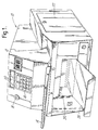
- a first preferred embodiment of document handling apparatus is indicated generally by the reference numeral 10 and includes a housing 12 commonly of sheet metal or plastics.
- the housing includes a document reception chute 14, a numeric key pad 16, a key operated on/off switch 18 and a display panel 20 for example a liquid crystal display.
- a lockable side panel 22 permits access to the housing's interior to those persons in possession of a key to open said panel 22.
- the casing also includes a document exit port 24 and a returned document catch tray 26.
- the document reception chute 14 leads to a dot-matrix printer unit 28 including a printer head 30 disposed within the housing 12 at an angle to a horizontal surface.
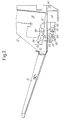
- a movable reception platen 32 is provided below the printer head 30, to a spindle 34 disposed at one end remote from the printer head 30, so that the reception platen 32 is movable about the spindle 34.
- the movement of the platen 32 in an upward direction is limited by spacing means comprising a shaft 36 on which is mounted one or more cylindrical stoppers 38, 39 preferably of rubber.
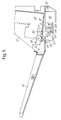
- the shaft 36 is positioned such that when the platen 32 is raised so as to contact the stoppers 38, 39 the platen 32 is positioned substantially parallel to the printer unit 28 ( See Fig. 4).
- the platen 32 is then disposed in relationship to the printer head 30 such that the distance between the platen 32 and the printer head 30 is substantially equal to the optimum distance for printing of letters or symbols by the printer head 30 onto a document (not shown) placed on the platen 32. This distance will depend on the precise type of printer head 32 being used.
- the platen 32 is provided with two rollers 50, 52 rotatable about a shaft 54 which is attached to the platen's underside by two brackets 56, 58. Slots are provided in the platen 32 such that the rollers 50, 52 partially project therethrough and a portion of each roller stands proud of the platen's upper surface. Furthermore the rollers 50, 52 are each disposed such that when the platen 32 is in the raised position that the portion of each roller 50, 52 projecting through the platen 32 contacts the stoppers 38, 39 provided on the shaft 36.
- rollers 50, 52 and stoppers 38, 39 thus co-operate to ensure correct positioning of the platen 32 with respect to the print head 30 whilst the rollers 50, 52 serve, when the platen 32 is lowered to facilitate movement of a document (not shown) placed in the reception chute 14 over the platen 32.
- the raising of the platen 32 to the printer head 30 is accomplished by a substantially cylindrical cam 40 eccentricallly mounted on cam lever 42 which is hingedly connected to a cam linkage 44.
- the cam linkage 44 is pivotally connected to a movable core 46 of a solenoid 48 provided with a return spring (not shown).
- a pin 49 provided on the cam lever 42 engages with the cam linkage 44 to limit the cylindrical cam's movement.
- the housing 12 also includes other components which are conventional in appearance and are not illustrated for simplicity. These components include a plurality of driven conveyor rollers operative to grip and move a document from a lowered platen 32 into a document guide path which leads to a rotary microfilm camera. Further conveyor rollers or similar means return the document to a document exit port 24 and returned document catch tray 26. Sensor means are also included disposed over the platen 32 and operative to sense the presence of a document placed thereon.
- a document (not shown) which may consist of one or more sheets of paper or a similar material is placed in the reception chute 14 where it slides down towards the printer unit 28 under the influence of gravity.
- Drive rollers (not shown) or other similar means are disposed betweeen the reception chute 14 and the printer unit 28 and are operative to grip said document and feed it over the rollers 50, 52 and onto the platen 32.
- the presence of a document on the platen 32 is sensed by the sensor which generates a control signal for the solenoid 48.
- the control signal causes the energisation of the solenoid 48 and hence the displacement of the moveable core 46 against the action of the return spring causing the rotation of the cam 40 via the cam lever 42 and the cam linkage 44.
- a control signal is generated causing a command or information request to appear on the liquid crystal display 20.
- the operator then inputs the information which is to be printed onto the document using the numeric keypad 16.
- the information thus entered is first displayed on the liquid crystal display 20 for checking and is then printed by the printer head 30 onto the document's upper surface. If it is desired the printer 28 may be pre-programmed to print the inputted information in pre-determined positions on the document as well as additional information or data which has been pre-programmed into the printer 28.
- the solenoid 48 is deactivated.
- the return spring causes the core 46 to return to its rest position rotating the cam 40 and lowering the platen 32 and releasing the document.
- the printer head 30 will always be the same distance from the document regardless of the number of sheets of paper of which it is composed. Thus the information printed will always be legible and there will be little risk of damage to the printer head 30 due to incorrectly positioned paper.
- the document Once the document has been released by the lowered platen 32 it is moved off the platen 32 by further rollers (not shown) and over the platen pivot spindle 34. The document is then fed to a microfilming unit (not shown) including for example a rotary mocrofilm camera. The document, including the information entered thereon by the printer, is photographically reproduced on microfilm which reproduction is then stored within the housing 12. The original document is then returned to the operator via the document exit port 24 and the returned document catch tray 26.
- a microfilming unit including for example a rotary mocrofilm camera
- microfilmed documents may be accessed by removing side panel 22 which require a corresponding key.
- a further key is then required to remove the microfilm from the microfilming unit.
- the use of such lockable panels ensures that the microfilmed documents are only available to authorised personnel.
- a further security measure is to restrict the use of the machine 10 by providing the key operated on/off switch thus making it impossible to operate without a corresponding key. It will also be appreciated that neither the printer 28 or the microfilming unit may be operated separately and that any document placed in the reception chute 14 whilst the machine 10 is in operation will be reproduced onto microfilm.
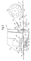
- Fig. 5 illustrates a second embodiment of document handling apparatus according to the invention which is referred to generally by the reference numeral 60. Parts which are identical to those already described are referred to by the same reference numerals.
- a housing 12 is provided with a document chute 14 leading to a movable platen 32 located below a dot matrix printer 28 having a printer head 30.
- the housing 12 is also provided with a numeric keypad 16 and display 20.
- the platen 32 is raised and lowered with respect to the head 30 by a cam 40 eccentrically connected to a cam lever 42 hinged to a cam linkage 44.
- the cam linkage is attached to a movable core 46 of a solenoid 48 which is provided with a return spring (not shown).
- the platen 32 is pivotally journalled at one end thereof on a spindle 34.
- a document path 64 is provided extending from the platen 32 over an optical reading device 66 and thence between a pair of rollers 68, 70 one upper roller 68 of which is freely rotatable and the lower roller 70 being provided with means to cause its rotation for example a mechanical linkage to a motor (not shown) or similar.
- the document path 64 extends to a document exit 72 disposed opposite to the chute 14.
- a paper dispensing spool 74 Disposed over the document path 64 is a paper dispensing spool 74 around which is wound a length of paper tape 76. This tape 76 is led from the spool 74 over a tape guide 78 and between a second pair of rollers 80, 82 operative, when rotated, to feed the tape 76 onto the platen 32.
- a document for example a card is placed in the reception chute 14 and caused to move over the platen 32 by rollers 62 and thence onto the document platen 64.
- the document is pre-provided with data which is capable of being read by the optical reader 66.
- the data thus read is compared with pre-programmed data and an 'accept' or 'reject' decision is made.
- Such a decision will be carried out by a suitably programmed microprocessor (not shown) which has full working control of all the elements of the document handling apparatus. If the decision is to 'reject' then the document is caused to move further along the document path 64 until it leaves the housing 12 via the document exit 72.
- the printing head 30 is caused to print information on the document either as inputted by the keypad 16 or pre-programmed or a combination of these two.
- the printer 28 prints a bar code on the document as part of the printed information.
- This bar code identifies the specific document and can contain information relating to the data read by the optical reader 66.
- the document should be resubmitted to the apparatus 60 after a period of time has elapsed.
- the document enters the document chute 14 and is placed on the reception platen which is raised to the printer 28.
- a bar code reader 86 which is located alongside the printer head 30 scans the printed bar code and compares the information with stored values. The results of this comparison causes further pre-programmed information to be printed onto the document which is then returned to the apparatus operator.
- a further aspect of the apparatus 60 is that a bar code can be produced without requiring the insertion of a document into the housing.
- the paper spool 74 can be caused to dispense a length of paper 76 onto the platen 32.
- the bar code and any other desired information is then printed onto the paper by the printer 28 and the paper is then ejected from the housing 12, after severing means (not shown) cuts the length dispensed from the spool, via the document chute 14.
- the bar code thus produced may be read by the bar code reader 86 at a later date as with that printed on an original document.
- the solenoid means could be replaced by other mechanisms, for example pneumatic or hydraulic systems.
- the linkages between the solenoid core and the platen could be reduced in number or added to according to physical constraints imposed and the space available.
- the number of the rollers operative to move the document through the system can be increased or reduced as necessary.
- the upper free roller is preferably moveable in a vertical direction with respect to the lower drive roller.
Landscapes
- Physics & Mathematics (AREA)
- General Physics & Mathematics (AREA)
- Engineering & Computer Science (AREA)
- General Engineering & Computer Science (AREA)
- Theoretical Computer Science (AREA)
- Handling Of Sheets (AREA)
- Common Mechanisms (AREA)
- Handling Of Cut Paper (AREA)
- Sheets, Magazines, And Separation Thereof (AREA)
- Delivering By Means Of Belts And Rollers (AREA)
Applications Claiming Priority (2)
| Application Number | Priority Date | Filing Date | Title |
|---|---|---|---|
| GB8722622 | 1987-09-25 | ||
| GB878722622A GB8722622D0 (en) | 1987-09-25 | 1987-09-25 | Dot-matrix printers |
Publications (2)
| Publication Number | Publication Date |
|---|---|
| EP0309265A2 true EP0309265A2 (de) | 1989-03-29 |
| EP0309265A3 EP0309265A3 (de) | 1990-06-13 |
Family
ID=10624388
Family Applications (1)
| Application Number | Title | Priority Date | Filing Date |
|---|---|---|---|
| EP88308846A Withdrawn EP0309265A3 (de) | 1987-09-25 | 1988-09-23 | Bearbeitungsgerät für Dokumente |
Country Status (5)
| Country | Link |
|---|---|
| US (1) | US5000591A (de) |
| EP (1) | EP0309265A3 (de) |
| AU (1) | AU613959B2 (de) |
| GB (1) | GB8722622D0 (de) |
| NO (1) | NO884248L (de) |
Cited By (4)
| Publication number | Priority date | Publication date | Assignee | Title |
|---|---|---|---|---|
| GB2229677A (en) * | 1989-03-10 | 1990-10-03 | Hitachi Ltd | Registry of selectively printed data with respect to code-marked documents |
| GB2249997A (en) * | 1990-11-22 | 1992-05-27 | Alcatel Business Systems | Controlling selective printer formats in dependence on code-marks read from the print substrate |
| EP0396051A3 (de) * | 1989-05-01 | 1992-11-19 | Star Micronics Co., Ltd. | Drucker für strichkodiertes Papier |
| EP0780816A3 (de) * | 1995-12-22 | 2003-06-25 | Ncr International Inc. | Vorrichtung zum Erfassen der Anwesenheit und Geschwindigkeit eines Aufzeichnungsmediums |
Families Citing this family (19)
| Publication number | Priority date | Publication date | Assignee | Title |
|---|---|---|---|---|
| US5046005A (en) * | 1989-05-15 | 1991-09-03 | Versatile Suppliers, Inc. | Test scoring machine |
| JPH0473175A (ja) * | 1990-07-13 | 1992-03-09 | Tokyo Electric Co Ltd | プリンタ |
| JPH0471877A (ja) * | 1990-07-13 | 1992-03-06 | Tokyo Electric Co Ltd | 転写式プリンタ |
| US5324124A (en) * | 1993-01-28 | 1994-06-28 | International Business Machines Corporation | Guide system for feed roll entry |
| US5366301A (en) * | 1993-12-14 | 1994-11-22 | Hewlett-Packard Company | Record media gap adjustment system for use in printers |
| US5672015A (en) * | 1994-04-11 | 1997-09-30 | International Business Machines Corporation | Apparatus and method for printing |
| US5683187A (en) * | 1996-06-18 | 1997-11-04 | Scitex Digital Printing, Inc. | Digital color press platen assembly with pivoting platen frame |
| JPH10250181A (ja) * | 1997-01-13 | 1998-09-22 | Canon Inc | 画像記録装置 |
| US5797687A (en) * | 1997-03-11 | 1998-08-25 | Hewlett-Packard Company | Paper stacker activation for printer input/output |
| US20060165606A1 (en) * | 1997-09-29 | 2006-07-27 | Nektar Therapeutics | Pulmonary delivery particles comprising water insoluble or crystalline active agents |
| JP3022849B2 (ja) * | 1998-01-05 | 2000-03-21 | セイコーエプソン株式会社 | プリンタ |
| US6113289A (en) * | 1998-01-05 | 2000-09-05 | Seiko Epson Corporation | Dot recording device |
| US6344904B1 (en) * | 1998-10-03 | 2002-02-05 | John E. Mercer | Arrangement for reading from and/or writing to flexible sheet media in a curved configuration and method |
| US7871598B1 (en) | 2000-05-10 | 2011-01-18 | Novartis Ag | Stable metal ion-lipid powdered pharmaceutical compositions for drug delivery and methods of use |
| US8404217B2 (en) * | 2000-05-10 | 2013-03-26 | Novartis Ag | Formulation for pulmonary administration of antifungal agents, and associated methods of manufacture and use |
| AU2001280934A1 (en) * | 2000-07-28 | 2002-02-13 | Alliance Pharmaceutical Corp. | Methods and compositions to upregulate, redirect or limit immune responses to bioactive compounds |
| TWI324518B (en) * | 2001-12-19 | 2010-05-11 | Nektar Therapeutics | Pulmonary delivery of aminoglycosides |
| WO2022196817A1 (en) * | 2021-03-19 | 2022-09-22 | Omron Corporation | System and method for controlling movement of a payload |
| US11890873B2 (en) | 2022-01-31 | 2024-02-06 | Xerox Corporation | System and method for compensating for vibrations in an inkjet printer |
Family Cites Families (28)
| Publication number | Priority date | Publication date | Assignee | Title |
|---|---|---|---|---|
| US254962A (en) * | 1882-03-14 | Tanning | ||
| US430842A (en) * | 1890-06-24 | Henry k | ||
| US1243802A (en) * | 1913-09-16 | 1917-10-23 | Robert A Boswell | Printing or postmarking machine. |
| US1850922A (en) * | 1927-10-12 | 1932-03-22 | American Multigraph Co | Addressing machine |
| US2186844A (en) * | 1935-05-31 | 1940-01-09 | Gen Motors Corp | Refrigerating apparatus |
| US3033108A (en) * | 1959-07-22 | 1962-05-08 | Block & Anderson Ltd | Duplicating machines |
| US3077832A (en) * | 1960-08-19 | 1963-02-19 | Ritzerfeld Wilhelm | Copy sheet controlled selective duplicator |
| DE1164428B (de) * | 1960-10-14 | 1964-03-05 | Wilhelm Ritzerfeld | Rotationsvervielfaeltiger zum genaeherten Abdrucken entfernt liegender Texte bzw. Textteile aus einer auf einer Drucktrommel befestigten Druckform auf Blaetter, Karten od. dgl. |
| US3138093A (en) * | 1962-02-05 | 1964-06-23 | Jesse L Rogers | Sectional impression roller for rotary duplicating machines |
| US3142246A (en) * | 1962-10-17 | 1964-07-28 | Sperry Rand Corp | Printer and advancing means |
| US3217639A (en) * | 1963-07-18 | 1965-11-16 | Burroughs Corp | Retractable platen control in check endorsing machines |
| DE2437817A1 (de) * | 1974-08-02 | 1976-02-12 | Gerhard Ritzerfeld | Rotationsvervielfaeltiger |
| US4283621B1 (en) * | 1979-12-14 | 1993-05-18 | Minnesota Mining And Manufacturing Company | Apparatus and method of storing and retrieving information |
| JPS56109774A (en) * | 1980-02-05 | 1981-08-31 | Seiko Epson Corp | Printer |
| JPS58203072A (ja) * | 1982-05-21 | 1983-11-26 | Nec Corp | シリアルプリンタ |
| IL68866A (en) * | 1982-06-03 | 1987-12-20 | Klosterhuber Rolf | Process and apparatus for the chaotic filming of documents |
| GB2144081B (en) * | 1983-07-23 | 1987-10-28 | Pa Consulting Services | Postal franking machines |
| JPS60116485A (ja) * | 1983-11-29 | 1985-06-22 | Nec Home Electronics Ltd | プリンタ |
| US4575267A (en) * | 1984-04-23 | 1986-03-11 | Ncr Corporation | Record media thickness compensating mechanism |
| DE3511387A1 (de) * | 1985-03-28 | 1986-10-16 | Nixdorf Computer Ag, 4790 Paderborn | Druckwerk mit einem in druckzeilenrichtung verfahrbaren druckkopf und einem als druckgegenlager dienenden druckbalken |
| US4632577A (en) * | 1985-09-16 | 1986-12-30 | Ncr Corporation | Record media thickness compensating mechanism |
| US4655625A (en) * | 1985-09-16 | 1987-04-07 | Ncr Corporation | Single station printer for printing on plural record media |
| JPH07382B2 (ja) * | 1986-02-17 | 1995-01-11 | 富士通株式会社 | プリンタのプラテン位置調整機構 |
| GB8604006D0 (en) * | 1986-02-18 | 1986-03-26 | Halo Retail Systems Ltd | Information recording devices |
| DE3608912A1 (de) * | 1986-03-17 | 1987-10-01 | Agfa Gevaert Ag | Mikrofilmaufnahmekamera mit signiermitteln fuer die zu verfilmenden originale |
| US4746233A (en) * | 1986-08-20 | 1988-05-24 | Coulter Electronics, Inc. | Automatic printing apparatus utilizing turnaround document |
| DE3706992A1 (de) * | 1987-03-05 | 1988-09-15 | Agfa Gevaert Ag | Verfahren zum erfassen von auf vorlagen aufgebrachten codes in einer mikrofilmkamera und entsprechende mikrofilmkamera |
| US4780007A (en) * | 1987-06-29 | 1988-10-25 | Ncr Corporation | Record media thickness compensating mechanism |
-
1987
- 1987-09-25 GB GB878722622A patent/GB8722622D0/en active Pending
-
1988
- 1988-09-23 US US07/248,090 patent/US5000591A/en not_active Expired - Fee Related
- 1988-09-23 EP EP88308846A patent/EP0309265A3/de not_active Withdrawn
- 1988-09-26 NO NO88884248A patent/NO884248L/no unknown
- 1988-09-26 AU AU22811/88A patent/AU613959B2/en not_active Ceased
Cited By (5)
| Publication number | Priority date | Publication date | Assignee | Title |
|---|---|---|---|---|
| GB2229677A (en) * | 1989-03-10 | 1990-10-03 | Hitachi Ltd | Registry of selectively printed data with respect to code-marked documents |
| GB2229677B (en) * | 1989-03-10 | 1993-09-08 | Hitachi Ltd | Apparatus for and method of reading and printing medium information |
| EP0396051A3 (de) * | 1989-05-01 | 1992-11-19 | Star Micronics Co., Ltd. | Drucker für strichkodiertes Papier |
| GB2249997A (en) * | 1990-11-22 | 1992-05-27 | Alcatel Business Systems | Controlling selective printer formats in dependence on code-marks read from the print substrate |
| EP0780816A3 (de) * | 1995-12-22 | 2003-06-25 | Ncr International Inc. | Vorrichtung zum Erfassen der Anwesenheit und Geschwindigkeit eines Aufzeichnungsmediums |
Also Published As
| Publication number | Publication date |
|---|---|
| AU613959B2 (en) | 1991-08-15 |
| NO884248D0 (no) | 1988-09-26 |
| NO884248L (no) | 1989-03-28 |
| US5000591A (en) | 1991-03-19 |
| AU2281188A (en) | 1989-04-06 |
| GB8722622D0 (en) | 1987-11-04 |
| EP0309265A3 (de) | 1990-06-13 |
Similar Documents
| Publication | Publication Date | Title |
|---|---|---|
| US5000591A (en) | Document handling apparatus | |
| RU2139196C1 (ru) | Устройство для перемещения листа бумаги (варианты), способ перемещения листа бумаги | |
| US20020136584A1 (en) | Tape printer | |
| JPH0630920B2 (ja) | 通帳用プリンタ | |
| EP0063590B1 (de) | Selektiv arbeitende papierzuführ- und -fördereinrichtung für einzelblattdrucker | |
| JP2001005917A (ja) | カードを発行及び処理する方法及びシステム | |
| EP0146248B1 (de) | Gesamtfeld-MICR-Kodierer | |
| US5294785A (en) | Cards processor | |
| EP0272232A2 (de) | Bandkassette | |
| US5997192A (en) | Thermal transfer MICR point-of-sale printer with bi-directional clutch | |
| EP0304519A1 (de) | Informationsaufzeichnungsvorrichtungen | |
| US7722025B2 (en) | Apparatus for processing sheets inserted vertically, in particular an automatic validating machine for documents, such as cheques | |
| US4980704A (en) | Printing apparatus and method | |
| EP0063588B1 (de) | Durch die obere papierandruckschiene gesteuerte papierzuführ- und -fördereinrichtung | |
| US5292283A (en) | Money order imprinter | |
| US4958171A (en) | Printing apparatus and method | |
| CA1109333A (en) | Printing apparatus | |
| WO1988008962A1 (en) | Printing apparatus and method | |
| JP3412513B2 (ja) | 印字装置 | |
| US4851864A (en) | Printing apparatus and method | |
| US5012261A (en) | Printing apparatus and method | |
| JPH01145969A (ja) | ロール状原紙の終端検出装置 | |
| US6097414A (en) | MICR indicia diagnostics | |
| JP2723537B2 (ja) | 金融端末装置 | |
| JP2569265Y2 (ja) | 係止確認機構 |
Legal Events
| Date | Code | Title | Description |
|---|---|---|---|
| PUAI | Public reference made under article 153(3) epc to a published international application that has entered the european phase |
Free format text: ORIGINAL CODE: 0009012 |
|
| AK | Designated contracting states |
Kind code of ref document: A2 Designated state(s): AT BE CH DE ES FR GB GR IT LI LU NL SE |
|
| PUAL | Search report despatched |
Free format text: ORIGINAL CODE: 0009013 |
|
| AK | Designated contracting states |
Kind code of ref document: A3 Designated state(s): AT BE CH DE ES FR GB GR IT LI LU NL SE |
|
| 17P | Request for examination filed |
Effective date: 19900525 |
|
| 17Q | First examination report despatched |
Effective date: 19920203 |
|
| STAA | Information on the status of an ep patent application or granted ep patent |
Free format text: STATUS: THE APPLICATION IS DEEMED TO BE WITHDRAWN |
|
| 18D | Application deemed to be withdrawn |
Effective date: 19940318 |