EP0310133B1 - Dispositif générateur de son - Google Patents
Dispositif générateur de son Download PDFInfo
- Publication number
- EP0310133B1 EP0310133B1 EP88116275A EP88116275A EP0310133B1 EP 0310133 B1 EP0310133 B1 EP 0310133B1 EP 88116275 A EP88116275 A EP 88116275A EP 88116275 A EP88116275 A EP 88116275A EP 0310133 B1 EP0310133 B1 EP 0310133B1
- Authority
- EP
- European Patent Office
- Prior art keywords
- tone
- waveform
- resonance
- output
- signal generation
- Prior art date
- Legal status (The legal status is an assumption and is not a legal conclusion. Google has not performed a legal analysis and makes no representation as to the accuracy of the status listed.)
- Expired - Lifetime
Links
- 230000007274 generation of a signal involved in cell-cell signaling Effects 0.000 title claims description 25
- 230000015654 memory Effects 0.000 claims description 41
- 238000001514 detection method Methods 0.000 claims description 29
- 230000004044 response Effects 0.000 claims description 19
- 230000008859 change Effects 0.000 claims description 5
- 230000003247 decreasing effect Effects 0.000 claims description 5
- 230000000694 effects Effects 0.000 description 16
- 238000010276 construction Methods 0.000 description 14
- 230000000994 depressogenic effect Effects 0.000 description 13
- 238000010586 diagram Methods 0.000 description 7
- 239000000203 mixture Substances 0.000 description 3
- 230000004048 modification Effects 0.000 description 3
- 238000012986 modification Methods 0.000 description 3
- 230000003044 adaptive effect Effects 0.000 description 2
- 230000002238 attenuated effect Effects 0.000 description 2
- 239000003086 colorant Substances 0.000 description 2
- 230000000630 rising effect Effects 0.000 description 2
- 238000004088 simulation Methods 0.000 description 2
- 238000013144 data compression Methods 0.000 description 1
- 230000001747 exhibiting effect Effects 0.000 description 1
- 230000006870 function Effects 0.000 description 1
- 238000000034 method Methods 0.000 description 1
- 231100000989 no adverse effect Toxicity 0.000 description 1
- 230000008569 process Effects 0.000 description 1
- 238000005070 sampling Methods 0.000 description 1
- 238000001228 spectrum Methods 0.000 description 1
- 230000002459 sustained effect Effects 0.000 description 1
Images



Classifications
-
- G—PHYSICS
- G10—MUSICAL INSTRUMENTS; ACOUSTICS
- G10H—ELECTROPHONIC MUSICAL INSTRUMENTS; INSTRUMENTS IN WHICH THE TONES ARE GENERATED BY ELECTROMECHANICAL MEANS OR ELECTRONIC GENERATORS, OR IN WHICH THE TONES ARE SYNTHESISED FROM A DATA STORE
- G10H1/00—Details of electrophonic musical instruments
- G10H1/02—Means for controlling the tone frequencies, e.g. attack or decay; Means for producing special musical effects, e.g. vibratos or glissandos
- G10H1/06—Circuits for establishing the harmonic content of tones, or other arrangements for changing the tone colour
-
- G—PHYSICS
- G10—MUSICAL INSTRUMENTS; ACOUSTICS
- G10H—ELECTROPHONIC MUSICAL INSTRUMENTS; INSTRUMENTS IN WHICH THE TONES ARE GENERATED BY ELECTROMECHANICAL MEANS OR ELECTRONIC GENERATORS, OR IN WHICH THE TONES ARE SYNTHESISED FROM A DATA STORE
- G10H7/00—Instruments in which the tones are synthesised from a data store, e.g. computer organs
- G10H7/008—Means for controlling the transition from one tone waveform to another
-
- G—PHYSICS
- G10—MUSICAL INSTRUMENTS; ACOUSTICS
- G10H—ELECTROPHONIC MUSICAL INSTRUMENTS; INSTRUMENTS IN WHICH THE TONES ARE GENERATED BY ELECTROMECHANICAL MEANS OR ELECTRONIC GENERATORS, OR IN WHICH THE TONES ARE SYNTHESISED FROM A DATA STORE
- G10H1/00—Details of electrophonic musical instruments
- G10H1/0091—Means for obtaining special acoustic effects
-
- G—PHYSICS
- G10—MUSICAL INSTRUMENTS; ACOUSTICS
- G10H—ELECTROPHONIC MUSICAL INSTRUMENTS; INSTRUMENTS IN WHICH THE TONES ARE GENERATED BY ELECTROMECHANICAL MEANS OR ELECTRONIC GENERATORS, OR IN WHICH THE TONES ARE SYNTHESISED FROM A DATA STORE
- G10H1/00—Details of electrophonic musical instruments
- G10H1/02—Means for controlling the tone frequencies, e.g. attack or decay; Means for producing special musical effects, e.g. vibratos or glissandos
- G10H1/04—Means for controlling the tone frequencies, e.g. attack or decay; Means for producing special musical effects, e.g. vibratos or glissandos by additional modulation
- G10H1/053—Means for controlling the tone frequencies, e.g. attack or decay; Means for producing special musical effects, e.g. vibratos or glissandos by additional modulation during execution only
-
- G—PHYSICS
- G10—MUSICAL INSTRUMENTS; ACOUSTICS
- G10H—ELECTROPHONIC MUSICAL INSTRUMENTS; INSTRUMENTS IN WHICH THE TONES ARE GENERATED BY ELECTROMECHANICAL MEANS OR ELECTRONIC GENERATORS, OR IN WHICH THE TONES ARE SYNTHESISED FROM A DATA STORE
- G10H7/00—Instruments in which the tones are synthesised from a data store, e.g. computer organs
- G10H7/02—Instruments in which the tones are synthesised from a data store, e.g. computer organs in which amplitudes at successive sample points of a tone waveform are stored in one or more memories
- G10H7/04—Instruments in which the tones are synthesised from a data store, e.g. computer organs in which amplitudes at successive sample points of a tone waveform are stored in one or more memories in which amplitudes are read at varying rates, e.g. according to pitch
-
- G—PHYSICS
- G10—MUSICAL INSTRUMENTS; ACOUSTICS
- G10H—ELECTROPHONIC MUSICAL INSTRUMENTS; INSTRUMENTS IN WHICH THE TONES ARE GENERATED BY ELECTROMECHANICAL MEANS OR ELECTRONIC GENERATORS, OR IN WHICH THE TONES ARE SYNTHESISED FROM A DATA STORE
- G10H2210/00—Aspects or methods of musical processing having intrinsic musical character, i.e. involving musical theory or musical parameters or relying on musical knowledge, as applied in electrophonic musical tools or instruments
- G10H2210/155—Musical effects
- G10H2210/265—Acoustic effect simulation, i.e. volume, spatial, resonance or reverberation effects added to a musical sound, usually by appropriate filtering or delays
- G10H2210/271—Sympathetic resonance, i.e. adding harmonics simulating sympathetic resonance from other strings
-
- G—PHYSICS
- G10—MUSICAL INSTRUMENTS; ACOUSTICS
- G10H—ELECTROPHONIC MUSICAL INSTRUMENTS; INSTRUMENTS IN WHICH THE TONES ARE GENERATED BY ELECTROMECHANICAL MEANS OR ELECTRONIC GENERATORS, OR IN WHICH THE TONES ARE SYNTHESISED FROM A DATA STORE
- G10H2250/00—Aspects of algorithms or signal processing methods without intrinsic musical character, yet specifically adapted for or used in electrophonic musical processing
- G10H2250/025—Envelope processing of music signals in, e.g. time domain, transform domain or cepstrum domain
- G10H2250/035—Crossfade, i.e. time domain amplitude envelope control of the transition between musical sounds or melodies, obtained for musical purposes, e.g. for ADSR tone generation, articulations, medley, remix
-
- Y—GENERAL TAGGING OF NEW TECHNOLOGICAL DEVELOPMENTS; GENERAL TAGGING OF CROSS-SECTIONAL TECHNOLOGIES SPANNING OVER SEVERAL SECTIONS OF THE IPC; TECHNICAL SUBJECTS COVERED BY FORMER USPC CROSS-REFERENCE ART COLLECTIONS [XRACs] AND DIGESTS
- Y10—TECHNICAL SUBJECTS COVERED BY FORMER USPC
- Y10S—TECHNICAL SUBJECTS COVERED BY FORMER USPC CROSS-REFERENCE ART COLLECTIONS [XRACs] AND DIGESTS
- Y10S84/00—Music
- Y10S84/09—Filtering
Definitions
- This invention relates to a tone signal generation device suitable for simulating a damper pedal effect of a piano or the like musical instrument.
- US-A-4 383 462 discloses an electronic musical instrument capable of generating a tone with a piano tone color is one in which a tone of a piano in a damper pedal (loud pedal) OFF state is picked up and stored in a memory and a tone waveform thus stored in this memory is subsequently read out to generate a tone with a piano tone color.
- US-A-4 067 253 describes a tone-generating system for an electronic musical instrument, comprising a damper pedal to resemble the expanding effect of a natural piano.
- the damper pedal is coupled to a switch which, upon actuation of the damper pedal, causes a damper circuit to produce a damper control signal which is applied to a variable rate clock for changing the control clock signal applied to an envelope control counter. Accordingly, upon actuation of the damper pedal, the counting rate of the envelope control counter is decreased so that the tone produced is damped less and, therefore, produced as a sustained tone.
- only the shape of the envelope is changed according to the actuation of the damper pedal. This does not cause the same effect as in case of a natural piano.
- a tone signal generation device capable of producing a reverberation effect in response to a key depression is disclosed in JP-A-60-68 387.
- normal waveshape data are read out from a normal waveshape memory and reverberation data are read out from a reverberation waveshape memory.
- Normal envelope shape data and reverberation envelope shape data having smaller peak levels and longer decay times are generated respectively. Both envelope data are intermixed.
- the reverberation waveshape memory stores a waveshape having a fixed characteristics. The reverberation effect of this electronic musical instrument varies only with the tone pitch of the normal tone but not with the frequency spectrum of the normal tone.
- a tone signal generation device having the features of the precharacterizing part of claim 1 is disclosed in EP 0 167 847.
- This device comprises a waveshape memory storing the waveshape of a tone.
- the tone waveshape signal obtained by reading this waveshape memory is applied to a tone colour circuit where its tone colour is changed.
- the tone wave signal whose tone colour has been changed and the tone wave signal whose tone colour has not been changed are both multiplied with respective coefficients whereby these tone wave signals are weighted.
- the weighted tone wave signals are added together to provide a mixed tone signal.
- the coefficients for the tone colour control may be provided in accordance with the operation states of control knobs. With this instrument, tone signals exhibiting a variety of tone colour changes may be obtained by using only one waveshape memory. A damper pedal effect is not disclosed.
- one value and another value of the detection output may be used as values corresponding to the presenc and absence of operation of the operator and an amplitude level of the resonance tone information in the output means may be gradually increased from start of operation of the operator.
- the detection means may generate a detection output in accordance with the amount of operation of the operator while first and second level control means may be provided in lieu of the output means.
- the first level control means controls the level of the read out output of waveform information in one direction (e.g., decreasing direction) in accordance with increase of the amount of operation exhibited by the detection output
- the second level control means controls the amplitude level of the resonance tone information in a direction which is opposite to the one direction (e.g., increasing direction) in accordance with increase in the amount of operation exhibited by the detection output.
- the outputs of the first and second level control means are delivered out as the first and second tone signals.
- a desired tone can be generated in accordance with stored waveform information during a non-operation mode of the operator and a tone imparting the impression of expansion can be generated in accordance with resonance tone information during operation of the operator whereby the damper pedal effect of a piano or the like musical instrument can be simulated with high fidelity.
- the impression of expansion of a tone can be controlled as desired within an operable range of the operator.
- the tone signal generation device comprises memory means for storing first waveform information corresponding to a waveform of a desired tone and second waveform information corresponding to a mixed waveform of the tone and a resonance tone thereof, the operator, the detection means, and tone signal generation means for generating a first tone signal in accordance with the first waveform information when the detection output exhibits one value and second tone signal in accordance with the second waveform information when the detection output exhibits another value.
- data representing a tone waveform in a damper pedal OFF state and data representing a tone waveform in a damper pedal ON state respectively picked up from a piano may be employed.
- the tone generation means there may be employed one which comprises readout means for reading out the first waveform information and the second waveform information in parallel from the memory means at a desired speed, and selection means for selecting the read out output of the first waveform information and delivering it out as the first tone signal when the operator is not operated and selecting the read out output of the second waveform information and delivering it out as the second tone signal when the operator is operated, the selection means gradually decreasing the level of the read out output of the first waveform information from start of operation of the operator while gradually increasing the level of the read out output of the second waveform information.
- the detection means may generate a detection output in accordance with an amount of operation of the operator and there may be provided first level control means for controlling the level of the read out output of the first waveform information for changing it in one direction in accordance with increase in the amount of operation exhibited by the detection output and second level control means for controlling the level of the read out output of the second waveform information for changing it in a direction which is opposite to the one direction in accordance with increase in the amount of operation exhibited by the detection output, and the outputs of the first and second level control means may be delivered out as the first and second tone signals.
- a desired tone can be generated in accordance with the first waveform information when the operator is not operated while a tone including a resonance tone and thereby imparting an impression of expansion of a the tone is generated in accordance with the second waveform information when the operator is operated whereby the damper pedal effect of a piano or the like musical instrument can be simulated with high fidelity.
- the gradually increasing expansion of a tone due to resonance caused by releasing of a damper from strings of a piano occurring when the damper pedal is pressed ON in the piano can be simulated.
- the feeling of expanision of a tone can be controlled as desired within an operable range of the operator.
- the electronic musical instrument comprises tone pitch designation means for designating a tone pitch of a tone to be generated, tone signal generation means for generating a tone signal in accordance with the tone pitch designated by the tone pitch designation means, an operator for controlling a tone, and resonance tone adding means responsive to operation of the operator for adding a resonance tone to the tone signal to be generated by the tone signal generation means.
- a resonance tone is added to a tone signal by the resonance tone adding means.
- a tone including a resonance tone and imparting an impression of expansion of the tone can be generated.
- envelope switching means may be further provided for switching a decay rate of amplitude envelope of the tone signal to be generated by the tone signal generation means.
- Fig. 1 shows a circuit construction of an electronic musical instrument not incorporating the invention.
- This electronic musical instrument is so constructed that it can produce plural tones simultaneously by a time division multiplexing processing in plural channels (e.g., eight channels).
- Keys of a keyboard 12 are divided into plural groups each consisting of, e.g., keys of half octave (six keys) and waveform data for one key representing each group is stored in a waveform memory 10 with respect to respective levels of key touch strength in plural stages (e.g., three levels of "weak", “middle” and “strong”).
- the reason for storing waveform data for each key group is that a key scaling control can thereby be performed for producing different tone elements such as differnet tone colors depending upon the key group.
- the reason for storing waveform data for each key touch strength level is that a touch response control can thereby be performed for producing different tone color, tone volume or the like depending upon the key touch strength level.
- Each waveform data stored in the waveform memory 10 is obtained, for example, by picking up a tone from a piano (as a natural musical instrument) being played in a damper pedal (i.e., loud pedal) OFF state, sampling its tone waveform at a predetermined time interval and converting amplitude values at respective sample points to digital data (i.e., PCM recording).
- piano keys are divided into groups in correspondence to key groups of the keyboard 12 of Fig. 1, one key representing each group is played at different touch levels of weak, middle and strong touches in a damper pedal OFF state to produce piano tones and waveform data for each tone is written in the waveform memory 10 by the PCM recording.
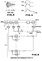
- Fig. 2 shows an example of a waveform of a picked up piano tone.
- waveform data for a section W1 + W2 from rising of the tone to some point of decay thereof for each tone is written, the portion of decay after W2 being discarded.
- the waveform data from W1 to W2 is read out first and then the waveform data of W2 is repeatedly read out.
- the amplitude level of each picked up tone waveform may be standardized to a constant level L0, e.g., maximum level, as shown in Fig. 2 and this standardized level may be stored in the waveform memory 10.
- L0 e.g., maximum level
- the amplitude value can be expressed digitally with high precision even in a low amplitude portion. Since an amplitude envelope is imparted by envelope imparting means 22 and 24 as will be described later, no adverse effect will be produced by adopting such arrangement.
- a depressed key detection and key assigning circuit 14 detects a depressed key in the keyboard 12 and assigns key code data KC representing the key code (i.e., tone pitch) of the detected key and a key-on signal KON indicating that there is a depresssed key to one of empty channels so that they are provided at the timing of this channel.
- key code data KC representing the key code (i.e., tone pitch) of the detected key
- KON indicating that there is a depresssed key
- a touch detection circuit 16 detects which level among the weak, middle and strong levels the key touch strength of the depressed key in the keyboard 12 corresponds to and provides touch level data TD representing the detected touch level in synchronism with the timing of the channel to which the key code KC and the key-on signal KON have been assigned.
- circuits 14 and 16 are operated on a time shared basis and posterior circuits responsive to outputs of these circuits 14 and 16 are also operated on a time shared basis. For convenience of explanation, however, an operation for one channel only will be described below.
- a waveform selection control circuit 18 generates waveform designation data WS in response to the key code data KC and the touch level data TD.
- a waveform to be read out is designated in response to the waveform designation data WS. If, for example, a key code represented by the key code data KC belongs to the first key group, waveform data corresponding to the touch level data TD among waveform data belonging to the first key group is designated for reading.
- An address signal generation circuit 20 generates an address signal AD in response to the key code data KC and the key-on signal KON.
- the waveform data which has been designated by the waveform designation data WS is read out from the waveform memory 10 in response to the address signal AD.
- the designation of address by the address signal AD is performed at a speed corresponding to the key code (tone, pitch) represented by the key code data KC and the tone pitch of the generated tone is determined in accordance with this reading speed.
- the same waveform data is read out at different reading speeds for the respective keys so long as the keys are depressed at a constant key touch level.
- the waveform data WD read out from the waveform memory 10 is supplied to a multiplier 22 in which it is multiplied with envelope shape data ED.
- An envelope signal generation circuit 24 generates envelope shape data ED in response to the key-on signal KON in such a manner that different envelope shapes are produced depending upon whether a damper pedal signal DP is "0" or "1” as shown in Fig. 3.
- the damper pedal signal DP is detected from a damper pedal 26 through a switch or the like means.
- the envelope shape decays gradually after rising and decays rapidly after key-off.
- Parameters such as attack time, attack level, decay time etc. of the envelope shape are controlled key group by key group in response to the key code data KC and also controlled touch level by touch level in response to the touch level data TD.
- waveform data EWD imparted with an envelope shape in accordance with tone pitch, touch response and damper pedal state is provided and this waveform data EWD is supplied to an accumulator 28.
- the accumulator 28 is provided for mixing waveform data for plural channels. Its output waveform data SWD is supplied to a multiplier 30A in which it is multiplied with a cross-fade control signal CF1. The waveform data SWD is supplied also to a resonance tone generation circuit 32 in which it is converted to resonance tone data RWD. The resonance tone data RWD from the resonance tone generation circuit 32 is supplied to a multiplier 30B in which it is multiplied with a cross-fade control signal CF2.
- the resonance tone generation circuit 32 is constructed, e.g., as shown in Fig. 5, of digital delay circuits 31 (shown by square blocks), coefficient multipliers 33 (shown by triangular blocks) and adders 35 (shown by circular blocks with "+" signs therein).
- digital delay circuits 31 shown by square blocks
- coefficient multipliers 33 shown by triangular blocks
- adders 35 shown by circular blocks with "+" signs therein.
- tone waveform data SWD as the input signal IN
- tone waveform data imparting an impression of expansion of a tone which is similar to a tone produced when a damper pedal is ON, i.e., resonance tone data can be obtained as the output signal OUT.
- a cross-fade control signal generation circuit 34 generates the cross-fade control signals CF1 and CF2 in response to the damper pedal signal DP.
- An example of the cross-fade control signals is shown in Fig. 4.
- the cross-fade control signal CF1 is generated in such a manner that its level falls gradually from maximum value 1 to minimum value 0 taking about one second when the damper pedal signal DP has been turned from “0" to "1" (i.e., the damper pedal 26 has been turned ON from the OFF state), maintains the minimum value "0” as long as the signal DP maintains "1” and rises from the minimum value "0" to the maximum value "1” taking about 0.2 second when the signal DP has been turned from "1" to "0” (i.e., the damper pedal 26 has been turned OFF from the ON state).
- the cross-fade control signal CF2 is generated in the form of inverted cross-fade control signal CF1.
- the waveform SWD is supplied to an adder 36 when the damper pedal 26 is OFF whereas the resonance tone data RWD is supplied to the adder 36 when the damper pedal 26 is ON.
- mixed data of the data SWD and RWD which are mixed in the adder 36 at a mixing ratio determined by the values of the cross-fade control signals CF1 and CF2.
- the waveform data as the output of the adder 36 is supplied to a sound system 38 including a digital-to-analog converter, an amplifier and loudspeakers and is sounded therefrom as a tone.
- Fig. 6 shows the second embodiment in which the resonance tone adding portion used in the circuit of Fig. 1 is modified.
- the same component parts as in Fig. 1 are designated by the same reference characters.
- the second embodiment which is a modification of the embodiment of Fig. 1 is different from the embodiment of Fig. 1 in the following two points. Firstly, waveform data SWD from the accumulator 28 is supplied to the adder 36 without passing through the multiplier 30A. Secondly, the multiplier 30B is provided in a prior stage to the resonance tone generation circuit 32. In this case, a similar signal to the cross-fade control signal CF2 of Fig. 4 is supplied as a level control signal LC to the multiplier 30B.
- waveform data SWD is obtained as the output of the adder 36 when the damper pedal 28 is OFF.
- the waveform data SWD is supplied to the resonance tone generation circuit 32 through the multiplier 30B so that the resonance tone data RWD is provided from the circuit 32.
- mixed data of the waveform data SWD and the resonance tone data RWD is supplied as the output of the adder 36.
- the mixing ratio of the resonance tone data RWD to the waveform data SWD is controlled in response to the level control signal LC (corresponding to the cross-fade control signal CF2).
- waveform data which is a mixture of waveform data having the tone pitch corresponding to the depressed key and resonance tone data generated on the basis of this waveform data is obtained.
- This waveform data has a greater ratio of tone componenet of the depressed key that in a case where, as shown in Fig. 1, resonance tone data alone is provided so that this construction is advantageous when it is desired to emphasize the tone of a depressed key.
- the multiplier 30B may be provided in a posterior stage to the resonance tone generation circuit 32.
- Fig. 7 shows the third embodiment of the invnetion in which the mixing ratio control portion used in the circuit of Fig. 1 is modified.
- the same component parts as in Fig. 1 are designated by the same reference characters.
- a feature of this embodiment is that a depression amount detection circuit 40 for detecting an amount of depression of the damper pedal 26 is provided and a detection output A of this detection circuit 40 is supplied to the multiplier 30B as a signal A2 instead of the cross-fade control signal CF2 while a signal A1 obtained by inverting the detection output A by an inverting circuit 42 (i.e., "1 - A") is supplied to the multiplier 30A instead of the cross-fade control signal CF1.
- the waveform data SWD from the accumulator 28 is controlled by the multiplier 30A to decrease in its amplitude level while the resonance tone data RWD from the resonance tone generation circuit 32 is controlled by the multiplier 30B to increase in its amplitude level.
- the adder 36 provides waveform data which is a mixture of the data SWD and RWD at a mixing ratio determined by the values of the signals A1 and A2. If the damper pedal 26 is not depressed, the adder 36 provides the waveform data SWD and, if the damper pedal 26 is depressed most deeply, the adder 36 provides the resonance tone data RWD.
- the performer can set the mixing ratio of the waveform data SWD and the resonance tone data RWD as desired by properly adjusting the amount of depression of the damper pedal 26 whereby a tone color change can be obtained in addition to the damper pedal ON/OFF effect as described with reference to Fig. 1.
- Fig. 8 shows a circuit construction of an embodiment of the electronic musical instrument according to the invention.
- this electronic musical instrument can produce plural tones simultaneously by a time division multiplexing processing in plural channels (e.g., eight channels).
- plural channels e.g., eight channels.
- the same component parts as in Fig. 1 are designated by the same reference characters.
- a damper pedal OFF waveform memory 10A is of a similar construction to the waveform memory 10 in Fig. 1, storing waveform data for each key group in a damper pedal OFF state with respect to each of plural stages of touch levels.
- a damper pedal ON waveform memory 10B stores waveform data sampled from a piano as a natural musical instrument for each key group with respect to each of plural stages of touch levels in the same manner as in the waveform memory 10A except that the damper pedal is not in an OFF state but in an ON state. Since a key has been depressed in the damper pedal ON state in this case, each waveform data represents a mixed waveform of a tone produced by vibration of a string corresponding to the depressed key and tones produced by vibration of other strings due to resonance.
- a waveform to be read out is designated in response to waveform designation data WS from the waveform selection control circuit 18.
- waveform data designated by the waveform designation data WS are read out in parallel from the waveform memories 10A and 10B in response to the address signal AD from the address generation circuit 20.
- the waveform data WD read out from the waveform memory 10A is supplied to a multiplier 21A in which it is multiplied with the cross-fade control signal CF1.
- the waveform data WDB read out from the waveform memory 10B is supplied to a multiplier 21B in which it is multiplied with the cross-fade control signal CF2.
- the cross-fade control signals CF1 and CF2 are, in the same manner as in the above described embodiment, generated by the cross-fade control signal generation circuit 34.
- An example of these cross-fade control signals are shown in Fig. 4.
- the waveform data WDA is supplied to the adder 23 when the damper pedal 26 is OFF and the waveform data WDB is supplied to the adder 23 when the damper pedal 26 is ON.
- the waveform data as the output of the adder 23 is supplied to a multiplier 25 in which it is multiplied with the envelope shape data ED which is generated from the envelope shape generation circuit 24 as shown in Fig. 3.
- waveform data EWD which has been imparted with envelope in accordance with tone pitch, touch level and damper pedal state is obtained.
- This waveform data EWD is supplied to the sound system 38.
- the construction of the mixing ratio control portion can be modified as shown in Fig. 7.
- the output A2 of the depression amount detection circuit 40 is applied to the multiplier 21B instead of the cross-fade control signal CF2 and the output A1 of the inversion circuit 42 is applied to the multiplier 21A instead of the cross-fade control signals CF1.
- the performer can set the mixing ratio of the waveform data WDB including resonance tone to the waveform data WDA as desired by properly adjusting the amount of depression of the damper pedal 26 whereby a tone color change according to the mixing ratio can be obtained in addition to the damper pedal ON/OFF effect shown in Fig. 8.
- a desired tone or a resonance tone corresponding to this tone can be generated as desired and, accordingly, simulation of a damper pedal effect as in a piano can be achieved with high fidelity.
Landscapes
- Engineering & Computer Science (AREA)
- Physics & Mathematics (AREA)
- Acoustics & Sound (AREA)
- Multimedia (AREA)
- General Engineering & Computer Science (AREA)
- Electrophonic Musical Instruments (AREA)
Claims (10)
- Un dispositif générateur de son, comprenant:
un moyen de désignation de hauteur (12), destiné à désigner une hauteur d'un son à générer.
un moyen de génération de son (10A), destiné à générer des informations de forme d'onde correspondant à une forme d'onde d'un son désiré selon une hauteur désignée par le moyen de désignation de hauteur (12), ledit moyen de génération de son (10A) comprenant:a) un moyen de mémoire (10A), destiné à mémoriser les informations de forme d'onde correspondant à la forme d'onde de son désirée, etb) un moyen de lecture (20), destiné à lire les informations de forme d'onde (WDA) dudit moyen de mémoire selon une hauteur désignée par le moyen de désignation de hauteur,un moyen d'actionnement (26) qui peut être actionné indépendamment du moyen de désignation de hauteur,
un moyen de détection, destiné à détecter l'état d'actionnement dudit moyen d'actionnement (26) à fournir une sortie de détection indiquant l'état d'actionnement dudit moyen d'actionnement, et
un moyen de sortie (21A, 21B, 23), destiné à sortir les informations de forme d'onde (WDA) comme premier signal sonore et comme second signal sonore en réponse à ladite sortie de détection,
caractérisé en ce qu'il comprend, en outre:
un moyen de mémoire (10B), destiné à mémoriser les informations de forme d'onde de son résonant (WDB) correspondant à une forme d'onde mixte du son désiré et du son résonant de celui-ci, et
un moyen de lecture (20), destiné à lire les informations de forme d'onde de son résonant (WDB) dudit moyen de mémoire (10B) selon une hauteur désignée par le moyen de désignation de hauteur (12), ledit second signal sonore étant lesdites informations de forme d'onde de son résonant (WDB). - Un dispositif générateur de son suivant la revendication 1, qui comprend, en outre, un moyen de commande de fondu enchaîné (34), destiné à réaliser une commande telle que les informations de forme d'onde (WDA) et les informations de son résonant (WDB) sont sorties en fondu enchaîné lorsque ledit moyen d'actionnement (26) a été actionné.
- Un dispositif générateur de son suivant la revendication 1, qui comprend, en outre, un moyen de commande destiné à réaliser une commande telle que, lorsque ledit moyen d'actionnement (26) a été actionné, les informations de son résonant (WDB) à sortir par le moyen de sortie sont progressivement augmentées ou diminuées tandis que les informations de forme d'onde (WDA) sont sorties par le moyen de sortie.
- Un dispositif générateur de son suivant la revendication 1, qui comprend, en outre, un moyen de commande destiné à réaliser une commande telle que les informations de forme d'onde (WDA) et les informations de son résonant (WDB) sont sorties en combinaison selon un taux de combinaison variable correspondant à ladite sortie de détection.
- Un dispositif générateur de son suivant l'une quelconque des revendications 1 à 4, qui comprend, en outre, un moyen de réglage de courbe enveloppe (24) destiné à régler une courbe enveloppe d'un son généré dans ledit dispositif générateur de son en réponse à ladite sortie de détection.
- Un dispositif générateur de son suivant l'une quelconque des revendications 1 à 5, dans lequel ledit moyen de détection détecte un état d'actionnement MARCHE/ARRET du moyen d'actionnement.
- Un dispositif générateur de son suivant l'une quelconque des revendications 1 à 5, dans lequel ledit moyen de détection détecte une quantité d'actionnement du moyen d'actionnement dans une plage allant d'une quantité minimale à une quantité maximale.
- Un dispositif générateur de son suivant la revendication 7, dans lequel ledit moyen de sortie comprend:
un premier moyen de réglage de niveau (42, 21A), destiné à régler le niveau d'amplitude des informations de forme d'onde (WDA) pour le modifier selon une première caractéristique de modification correspondant à la quantité détectée par le moyen de détection, et
un second moyen de réglage de niveau (40, 21B), destiné à régler le niveau d'amptitude des informations de son résonant (WDB) pour le modifier selon une seconde caractéristique de modification correspondant à la quantité détectée par le moyen de détection qui est différente de ladite première caractéristique de modification. - Un dispositif générateur de son suivant l'une quelconque des revendications 1 à 8, dans lequel ledit moyen d'actionnement comprend une pédale de sourdine.
- Un dispositif générateur de son suivant l'une quelconque des revendications 1 à 9, dans lequel l'un desdits moyens de mémoire (10A) mémorise lesdites informations de forme d'onde (WDA) ayant une caractéristique d'une forme d'onde de son d'un piano naturel joué avec la pédale de sourdine non-actionnée, et l'autre desdits moyens de mémoire (10B) mémorise lesdites informations de forme d'onde de son résonant (WDB) ayant une caractéristique d'une forme d'onde de son d'un piano naturel joué avec la pédale de sourdine actionnée.
Priority Applications (1)
| Application Number | Priority Date | Filing Date | Title |
|---|---|---|---|
| EP92116609A EP0521537B1 (fr) | 1987-10-02 | 1988-10-01 | Dispositif générateur de signal musical |
Applications Claiming Priority (4)
| Application Number | Priority Date | Filing Date | Title |
|---|---|---|---|
| JP62249399A JP2508138B2 (ja) | 1987-10-02 | 1987-10-02 | 楽音信号発装置 |
| JP249400/87 | 1987-10-02 | ||
| JP62249400A JP2560348B2 (ja) | 1987-10-02 | 1987-10-02 | 楽音信号発生装置 |
| JP249399/87 | 1987-10-02 |
Related Child Applications (2)
| Application Number | Title | Priority Date | Filing Date |
|---|---|---|---|
| EP92116609A Division EP0521537B1 (fr) | 1987-10-02 | 1988-10-01 | Dispositif générateur de signal musical |
| EP92116609.6 Division-Into | 1992-09-29 |
Publications (2)
| Publication Number | Publication Date |
|---|---|
| EP0310133A1 EP0310133A1 (fr) | 1989-04-05 |
| EP0310133B1 true EP0310133B1 (fr) | 1994-04-13 |
Family
ID=26539266
Family Applications (2)
| Application Number | Title | Priority Date | Filing Date |
|---|---|---|---|
| EP88116275A Expired - Lifetime EP0310133B1 (fr) | 1987-10-02 | 1988-10-01 | Dispositif générateur de son |
| EP92116609A Expired - Lifetime EP0521537B1 (fr) | 1987-10-02 | 1988-10-01 | Dispositif générateur de signal musical |
Family Applications After (1)
| Application Number | Title | Priority Date | Filing Date |
|---|---|---|---|
| EP92116609A Expired - Lifetime EP0521537B1 (fr) | 1987-10-02 | 1988-10-01 | Dispositif générateur de signal musical |
Country Status (5)
| Country | Link |
|---|---|
| US (2) | US4909121A (fr) |
| EP (2) | EP0310133B1 (fr) |
| KR (1) | KR940001090B1 (fr) |
| DE (2) | DE3889051T2 (fr) |
| HK (1) | HK188796A (fr) |
Families Citing this family (44)
| Publication number | Priority date | Publication date | Assignee | Title |
|---|---|---|---|---|
| JPH0778677B2 (ja) * | 1986-11-28 | 1995-08-23 | ヤマハ株式会社 | 電子楽器のキ−スケ−リング装置 |
| JPH01101590A (ja) * | 1987-10-14 | 1989-04-19 | Casio Comput Co Ltd | 電子楽器 |
| JPH0752352B2 (ja) * | 1988-06-23 | 1995-06-05 | ヤマハ株式会社 | ソフトペダル効果装置 |
| US5000074A (en) * | 1988-06-23 | 1991-03-19 | Yamaha Corporation | Effect imparting device for an electronic musical instrument or the like apparatus |
| US5094136A (en) * | 1989-01-06 | 1992-03-10 | Yamaha Corporation | Electronic musical instrument having plural different tone generators employing different tone generation techniques |
| JPH0769701B2 (ja) * | 1989-05-09 | 1995-07-31 | ヤマハ株式会社 | 楽音波形信号形成装置 |
| US5272274A (en) * | 1989-08-10 | 1993-12-21 | Yamaha Corporation | Electronic musical instrument with reverberation effect |
| US5147970A (en) * | 1989-08-11 | 1992-09-15 | Casio Computer Co., Ltd. | Electronic musical instrument for generating musical tones on the basis of characteristics of input waveform signal |
| US5292997A (en) * | 1989-08-17 | 1994-03-08 | Yamaha Corporation | Touch responsive envelope shape generation device |
| US5256830A (en) * | 1989-09-11 | 1993-10-26 | Yamaha Corporation | Musical tone synthesizing apparatus |
| JP3008419B2 (ja) * | 1990-01-19 | 2000-02-14 | ヤマハ株式会社 | 電子楽器 |
| JPH07113830B2 (ja) * | 1990-03-19 | 1995-12-06 | ヤマハ株式会社 | 電子楽器 |
| JPH03269584A (ja) * | 1990-03-20 | 1991-12-02 | Yamaha Corp | 電子楽器 |
| JPH0774958B2 (ja) * | 1990-06-01 | 1995-08-09 | ヤマハ株式会社 | 楽音合成装置 |
| JP2504298B2 (ja) * | 1990-06-20 | 1996-06-05 | ヤマハ株式会社 | 楽音合成装置 |
| US5198604A (en) * | 1990-09-12 | 1993-03-30 | Yamaha Corporation | Resonant effect apparatus for electronic musical instrument |
| US5252774A (en) * | 1990-10-31 | 1993-10-12 | Yamaha Corporation | Electronic musical instrument having resonance tone generation |
| US5166464A (en) * | 1990-11-28 | 1992-11-24 | Casio Computer Co., Ltd. | Electronic musical instrument having a reverberation |
| JP2650489B2 (ja) * | 1990-11-30 | 1997-09-03 | ヤマハ株式会社 | 電子楽器 |
| JP2664098B2 (ja) * | 1991-04-17 | 1997-10-15 | 株式会社河合楽器製作所 | 電子楽器のペダル装置 |
| JP3243821B2 (ja) * | 1992-02-27 | 2002-01-07 | ヤマハ株式会社 | 電子楽器 |
| JP2565073B2 (ja) * | 1992-03-10 | 1996-12-18 | ヤマハ株式会社 | ディジタル信号処理装置 |
| US5374775A (en) * | 1992-06-09 | 1994-12-20 | Yamaha Corporation | Keyboard instrument for selectively producing mechanical sounds and synthetic sounds without any mechanical vibrations on music wires |
| US5543578A (en) * | 1993-09-02 | 1996-08-06 | Mediavision, Inc. | Residual excited wave guide |
| US5468906A (en) * | 1993-09-02 | 1995-11-21 | Media Vision, Inc. | Sound synthesis model incorporating sympathetic vibrations of strings |
| JPH0784574A (ja) * | 1993-09-14 | 1995-03-31 | Kawai Musical Instr Mfg Co Ltd | 電子楽器 |
| IT1281788B1 (it) * | 1995-04-28 | 1998-03-03 | Generalmusic Spa | Dispositivo di simulazione dell'effetto pedale di risonanza per pianoforti digitali |
| JPH09127941A (ja) * | 1995-10-27 | 1997-05-16 | Yamaha Corp | 電子楽器 |
| FR2747496B1 (fr) * | 1996-04-16 | 1998-05-15 | France Telecom | Procede de simulation de resonances sympathiques sur un instrument de musique electronique |
| JPH09292880A (ja) * | 1996-04-26 | 1997-11-11 | Yamaha Corp | 電子鍵盤楽器 |
| US5827987A (en) * | 1996-06-25 | 1998-10-27 | Kabushiki Kaisha Kawai Gakki Seisakusho | Electronic musical instrument with a variable coefficients digital filter responsive to key touch |
| JP3433896B2 (ja) * | 1998-01-22 | 2003-08-04 | 株式会社河合楽器製作所 | 楽音発生装置 |
| JP3633420B2 (ja) | 2000-02-22 | 2005-03-30 | ヤマハ株式会社 | 楽音発生装置 |
| JP2002311957A (ja) * | 2001-04-17 | 2002-10-25 | Kawai Musical Instr Mfg Co Ltd | 共鳴装置、共鳴方法及び共鳴処理のためのコンピュータプログラム |
| JP4716422B2 (ja) * | 2006-01-19 | 2011-07-06 | 株式会社河合楽器製作所 | 共鳴音発生装置 |
| JP4539590B2 (ja) * | 2006-03-20 | 2010-09-08 | ヤマハ株式会社 | 鍵盤楽器 |
| JP4905284B2 (ja) * | 2007-08-01 | 2012-03-28 | カシオ計算機株式会社 | 鍵盤楽器の共鳴音付加装置 |
| JP5228667B2 (ja) * | 2008-07-24 | 2013-07-03 | ヤマハ株式会社 | 電子鍵盤楽器 |
| US8067685B2 (en) * | 2010-01-07 | 2011-11-29 | Preston Parish | Stringed instrument utilizing sympathetic vibrations |
| US8467551B2 (en) * | 2010-07-30 | 2013-06-18 | Gentex Corporation | Vehicular directional microphone assembly for preventing airflow encounter |
| JP2012203347A (ja) * | 2011-03-28 | 2012-10-22 | Kawai Musical Instr Mfg Co Ltd | 電子音源付きピアノ |
| US10939503B2 (en) * | 2018-04-13 | 2021-03-02 | Lennard A. Gumaer | Programmable signal generator and radio controller |
| JP7243116B2 (ja) | 2018-10-05 | 2023-03-22 | ヤマハ株式会社 | 共鳴音信号発生装置、共鳴音信号発生方法、共鳴音信号発生プログラムおよび電子音楽装置 |
| JP7476501B2 (ja) * | 2019-09-05 | 2024-05-01 | ヤマハ株式会社 | 共鳴音信号発生方法、共鳴音信号発生装置、共鳴音信号発生プログラムおよび電子音楽装置 |
Family Cites Families (21)
| Publication number | Priority date | Publication date | Assignee | Title |
|---|---|---|---|---|
| US4067253A (en) * | 1976-04-02 | 1978-01-10 | The Wurlitzer Company | Electronic tone-generating system |
| JPS52121313A (en) * | 1976-04-06 | 1977-10-12 | Nippon Gakki Seizo Kk | Electronic musical instrument |
| US4211141A (en) * | 1978-03-17 | 1980-07-08 | Jensen Richard W | Pedal control circuits for electronic piano |
| JPS5639593A (en) * | 1979-09-08 | 1981-04-15 | Nippon Musical Instruments Mfg | Electronic musical instrument |
| US4586417A (en) * | 1981-07-28 | 1986-05-06 | Nippon Gakki Seizo Kabushiki Kaisha | Electronic musical instruments provided with reverberation tone generating apparatus |
| JPS5946688A (ja) * | 1982-09-09 | 1984-03-16 | カシオ計算機株式会社 | 電子楽器 |
| JPS5983199A (ja) * | 1982-11-02 | 1984-05-14 | ヤマハ株式会社 | 電子楽器 |
| JPS6052895A (ja) * | 1983-09-02 | 1985-03-26 | ヤマハ株式会社 | 楽音信号発生装置 |
| JPS6052896A (ja) * | 1983-09-02 | 1985-03-26 | ヤマハ株式会社 | 電子楽器 |
| JPS6055398A (ja) * | 1983-09-07 | 1985-03-30 | ヤマハ株式会社 | 電子楽器における波形形成方法 |
| US4779505A (en) * | 1983-09-07 | 1988-10-25 | Nippon Gakki Seizo Kabushiki Kaisha | Electronic musical instrument of full-wave readout system |
| JPS6068387A (ja) * | 1983-09-26 | 1985-04-18 | ヤマハ株式会社 | 電子楽器 |
| JPH0693190B2 (ja) * | 1983-10-26 | 1994-11-16 | ヤマハ株式会社 | 電子楽器 |
| JPH0693189B2 (ja) * | 1983-10-26 | 1994-11-16 | ヤマハ株式会社 | 電子楽器 |
| JPS6093492A (ja) * | 1983-10-28 | 1985-05-25 | 株式会社ダイエー | 音源装置 |
| US4633749A (en) * | 1984-01-12 | 1987-01-06 | Nippon Gakki Seizo Kabushiki Kaisha | Tone signal generation device for an electronic musical instrument |
| DE3569164D1 (en) * | 1984-06-12 | 1989-05-03 | Yamaha Corp | Tone signal generation device |
| US4706537A (en) * | 1985-03-07 | 1987-11-17 | Nippon Gakki Seizo Kabushiki Kaisha | Tone signal generation device |
| JPS61204696A (ja) * | 1985-03-07 | 1986-09-10 | ヤマハ株式会社 | 楽音信号発生装置 |
| US4726276A (en) * | 1985-06-28 | 1988-02-23 | Nippon Gakki Seizo Kabushiki Kaisha | Slur effect pitch control in an electronic musical instrument |
| JPH0754428B2 (ja) * | 1987-04-24 | 1995-06-07 | ヤマハ株式会社 | 楽音信号発生装置 |
-
1988
- 1988-09-27 KR KR1019880012477A patent/KR940001090B1/ko not_active Expired - Fee Related
- 1988-09-30 US US07/252,261 patent/US4909121A/en not_active Ceased
- 1988-10-01 DE DE3889051T patent/DE3889051T2/de not_active Expired - Fee Related
- 1988-10-01 DE DE3856103T patent/DE3856103T2/de not_active Expired - Fee Related
- 1988-10-01 EP EP88116275A patent/EP0310133B1/fr not_active Expired - Lifetime
- 1988-10-01 EP EP92116609A patent/EP0521537B1/fr not_active Expired - Lifetime
-
1991
- 1991-03-19 US US07/671,357 patent/USRE35813E/en not_active Expired - Lifetime
-
1996
- 1996-10-10 HK HK188796A patent/HK188796A/en not_active IP Right Cessation
Also Published As
| Publication number | Publication date |
|---|---|
| EP0310133A1 (fr) | 1989-04-05 |
| EP0521537A3 (en) | 1993-06-16 |
| EP0521537B1 (fr) | 1998-01-07 |
| DE3889051T2 (de) | 1994-08-25 |
| DE3889051D1 (de) | 1994-05-19 |
| KR890007209A (ko) | 1989-06-19 |
| EP0521537A2 (fr) | 1993-01-07 |
| DE3856103T2 (de) | 1998-07-16 |
| KR940001090B1 (ko) | 1994-02-12 |
| HK188796A (en) | 1996-10-18 |
| DE3856103D1 (de) | 1998-02-12 |
| US4909121A (en) | 1990-03-20 |
| USRE35813E (en) | 1998-06-02 |
Similar Documents
| Publication | Publication Date | Title |
|---|---|---|
| US4909121A (en) | Tone signal generation device with reasonance tone effect | |
| JPH09127941A (ja) | 電子楽器 | |
| JPS59105694A (ja) | 電子楽器 | |
| JP2692672B2 (ja) | 楽音信号発生装置 | |
| JPS61204698A (ja) | 楽音信号発生装置 | |
| JPH09330079A (ja) | 楽音信号発生装置及び楽音信号発生方法 | |
| JP3279861B2 (ja) | 楽音信号発生装置 | |
| JP2858120B2 (ja) | 電子楽器 | |
| JP2508138B2 (ja) | 楽音信号発装置 | |
| JP2560348B2 (ja) | 楽音信号発生装置 | |
| JP2698942B2 (ja) | 楽音発生装置 | |
| JP2768458B2 (ja) | 電子楽器 | |
| US5315058A (en) | Electronic musical instrument having artificial string sound source with bowing effect | |
| JP2814699B2 (ja) | 楽音合成装置 | |
| JP2527077B2 (ja) | 電子楽器 | |
| JP2701177B2 (ja) | 楽音発生装置 | |
| JP2943279B2 (ja) | 電子楽器 | |
| JPH0266597A (ja) | 楽音合成装置及び楽音合成方法 | |
| JPH03269493A (ja) | 電子楽器 | |
| JPH07225579A (ja) | 電子楽器 | |
| JPH0498291A (ja) | 電子楽器 | |
| JPH04298790A (ja) | ステレオ装置及びステレオ方法 | |
| JPH05181463A (ja) | 楽音信号発生装置 | |
| JPH056174A (ja) | 楽音信号発生装置 | |
| JPH0519755A (ja) | 電子楽器 |
Legal Events
| Date | Code | Title | Description |
|---|---|---|---|
| PUAI | Public reference made under article 153(3) epc to a published international application that has entered the european phase |
Free format text: ORIGINAL CODE: 0009012 |
|
| AK | Designated contracting states |
Kind code of ref document: A1 Designated state(s): DE GB |
|
| 17P | Request for examination filed |
Effective date: 19890428 |
|
| 17Q | First examination report despatched |
Effective date: 19910313 |
|
| GRAA | (expected) grant |
Free format text: ORIGINAL CODE: 0009210 |
|
| AK | Designated contracting states |
Kind code of ref document: B1 Designated state(s): DE GB |
|
| REF | Corresponds to: |
Ref document number: 3889051 Country of ref document: DE Date of ref document: 19940519 |
|
| PLBE | No opposition filed within time limit |
Free format text: ORIGINAL CODE: 0009261 |
|
| STAA | Information on the status of an ep patent application or granted ep patent |
Free format text: STATUS: NO OPPOSITION FILED WITHIN TIME LIMIT |
|
| 26N | No opposition filed | ||
| REG | Reference to a national code |
Ref country code: GB Ref legal event code: IF02 |
|
| PGFP | Annual fee paid to national office [announced via postgrant information from national office to epo] |
Ref country code: DE Payment date: 20040923 Year of fee payment: 17 |
|
| PG25 | Lapsed in a contracting state [announced via postgrant information from national office to epo] |
Ref country code: DE Free format text: LAPSE BECAUSE OF NON-PAYMENT OF DUE FEES Effective date: 20060503 |
|
| PGFP | Annual fee paid to national office [announced via postgrant information from national office to epo] |
Ref country code: GB Payment date: 20060927 Year of fee payment: 19 |
|
| GBPC | Gb: european patent ceased through non-payment of renewal fee |
Effective date: 20071001 |
|
| PG25 | Lapsed in a contracting state [announced via postgrant information from national office to epo] |
Ref country code: GB Free format text: LAPSE BECAUSE OF NON-PAYMENT OF DUE FEES Effective date: 20071001 |