EP0310233B1 - Verbrennungsregelsystem - Google Patents
Verbrennungsregelsystem Download PDFInfo
- Publication number
- EP0310233B1 EP0310233B1 EP88307500A EP88307500A EP0310233B1 EP 0310233 B1 EP0310233 B1 EP 0310233B1 EP 88307500 A EP88307500 A EP 88307500A EP 88307500 A EP88307500 A EP 88307500A EP 0310233 B1 EP0310233 B1 EP 0310233B1
- Authority
- EP
- European Patent Office
- Prior art keywords
- alarm
- sensor
- parameters
- display
- prioritisation
- Prior art date
- Legal status (The legal status is an assumption and is not a legal conclusion. Google has not performed a legal analysis and makes no representation as to the accuracy of the status listed.)
- Expired - Lifetime
Links
- 238000002485 combustion reaction Methods 0.000 title claims description 36
- 238000000034 method Methods 0.000 claims description 67
- 238000012913 prioritisation Methods 0.000 claims description 29
- 238000012544 monitoring process Methods 0.000 claims description 12
- 230000006870 function Effects 0.000 claims description 10
- 238000012545 processing Methods 0.000 claims description 10
- 238000010276 construction Methods 0.000 claims description 3
- 230000004044 response Effects 0.000 claims description 3
- QVGXLLKOCUKJST-UHFFFAOYSA-N atomic oxygen Chemical compound [O] QVGXLLKOCUKJST-UHFFFAOYSA-N 0.000 description 22
- 229910052760 oxygen Inorganic materials 0.000 description 22
- 239000001301 oxygen Substances 0.000 description 22
- 230000000881 depressing effect Effects 0.000 description 15
- 239000000446 fuel Substances 0.000 description 11
- 239000007789 gas Substances 0.000 description 11
- 239000004020 conductor Substances 0.000 description 8
- 239000000523 sample Substances 0.000 description 8
- 238000003745 diagnosis Methods 0.000 description 6
- 238000010586 diagram Methods 0.000 description 5
- 239000012528 membrane Substances 0.000 description 5
- 230000002159 abnormal effect Effects 0.000 description 4
- 238000001514 detection method Methods 0.000 description 4
- 238000010438 heat treatment Methods 0.000 description 4
- 238000004886 process control Methods 0.000 description 4
- UGFAIRIUMAVXCW-UHFFFAOYSA-N Carbon monoxide Chemical compound [O+]#[C-] UGFAIRIUMAVXCW-UHFFFAOYSA-N 0.000 description 3
- 230000001276 controlling effect Effects 0.000 description 3
- 239000003546 flue gas Substances 0.000 description 3
- 238000004458 analytical method Methods 0.000 description 2
- 238000009529 body temperature measurement Methods 0.000 description 2
- 239000000567 combustion gas Substances 0.000 description 2
- 230000003750 conditioning effect Effects 0.000 description 2
- 238000012937 correction Methods 0.000 description 2
- 230000001419 dependent effect Effects 0.000 description 2
- 230000000994 depressogenic effect Effects 0.000 description 2
- 238000012423 maintenance Methods 0.000 description 2
- 238000005259 measurement Methods 0.000 description 2
- 238000005070 sampling Methods 0.000 description 2
- 238000013024 troubleshooting Methods 0.000 description 2
- OKTJSMMVPCPJKN-UHFFFAOYSA-N Carbon Chemical compound [C] OKTJSMMVPCPJKN-UHFFFAOYSA-N 0.000 description 1
- XAGFODPZIPBFFR-UHFFFAOYSA-N aluminium Chemical compound [Al] XAGFODPZIPBFFR-UHFFFAOYSA-N 0.000 description 1
- 229910052782 aluminium Inorganic materials 0.000 description 1
- 239000004411 aluminium Substances 0.000 description 1
- 229910002091 carbon monoxide Inorganic materials 0.000 description 1
- 239000011248 coating agent Substances 0.000 description 1
- 238000000576 coating method Methods 0.000 description 1
- 238000013480 data collection Methods 0.000 description 1
- 230000007423 decrease Effects 0.000 description 1
- 238000002405 diagnostic procedure Methods 0.000 description 1
- 238000005516 engineering process Methods 0.000 description 1
- 238000004868 gas analysis Methods 0.000 description 1
- 229910002804 graphite Inorganic materials 0.000 description 1
- 239000010439 graphite Substances 0.000 description 1
- 238000005286 illumination Methods 0.000 description 1
- 239000004973 liquid crystal related substance Substances 0.000 description 1
- 230000007257 malfunction Effects 0.000 description 1
- 239000000463 material Substances 0.000 description 1
- 238000011022 operating instruction Methods 0.000 description 1
- 230000000737 periodic effect Effects 0.000 description 1
- 238000010926 purge Methods 0.000 description 1
- 230000001105 regulatory effect Effects 0.000 description 1
- 238000012552 review Methods 0.000 description 1
- 238000012163 sequencing technique Methods 0.000 description 1
- 230000011664 signaling Effects 0.000 description 1
- 230000000007 visual effect Effects 0.000 description 1
Images




Classifications
-
- H—ELECTRICITY
- H05—ELECTRIC TECHNIQUES NOT OTHERWISE PROVIDED FOR
- H05K—PRINTED CIRCUITS; CASINGS OR CONSTRUCTIONAL DETAILS OF ELECTRIC APPARATUS; MANUFACTURE OF ASSEMBLAGES OF ELECTRICAL COMPONENTS
- H05K7/00—Constructional details common to different types of electric apparatus
- H05K7/14—Mounting supporting structure in casing or on frame or rack
- H05K7/1462—Mounting supporting structure in casing or on frame or rack for programmable logic controllers [PLC] for automation or industrial process control
- H05K7/1484—Electrical diagrams relating to constructional features, e.g. signal routing within PLC; Provisions for disaster recovery, e.g. redundant systems
-
- F—MECHANICAL ENGINEERING; LIGHTING; HEATING; WEAPONS; BLASTING
- F23—COMBUSTION APPARATUS; COMBUSTION PROCESSES
- F23N—REGULATING OR CONTROLLING COMBUSTION
- F23N5/00—Systems for controlling combustion
- F23N5/24—Preventing development of abnormal or undesired conditions, i.e. safety arrangements
- F23N5/242—Preventing development of abnormal or undesired conditions, i.e. safety arrangements using electronic means
-
- F—MECHANICAL ENGINEERING; LIGHTING; HEATING; WEAPONS; BLASTING
- F23—COMBUSTION APPARATUS; COMBUSTION PROCESSES
- F23N—REGULATING OR CONTROLLING COMBUSTION
- F23N5/00—Systems for controlling combustion
- F23N5/26—Details
-
- F—MECHANICAL ENGINEERING; LIGHTING; HEATING; WEAPONS; BLASTING
- F23—COMBUSTION APPARATUS; COMBUSTION PROCESSES
- F23N—REGULATING OR CONTROLLING COMBUSTION
- F23N1/00—Regulating fuel supply
- F23N1/02—Regulating fuel supply conjointly with air supply
-
- F—MECHANICAL ENGINEERING; LIGHTING; HEATING; WEAPONS; BLASTING
- F23—COMBUSTION APPARATUS; COMBUSTION PROCESSES
- F23N—REGULATING OR CONTROLLING COMBUSTION
- F23N2223/00—Signal processing; Details thereof
- F23N2223/04—Memory
-
- F—MECHANICAL ENGINEERING; LIGHTING; HEATING; WEAPONS; BLASTING
- F23—COMBUSTION APPARATUS; COMBUSTION PROCESSES
- F23N—REGULATING OR CONTROLLING COMBUSTION
- F23N2223/00—Signal processing; Details thereof
- F23N2223/08—Microprocessor; Microcomputer
-
- F—MECHANICAL ENGINEERING; LIGHTING; HEATING; WEAPONS; BLASTING
- F23—COMBUSTION APPARATUS; COMBUSTION PROCESSES
- F23N—REGULATING OR CONTROLLING COMBUSTION
- F23N2223/00—Signal processing; Details thereof
- F23N2223/38—Remote control
-
- F—MECHANICAL ENGINEERING; LIGHTING; HEATING; WEAPONS; BLASTING
- F23—COMBUSTION APPARATUS; COMBUSTION PROCESSES
- F23N—REGULATING OR CONTROLLING COMBUSTION
- F23N2231/00—Fail safe
- F23N2231/20—Warning devices
-
- F—MECHANICAL ENGINEERING; LIGHTING; HEATING; WEAPONS; BLASTING
- F23—COMBUSTION APPARATUS; COMBUSTION PROCESSES
- F23N—REGULATING OR CONTROLLING COMBUSTION
- F23N5/00—Systems for controlling combustion
- F23N5/003—Systems for controlling combustion using detectors sensitive to combustion gas properties
-
- F—MECHANICAL ENGINEERING; LIGHTING; HEATING; WEAPONS; BLASTING
- F23—COMBUSTION APPARATUS; COMBUSTION PROCESSES
- F23N—REGULATING OR CONTROLLING COMBUSTION
- F23N5/00—Systems for controlling combustion
- F23N5/003—Systems for controlling combustion using detectors sensitive to combustion gas properties
- F23N5/006—Systems for controlling combustion using detectors sensitive to combustion gas properties the detector being sensitive to oxygen
-
- G—PHYSICS
- G05—CONTROLLING; REGULATING
- G05B—CONTROL OR REGULATING SYSTEMS IN GENERAL; FUNCTIONAL ELEMENTS OF SUCH SYSTEMS; MONITORING OR TESTING ARRANGEMENTS FOR SUCH SYSTEMS OR ELEMENTS
- G05B2219/00—Program-control systems
- G05B2219/20—Pc systems
- G05B2219/24—Pc safety
- G05B2219/24063—Select signals as function of priority, importance for diagnostic
-
- G—PHYSICS
- G05—CONTROLLING; REGULATING
- G05B—CONTROL OR REGULATING SYSTEMS IN GENERAL; FUNCTIONAL ELEMENTS OF SUCH SYSTEMS; MONITORING OR TESTING ARRANGEMENTS FOR SUCH SYSTEMS OR ELEMENTS
- G05B2219/00—Program-control systems
- G05B2219/20—Pc systems
- G05B2219/24—Pc safety
- G05B2219/24103—Graphical display of proces as function of detected alarm signals
Definitions
- Oxygen and combustibles analysers are often used to analyse combustion gases in data collection and combustion control systems. These analysers are effective in improving product quality and combustion efficiency, as compared to systems without combustion gas analysis.
- a major drawback to these analysers, however, is that sampling, sensing, and heating systems that are required for their proper operation tend to be complex and prone to failure.
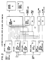
- the solenoid digital output routines 105 control gas flow to the analyser during a calibration cycle by operating the appropriate control valve to adjust zero setting, span and blowback.
- the operator interface status decoding routines 108 determine the display status conditions and initiate the proper action required by signals inputted from the keyboard interface. These routines also regulate data flow sent to the display interface 24.
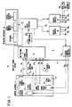
- the sensor assembly 11 provides various signal inputs, including signals proportional to oxygen concentration, combustibles concentration, oxygen sensor block temperature, combustibles sensor block temperature, and a cold junction compensator used in conjunction with the thermocouples used for temperature measurement.
- the sensor assembly 11 also contains heaters which are used to heat the sensors and the sample gas to predetermined, constant temperatures.
- the signal inputs are then fed to electronic circuits of the process controller 12 and are fed through the multiplexer and signal conditioners 21 and the A/D converter 22. These signals are then manipulated by firmware resident in the microprocessor 23. The results of these manipulations are made available to the user via the operator interface unit 24. Much of this same information is made available to analog outputs and digital outputs. The analog outputs are used to provide a direct indication of measured parameters, whereas the digital outputs provide information on the status of a particular variable. Heater control circuitry is used to convert logic level signals from the microprocessor 23 to the power levels needed by the sensor heaters.
- Sensor zero and span alarms 132 for both the oxygen and combustible sensors 14, 15 are always displayed because the alarms are also not necessarily caused by other analyser fault conditions.
- the analyser power alarm 133 has priority over any further alarms. If a power switch (not shown) is turned off, neither the cold junction compensator 18 ( Figure 1) nor the sensor heaters ( Figure 1) have power. Thus, both a cold junction compensator alarm and a temperature alarm will occur as a direct result of turning off the power and are therefore redundant indications of a known condition.
- the cold junction compensator 18 ( Figure 1) is an integrated part of the temperature measurement of both the flange manifold and the combustible sensor block. If the cold junction compensator fails, these temperatures will be erroneous, the the sensor outputs will be invalid. Therefore, the cold junction compensator alarm 134 has priority over the remaining alarms because if the cold junction compensator reading is invalid, the other alarms will occur as a direct result of this condition, and are therefore redundant.
- the system constantly monitors analyser parameters and informs the control system of abnormal conditions.
- the control system can default immediately to a predetermined condition.
- the system automatically prioritises analyser alarms and displays only relevant alarms. These alarms are displayed in easy to understand English sentences.
- the digital outputs provide a remote indication of system status as well as an additional safety output. These outputs inform the operator of abnormal conditions. A more detailed explanation of these conditions is then available through the operator interface.
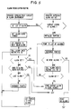
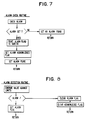
- the routine When the operator depresses the NEXT SCREEN key 37 in the alarm environment, the routine obtains the list of alarms, obtains the alarm being viewed and sets the pointer to the next valid alarm.
- the next valid alarm is the next alarm which can be displayed given the current alarm and the priority structure of the system. For example, with reference to Figure 4, if the flange manifold temperature is out of range, the next valid alarm is the CO block temperature alarm.
- the alarm acknowledge routine is executed. If there is an existing alarm, the pointer is initialised. Then, the pointer is incremented and, if there is another alarm, an alarm LED flash bit is set. If there are no more alarms, then the alarm acknowledged check routine is executed and, if an unacknowledged alarm is found, the alarm LED flash bit is set. Otherwise, if any alarm is found the pointer is set to the next valid alarm. Otherwise, the routine loops back to increment the pointer and search for any further alarms.
Landscapes
- Engineering & Computer Science (AREA)
- Combustion & Propulsion (AREA)
- General Engineering & Computer Science (AREA)
- Mechanical Engineering (AREA)
- Chemical & Material Sciences (AREA)
- Microelectronics & Electronic Packaging (AREA)
- Automation & Control Theory (AREA)
- Computer Networks & Wireless Communication (AREA)
- Investigating Or Analyzing Materials By The Use Of Electric Means (AREA)
- Testing And Monitoring For Control Systems (AREA)
- Regulation And Control Of Combustion (AREA)
- Feedback Control In General (AREA)
- Feeding And Controlling Fuel (AREA)
Claims (11)
- Steuersystem mit: einem Sensoraufbau (11), der Sensoreinrichtungen für die Bereitstellung von Ausgangssignalen hat, welche für Parameter kennzeichnend sind, Steuereinrichtungen (12), die Eingabeeinrichtungen (21) für den Empfang der Ausgangssignale haben, welche durch die Sensoreinrichtungen bereitgestellt werden, Überwachungseinrichtungen für das kontinuierliche Überwachen der Parameter und für das Erzeugen von Alarmsignalen, Anzeigeeinrichtungen (23) für das Anzeigen von Alarmzuständen unter Ansprechen auf die Alarmsignale, Prioritätseinrichtungen (126), um automatisch eine Priorität für die Anzeige der Alarmzustände zu erzeugen, und einem Speicher,
dadurch gekennzeichnet, daß
das Steuersystem ein Verbrennungssteuersystem für die Steuerung eines Verbrennungsvorganges ist,
die Steuereinrichtung (12) eine Prozeßsteuereinrichtung ist, welche so betreibbar ist,
daß sie den Verbrennungsprozeß steuert,
die Sensoreinrichtung so betreibbar ist, daß sie die Ausgangssignale bereitstellt, welche zumindest einen Parameter des Verbrennungssteuerprozesses kennzeichnen,
die Steuereinrichtung (12) eine Signalverarbeitungseinheit (23) beinhaltet, die auf die Ausgangssignale anspricht, welche von der Sensoreinrichtung bereitgestellt werden, um Steuer- bzw. Regelausgangswerte zu erzeugen, um eine gewünschte Betriebsweise des Verbrennungssteuerprozesses aufrechtzuerhalten,
die Überwachungseinrichtung einen Teil der Signalverarbeitungseinrichtung (23) bildet und so betreibbar ist, daß sie kontinuierlich Parameter des Verbrennungssteuersystems einschließlich zumindest eines Parameters des Verbrennungssteuerprozesses überwacht, der von der Sensoreinrichtung bereitgestellt wird, und so, daß sie ein Alarmsignal erzeugt, sobald irgendeiner der überwachten Parameter von einem Sollwert abweicht,
die Prioritätseinrichtung (126) automatisch so betreibbar ist, daß sie den Alarmsignalen Priorität gewährt, um eine Anzeige ausgewählter Alarmzustände bereitzustellen, und zwar auf der Basis der Kenntnis von internen Vorgängen eines Analysatorsystems, was ein unmittelbares Ergebnis eines Aufbaues des Analysatorsystems ist,
und das Verbrennungssteuersystem und die Prioritätseinrichtung (126) durch ein in dem Speicher gespeichertes Programm so betreibbar sind, daß sie zweifelhafte Sensorablesungen nicht beachten. - System nach Anspruch 1, wobei eine erste Gruppe der überwachten Parameter bezüglich einer korrekten Betriebsweise des Sensoraufbaues (11) vorher festgelegt ist, und daß eine zweite Gruppe der Parameter als Funktion von Betriebsarten für das Verbrennungssteuersystem auswählbar ist, wobei das System eine Zwischenebenen-Einrichtung (24) für den Benutzer aufweist, die mit der Signalverarbeitungseinrichtung (23) gekoppelt ist, um dem Benutzer die Möglichkeit zu geben, für die zweite Gruppe von Parametern der Signalverarbeitungseinrichtung (23) ausgewählte Sollwerte aufzugeben.
- System nach Anspruch 2, wobei die Prioritätseinrichtung (126) so betreibbar ist, daß sie die Anzeige eines Alarmzustandes im Falle der Abweichung eines der Parameter der ersten Gruppe von den jeweiligen Sollwerten und die Unterdrückung der Anzeige eines Alarmzustandes für irgendeinen der Parameter der zweiten Gruppe bei Vorhandensein eines Alarmzustandes für irgendeinen der Parameter der ersten Gruppe bewirkt.
- System nach Anspruch 3, wobei bestimmte Parameter der ersten Gruppe interne Systemvariable sind und die Prioritätseinrichtung (126) so betreibbar ist, daß sie die Anzeige eines Alarmzustandes bewirkt, sobald diese bestimmten Parameter von Sollwerten abweichen, wobei ein weiterer Parameter der ersten Gruppe eine Anzeige dafür ist, ob Energie zumindest an dem Sensoraufbau (111) aufgebracht wird, und wobei die Prioritätseinrichtung (126) so betreibbar ist, daß sie die Anzeige eines Alarmzustandes bewirkt, sobald dem Sensoraufbau keine Energie zugeführt wird, und wobei die Parameter der zweiten Gruppe Zustände des Sensors anzeigen und die Prioritätseinrichtung (126) so betreibbar ist, daß sie eine Anzeige von deren Alarmzuständen nur bei Abwesenheit von Alarmzuständen für alle Parameter der ersten Gruppe anzeigt.
- System nach Anspruch 3, wobei die Prioritätseinrichtung (126) so betreibbar ist, daß sie die Zwischenebenen-Einrichtung (24) für den Benutzer steuert, um bestimmte Alarmzustände auf der Anzeigeeinrichtung (32) anzuzeigen, und so betreibbar ist, daß sie Alarmsignale erzeugt, welche anderen Alarmzuständen entspricht, um diese auf eine Zwischenebene (128) des Steuersystems zu geben, um eine Einstellung des Betriebs des Systems entsprechend den erzeugten Alarmzuständen zu bewirken.
- System nach Anspruch 3, wobei die Sensoreinrichtung eine Mehrzahl von Sensoren (14 bis 18) aufweist und wobei die Prioritätseinrichtung (126) auf ein Alarmsignal anspricht, welches eine Anzeige für einen Fehlerzustand eines gegebenen Sensors ist, um die Anzeige eines Alarmzustandes zu unterdrücken, der eine Abweichung des Sollwertes desjenigen Parameters anzeigt, der durch diesen einen Sensor überwacht wird, und um das Alarmsignal auf ein Interface bzw. eine Zwischenebene (128) des Steuersystems zu geben, um eine Überführung des Systembetriebs in einen bekannten, sicheren Zustand zu bewirken.
- System nach Anspruch 1, wobei der Sensoraufbau (11) zumindest erste und zweite Parametersensoreinrichtungen hat, die jeweils Ausgangssignale bereitstellen, welche eine Anzeige für unterschiedliche Parameter des Prozesses sind, wobei die Eingabeeinrichtungen (21) des Prozeßsteuersystems (12) so ausgelegt sind, daß sie die von den ersten und zweiten Parametersensoreinrichtungen bereitgestellten Signale empfangen, wobei die Überwachungseinrichtung Komponentenabfühleinrichtungen aufweist, um Betriebszustände der ersten und zweiten Sensoreinrichtungen kontinuierlich zu überwachen und um ein Alarmsignal zu erzeugen, sobald ein Prozeßparameter oder der Betriebszustand eines Sensors von einem Sollwert abweicht, und wobei die Anzeigeeinrichtung (32) durch eine Zwischenebeneneinrichtung (24) für den Benutzer bereitgestellt wird, die mit der Signalverarbeitungseinrichtung (23) gekoppelt ist.
- System nach Anspruch 7, wobei die Zwischenebenen-Einrichtung (24) für den Benutzer eine Tastatur (31) aufweist, wobei die Systemparameter vorher festgelegt werden und wobei Alarmzustände (124) des Prozesses und Abstimmalarmzustände (122), welche eine Funktion des gesteuerten Prozesses sind, durch den Benutzer über die Tastatur (31) einstellbare Sollwerte haben, die auf der Kenntnis des Benutzers von dem Prozeß beruhen.
- System nach Anspruch 8, wobei die Prioritätseinrichtung (126) so betreibbar ist, daß sie eine Anzeige eines Alarmzustandes bei Abweichung irgendeines der Systemparameter von seinem jeweiligen Sollwert bewirkt und daß sie die Anzeige eines Alarmzustandes für irgendeinen der Sensorbetriebszustände unterdrückt, wenn ein Alarmzustand für irgendeinen der Systemparameter vorhanden ist.
- System nach Anspruch 8, wobei die Prioritätseinrichtung (126) so betreibbar ist, daß sie die Anzeige der Meldung eines Alarmzustandes für Prozeßparameter bewirkt, sobald sie auftreten, und die Anzeige der Meldung eines Alarmzustandes für einen Sensorbetriebszustand nur dann bewirkt, wenn kein Alarmzustand für einen Prozeßparameter vorhanden ist.
- System nach Anspruch 10, wobei die Alarmprioritätseinrichtung (126) so betreibbar ist, daß sie für Alarmzustände, die auf der Anzeigeeinrichtung (32) für Alarmzustände für Sensorbetriebszustände der ersten Sensoreinrichtung die Prioritätsgewährung gegenüber der zweiten Sensoreinrichtung bereitstellt.
Applications Claiming Priority (2)
| Application Number | Priority Date | Filing Date | Title |
|---|---|---|---|
| US07/084,689 US4885573A (en) | 1987-08-12 | 1987-08-12 | Diagnostic system for combustion controller |
| US84689 | 1987-08-12 |
Related Child Applications (2)
| Application Number | Title | Priority Date | Filing Date |
|---|---|---|---|
| EP9393107941A Division EP0559241A3 (en) | 1987-08-12 | 1988-08-12 | Housings for control systems |
| EP93107941.2 Division-Into | 1993-05-15 |
Publications (3)
| Publication Number | Publication Date |
|---|---|
| EP0310233A2 EP0310233A2 (de) | 1989-04-05 |
| EP0310233A3 EP0310233A3 (de) | 1991-04-24 |
| EP0310233B1 true EP0310233B1 (de) | 1995-02-15 |
Family
ID=22186611
Family Applications (2)
| Application Number | Title | Priority Date | Filing Date |
|---|---|---|---|
| EP9393107941A Withdrawn EP0559241A3 (en) | 1987-08-12 | 1988-08-12 | Housings for control systems |
| EP88307500A Expired - Lifetime EP0310233B1 (de) | 1987-08-12 | 1988-08-12 | Verbrennungsregelsystem |
Family Applications Before (1)
| Application Number | Title | Priority Date | Filing Date |
|---|---|---|---|
| EP9393107941A Withdrawn EP0559241A3 (en) | 1987-08-12 | 1988-08-12 | Housings for control systems |
Country Status (6)
| Country | Link |
|---|---|
| US (1) | US4885573A (de) |
| EP (2) | EP0559241A3 (de) |
| JP (1) | JPH01147217A (de) |
| AU (2) | AU610919B2 (de) |
| CA (1) | CA1332964C (de) |
| DE (1) | DE3853036T2 (de) |
Families Citing this family (32)
| Publication number | Priority date | Publication date | Assignee | Title |
|---|---|---|---|---|
| US5076780A (en) * | 1988-09-01 | 1991-12-31 | Honeywell Inc. | Digital controller component failure detection for gas appliance ignition function |
| US5075867A (en) * | 1988-12-23 | 1991-12-24 | Bull Hn Information Systems Inc. | Method for limiting spurious resonant cavity effects in electronic equipment |
| AU630993B2 (en) * | 1989-08-09 | 1993-11-12 | Alcatel N.V. | Module disabling circuit |
| NL9000789A (nl) * | 1990-04-04 | 1991-11-01 | Interconnection B V | Beveiligingsschakeling voor een verwarmingsinrichting. |
| JP3061429B2 (ja) * | 1991-02-01 | 2000-07-10 | パロマ工業株式会社 | 燃焼器具の使用状況監視装置 |
| US5353238A (en) * | 1991-09-12 | 1994-10-04 | Cloos International Inc. | Welding robot diagnostic system and method of use thereof |
| US5191313A (en) * | 1991-09-12 | 1993-03-02 | Honeywell Inc. | Method of continuous monitoring of process variables of varying grades of a product within a process control system |
| US5499023A (en) * | 1992-05-27 | 1996-03-12 | Kaye Instruments, Inc. | Method of and apparatus for automated sensor diagnosis through quantitative measurement of one of sensor-to-earth conductance or loop resistance |
| US5236328A (en) * | 1992-09-21 | 1993-08-17 | Honeywell Inc. | Optical flame detector performance tester |
| US5725308A (en) * | 1994-12-23 | 1998-03-10 | Rtd Technology, Inc. | Quick registering thermometer |
| US6247921B1 (en) | 1996-05-23 | 2001-06-19 | American Standard International Inc. | Apparatus for generating a spark |
| US5984502A (en) * | 1996-06-14 | 1999-11-16 | The Foxboro Company | Keypad annunciator graphical user interface |
| US5829878A (en) * | 1996-10-15 | 1998-11-03 | Micro Idea Instruments, Ltd. | Digital fever thermometer having an illuminated display |
| US6339743B1 (en) * | 1997-10-31 | 2002-01-15 | Holley Performance Products, Inc. | Ignition system and method of programming an ignition system |
| US5997280A (en) * | 1997-11-07 | 1999-12-07 | Maxon Corporation | Intelligent burner control system |
| US6389330B1 (en) | 1997-12-18 | 2002-05-14 | Reuter-Stokes, Inc. | Combustion diagnostics method and system |
| US6341519B1 (en) | 1998-11-06 | 2002-01-29 | Reuter-Stokes, Inc. | Gas-sensing probe for use in a combustor |
| US6277268B1 (en) | 1998-11-06 | 2001-08-21 | Reuter-Stokes, Inc. | System and method for monitoring gaseous combustibles in fossil combustors |
| KR100304907B1 (ko) * | 1999-02-26 | 2001-09-24 | 구자홍 | 가스온풍기의 운전 제어장치 및 그 방법 |
| KR100333489B1 (ko) * | 1999-12-29 | 2002-04-25 | 김형국 | 버너 컨트롤 회로 테스트 장치 |
| DE60111359T2 (de) | 2000-01-28 | 2006-05-11 | Robertshaw Controls Co. | Diagnosegerät für feuerungsanlage |
| US7128818B2 (en) * | 2002-01-09 | 2006-10-31 | General Electric Company | Method and apparatus for monitoring gases in a combustion system |
| TW200636192A (en) * | 2005-03-22 | 2006-10-16 | Miura Kogyo Kk | Damper position adjusting device and combustion apparatus having such damper adjusting device |
| WO2007067702A2 (en) * | 2005-12-06 | 2007-06-14 | Growmax Investments Limited | Presonal thermometer with timer |
| US8109759B2 (en) * | 2006-03-29 | 2012-02-07 | Fives North America Combustion, Inc. | Assured compliance mode of operating a combustion system |
| US7869890B2 (en) * | 2006-09-06 | 2011-01-11 | Honeywell International Inc. | Keyboards having multiple groups of keys in the management of a process control plant |
| US7870854B2 (en) * | 2007-03-12 | 2011-01-18 | FPI Fireplace Products International Ltd | Closed-loop control system for heating systems |
| CN101749727B (zh) * | 2008-12-09 | 2013-08-28 | 中海网络科技股份有限公司 | 一种高性价比的燃煤热载体炉燃烧冗余控制系统 |
| US20160245515A1 (en) * | 2015-02-24 | 2016-08-25 | Elwha Llc | Nitrogen-reduced combustion air |
| US10307855B2 (en) * | 2016-03-29 | 2019-06-04 | Illinois Tool Works Inc. | Impending thermal shutdown alert system and thermal shutdown process |
| DE102018200429A1 (de) * | 2018-01-11 | 2019-07-11 | Bayerische Motoren Werke Aktiengesellschaft | Störungsbehandlung in einem System |
| KR102095202B1 (ko) * | 2019-09-26 | 2020-03-31 | 주식회사 나노켐 | 연통 이탈 감지 시스템 |
Citations (1)
| Publication number | Priority date | Publication date | Assignee | Title |
|---|---|---|---|---|
| DE3335481A1 (de) * | 1983-09-30 | 1985-04-18 | Diehl GmbH & Co, 8500 Nürnberg | Warnanzeigeeinrichtung |
Family Cites Families (24)
| Publication number | Priority date | Publication date | Assignee | Title |
|---|---|---|---|---|
| DE1086365B (de) * | 1959-05-25 | 1960-08-04 | Mikrowellen Ges M B H Deutsche | Verschlussklappe fuer Arbeitsraeume von Mikrowellenherden |
| DE1108757B (de) * | 1959-11-27 | 1961-06-15 | Siemens Ag | Baugruppe fuer Anlagen der elektrischen Nachrichtentechnik |
| US3988730A (en) * | 1974-12-31 | 1976-10-26 | Motorola, Inc. | Multiple parameter monitoring and readout system with sampling of parameters of higher priority than the highest parameter which is out of tolerance |
| AU506160B2 (en) * | 1976-04-07 | 1979-12-13 | Forney International Inc. | Burner control system |
| JPS5427467A (en) * | 1977-08-01 | 1979-03-01 | Casio Comput Co Ltd | Electronic watch with alarm function |
| US4359746A (en) * | 1979-09-04 | 1982-11-16 | Kaye Instruments, Inc. | Zero level correction apparatus |
| US4336529A (en) * | 1980-02-19 | 1982-06-22 | Pitney Bowes Inc. | Postage meter having shielded keyboard to protect against electromagnetic radiation |
| JPS6025919B2 (ja) * | 1980-11-19 | 1985-06-20 | 株式会社日立製作所 | 電子部品集合装置 |
| US4464653A (en) * | 1981-12-09 | 1984-08-07 | The Bendix Corporation | Combustible gas detection system |
| US4430520A (en) * | 1982-04-07 | 1984-02-07 | Tibbetts Industries, Inc. | Transducer shielding enclosure |
| US4482261A (en) * | 1982-07-15 | 1984-11-13 | Owens-Corning Fiberglas Corporation | Method for simultaneous reference junction compensation of a plurality of thermocouples |
| WO1984001083A1 (en) * | 1982-08-25 | 1984-03-15 | Matsushita Electric Industrial Co Ltd | Radio-wave sealing device |
| JPS5969623A (ja) * | 1982-10-14 | 1984-04-19 | Matsushita Electric Ind Co Ltd | 燃料遮断制御装置 |
| US4538138A (en) * | 1982-12-17 | 1985-08-27 | American District Telegraph Company | Integrated security system having a multiprogrammed controller |
| US4543567A (en) * | 1983-04-14 | 1985-09-24 | Tokyo Shibaura Denki Kabushiki Kaisha | Method for controlling output of alarm information |
| US4567317A (en) * | 1983-07-07 | 1986-01-28 | Computer Products, Inc. | EMI/RFI Protected enclosure |
| DE3334481A1 (de) * | 1983-09-22 | 1985-04-11 | Peter 1000 Berlin Stocklöw | In der hoehe verstellbares waschbecken |
| JPS60127888A (ja) * | 1983-12-15 | 1985-07-08 | Citizen Watch Co Ltd | 液晶表示装置 |
| JPS6122124A (ja) * | 1984-07-07 | 1986-01-30 | Hanshin Electric Co Ltd | 燃焼機器用異常警報方法 |
| MX157711A (es) * | 1984-10-10 | 1988-12-09 | Grace W R & Co | Mejoras a estacion de trabajo antiestatica electricamente conductora en recipientes de alto riesgo |
| JPS61161337A (ja) * | 1985-01-08 | 1986-07-22 | Matsushita Electric Ind Co Ltd | 燃焼器具の制御装置 |
| JPS61250708A (ja) * | 1985-04-30 | 1986-11-07 | Mitsubishi Electric Corp | プラント診断装置 |
| US4623266A (en) * | 1985-09-24 | 1986-11-18 | Rosemount Inc. | Cold junction compensation for thermocouple |
| US4671688A (en) * | 1985-10-02 | 1987-06-09 | Honeywell Inc. | Shielded keyboard |
-
1987
- 1987-08-12 US US07/084,689 patent/US4885573A/en not_active Expired - Lifetime
-
1988
- 1988-08-09 AU AU20605/88A patent/AU610919B2/en not_active Ceased
- 1988-08-10 CA CA000574354A patent/CA1332964C/en not_active Expired - Fee Related
- 1988-08-12 JP JP63200292A patent/JPH01147217A/ja active Pending
- 1988-08-12 EP EP9393107941A patent/EP0559241A3/en not_active Withdrawn
- 1988-08-12 DE DE3853036T patent/DE3853036T2/de not_active Expired - Fee Related
- 1988-08-12 EP EP88307500A patent/EP0310233B1/de not_active Expired - Lifetime
-
1991
- 1991-02-13 AU AU71022/91A patent/AU629099B2/en not_active Ceased
Patent Citations (1)
| Publication number | Priority date | Publication date | Assignee | Title |
|---|---|---|---|---|
| DE3335481A1 (de) * | 1983-09-30 | 1985-04-18 | Diehl GmbH & Co, 8500 Nürnberg | Warnanzeigeeinrichtung |
Also Published As
| Publication number | Publication date |
|---|---|
| DE3853036T2 (de) | 1995-06-08 |
| DE3853036D1 (de) | 1995-03-23 |
| AU7102291A (en) | 1991-05-30 |
| EP0559241A3 (en) | 1994-08-24 |
| JPH01147217A (ja) | 1989-06-08 |
| AU629099B2 (en) | 1992-09-24 |
| EP0310233A2 (de) | 1989-04-05 |
| EP0559241A2 (de) | 1993-09-08 |
| US4885573A (en) | 1989-12-05 |
| EP0310233A3 (de) | 1991-04-24 |
| CA1332964C (en) | 1994-11-08 |
| AU2060588A (en) | 1989-02-16 |
| AU610919B2 (en) | 1991-05-30 |
Similar Documents
| Publication | Publication Date | Title |
|---|---|---|
| US4885573A (en) | Diagnostic system for combustion controller | |
| US5010322A (en) | Housing for a process controller | |
| JP7368612B2 (ja) | 一酸化炭素とメタンの同時測定可能な燃焼分析装置 | |
| US5479350A (en) | Exhaust gas temperature indicator for a gas turbine engine | |
| US6006167A (en) | Gas burner monitor and diagnostic apparatus | |
| US7839277B2 (en) | Monitoring system and temperature controller | |
| JPS6324148A (ja) | 酸素および可燃物分析器用自動較正および制御装置 | |
| JP7362912B2 (ja) | 一酸化炭素及びメタンのデュアル測定による燃焼分析器 | |
| NO161197B (no) | Gassdetektor. | |
| US6339373B1 (en) | Sensor device providing indication of device health | |
| US8103393B2 (en) | Aircraft exhaust gas temperature monitor | |
| US4569223A (en) | Method of and apparatus for multiple detector measurement of an environmental parameter | |
| US4357300A (en) | Apparatus for process analysis | |
| CA1338221C (en) | Housing for a process controller | |
| US3070988A (en) | Oxygen analyzer-standardizer | |
| JP3551514B2 (ja) | 配水モニタの計測器校正操作方法 | |
| KR200307562Y1 (ko) | 발전소 가스누설경보장치카드 진단장치 | |
| CA2232314C (en) | Gas burner monitor and diagnostic apparatus | |
| Bender | Standard hydrogen monitoring system-B operation and maintenance manual | |
| KR100726055B1 (ko) | 자동 온도 조절기의 성능 측정장치 | |
| KR0150301B1 (ko) | 자동차 엔진의 자가진단 표시장치 | |
| Schneider | Standard Hydrogen Monitoring System-C operation and maintenance manual | |
| JPS6137175A (ja) | ガス機器監視制御システム | |
| KR19990001693A (ko) | 서미스터의 이상상태 감지방법 |
Legal Events
| Date | Code | Title | Description |
|---|---|---|---|
| PUAI | Public reference made under article 153(3) epc to a published international application that has entered the european phase |
Free format text: ORIGINAL CODE: 0009012 |
|
| AK | Designated contracting states |
Kind code of ref document: A2 Designated state(s): DE FR GB IT NL |
|
| RAP1 | Party data changed (applicant data changed or rights of an application transferred) |
Owner name: INTERNATIONAL CONTROL AUTOMATION FINANCE S.A. |
|
| PUAL | Search report despatched |
Free format text: ORIGINAL CODE: 0009013 |
|
| AK | Designated contracting states |
Kind code of ref document: A3 Designated state(s): DE FR GB IT NL |
|
| 17P | Request for examination filed |
Effective date: 19910816 |
|
| 17Q | First examination report despatched |
Effective date: 19930105 |
|
| GRAA | (expected) grant |
Free format text: ORIGINAL CODE: 0009210 |
|
| AK | Designated contracting states |
Kind code of ref document: B1 Designated state(s): DE FR GB IT NL |
|
| XX | Miscellaneous (additional remarks) |
Free format text: TEILANMELDUNG 93107941.2 EINGEREICHT AM 12/08/88. |
|
| REF | Corresponds to: |
Ref document number: 3853036 Country of ref document: DE Date of ref document: 19950323 |
|
| ET | Fr: translation filed | ||
| ITF | It: translation for a ep patent filed | ||
| PLBE | No opposition filed within time limit |
Free format text: ORIGINAL CODE: 0009261 |
|
| STAA | Information on the status of an ep patent application or granted ep patent |
Free format text: STATUS: NO OPPOSITION FILED WITHIN TIME LIMIT |
|
| 26N | No opposition filed | ||
| PGFP | Annual fee paid to national office [announced via postgrant information from national office to epo] |
Ref country code: GB Payment date: 19970716 Year of fee payment: 10 |
|
| PGFP | Annual fee paid to national office [announced via postgrant information from national office to epo] |
Ref country code: FR Payment date: 19970717 Year of fee payment: 10 |
|
| PGFP | Annual fee paid to national office [announced via postgrant information from national office to epo] |
Ref country code: NL Payment date: 19970721 Year of fee payment: 10 |
|
| PGFP | Annual fee paid to national office [announced via postgrant information from national office to epo] |
Ref country code: DE Payment date: 19970804 Year of fee payment: 10 |
|
| PG25 | Lapsed in a contracting state [announced via postgrant information from national office to epo] |
Ref country code: GB Free format text: LAPSE BECAUSE OF NON-PAYMENT OF DUE FEES Effective date: 19980812 |
|
| PG25 | Lapsed in a contracting state [announced via postgrant information from national office to epo] |
Ref country code: NL Free format text: LAPSE BECAUSE OF NON-PAYMENT OF DUE FEES Effective date: 19990301 |
|
| GBPC | Gb: european patent ceased through non-payment of renewal fee |
Effective date: 19980812 |
|
| PG25 | Lapsed in a contracting state [announced via postgrant information from national office to epo] |
Ref country code: FR Free format text: LAPSE BECAUSE OF NON-PAYMENT OF DUE FEES Effective date: 19990430 |
|
| NLV4 | Nl: lapsed or anulled due to non-payment of the annual fee |
Effective date: 19990301 |
|
| PG25 | Lapsed in a contracting state [announced via postgrant information from national office to epo] |
Ref country code: DE Free format text: LAPSE BECAUSE OF NON-PAYMENT OF DUE FEES Effective date: 19990601 |
|
| REG | Reference to a national code |
Ref country code: FR Ref legal event code: ST |
|
| PG25 | Lapsed in a contracting state [announced via postgrant information from national office to epo] |
Ref country code: IT Free format text: LAPSE BECAUSE OF NON-PAYMENT OF DUE FEES;WARNING: LAPSES OF ITALIAN PATENTS WITH EFFECTIVE DATE BEFORE 2007 MAY HAVE OCCURRED AT ANY TIME BEFORE 2007. THE CORRECT EFFECTIVE DATE MAY BE DIFFERENT FROM THE ONE RECORDED. Effective date: 20050812 |