EP0311073A2 - Appareil d'exercice pour effectuer des mouvements contrôlés d'articulations du corps - Google Patents
Appareil d'exercice pour effectuer des mouvements contrôlés d'articulations du corps Download PDFInfo
- Publication number
- EP0311073A2 EP0311073A2 EP88116566A EP88116566A EP0311073A2 EP 0311073 A2 EP0311073 A2 EP 0311073A2 EP 88116566 A EP88116566 A EP 88116566A EP 88116566 A EP88116566 A EP 88116566A EP 0311073 A2 EP0311073 A2 EP 0311073A2
- Authority
- EP
- European Patent Office
- Prior art keywords
- frame
- support
- training device
- treatment
- support elements
- Prior art date
- Legal status (The legal status is an assumption and is not a legal conclusion. Google has not performed a legal analysis and makes no representation as to the accuracy of the status listed.)
- Withdrawn
Links
Images


Classifications
-
- A—HUMAN NECESSITIES
- A61—MEDICAL OR VETERINARY SCIENCE; HYGIENE
- A61H—PHYSICAL THERAPY APPARATUS, e.g. DEVICES FOR LOCATING OR STIMULATING REFLEX POINTS IN THE BODY; ARTIFICIAL RESPIRATION; MASSAGE; BATHING DEVICES FOR SPECIAL THERAPEUTIC OR HYGIENIC PURPOSES OR SPECIFIC PARTS OF THE BODY
- A61H1/00—Apparatus for passive exercising; Vibrating apparatus; Chiropractic devices, e.g. body impacting devices, external devices for briefly extending or aligning unbroken bones
- A61H1/02—Stretching or bending or torsioning apparatus for exercising
Definitions
- the invention relates to a body training device for the controlled articulation movement of body sections by means of pivoting and / or lifting and lowering support and / or support elements arranged in a treatment rack, which can be driven by motors via interposed steering gears.
- Body training devices of this type move the body sections placed on the support elements, e.g. the back, thighs and lower legs and their joints without the need for muscle tension.
- the support or support elements consist of padded plates or frames which are articulated in the treatment rack and are set in a pivoting or lifting and lowering movements by a motor which is fixedly arranged in the treatment rack via steering gear and V-belt transmissions.
- a major disadvantage of these devices is that when the support elements are pivoted, a pushing movement is exerted on the body of the user lying on the cushion surface, which, for example, when the upper body rests on the cushion, leads the person towards the feet via the cushion , here stationary, pushes the buttocks and legs upholstery.
- the result is a slow, gradual change in the position of the body, which gradually loses contact with the upper body pad and with the hip joint the right one for the treatment Position is pushed out.
- special fixed holding brackets have been provided for the user, on which he can hold his hands and from time to time bring his body back into the correct position on the upholstery. Similar disadvantageous effects result when the support elements for the upper and lower legs of the user perform pivoting movements.
- the invention has for its object to improve the known body training devices so that the aforementioned disadvantages are avoided and additional advantages, which will be explained in more detail below, are achieved.
- the support elements are arranged so as to be longitudinally displaceable between travel limit stops on support frames which can be pivoted or raised and lowered in the treatment frame. It is thereby achieved that the upholstery support surfaces can adapt to each of the constantly changing movement positions of the corresponding position of the overlying body section, since they are displaceable on the supporting frame receiving them, i.e. the contact between the body and the upholstery surface is not subject to any sliding action and that on the upholstery surfaces the person lying on the floor does not change its position in relation to these contact surfaces; it remains in the correct position it was in at the start of treatment
- return devices connected to the support elements can be provided on the support frame or the treatment racks, which can be subjected to elastic or tensile or compressive action in one and / or both displacement directions, so that the support elements on the support frame against the action of Gravity can be balanced.
- the return devices can consist of gas pressure springs or also of pull weights with cable bypasses or possibly also controllable hydraulic cylinder units.
- the support frames can have a fixed axle mounted in the treatment rack with radial extension levers, which are connected to the drive motor arranged in the treatment rack via articulated crank rods or by means of transfer rollers guided on eccentric disks, this drive motor expediently being designed as a geared motor with one or two transverse drives as a controllable DC motor is.
- This can then be controlled by means of a control and regulating device in such a way that it causes the support frame to be retracted into a preselected position after a definable time or after a shutdown command has been entered at a defined speed. It is thereby possible to bring the support frame with the support elements back into the most favorable position for the user for the end of the treatment or for the start of the next treatment.
- the swivel angle or the distance of the lifting and lowering path of the support frame can be changed and specified by appropriate design of the handlebar gears or also by limited stepping controls of the drive motors, which results in the possibility of gradually increasing the stress on the body joints of the users, ie to begin with smaller swivel angles and to increase them continuously over the course of the treatment period.
- the motor drive units used to generate the movements of the body support elements and the mechanical transmission devices assigned to them are designed and designed in such a way that they work as vibration and shock-free as possible, vibration phenomena of the housing could not be prevented in the known body movement training devices; This is probably because, on the one hand, the load on the drive units and also on the transmission devices due to the different loads on the body support elements and the constantly necessary reversals of movement are very different and, furthermore, the housing, which is usually made of one piece and made of sheet metal, with a relatively large, flat area, is particularly special forms vibration-sensitive resonance body. Attempts to eliminate such vibration phenomena on the housing by dividing it and applying insulation materials have so far not led to satisfactory results and have considerably increased the manufacturing outlay.
- the invention is therefore another object of not only reducing the vibrations of the housing without such effort, but practically eliminating them.
- the body support elements with their drive motors and the associated transmission and possibly control devices are arranged in a frame which, standing freely on the floor, is surrounded by a self-supporting, self-supporting housing which is also free-standing and can be detached therewith is connected by vibration-free coupling elements.
- the adjustment of the frame and the self-supporting housing with respect to their installation on the floor is achieved in that the frame and the self-supporting housing each have their own height-adjustable elastic feet known per se.
- the frame has a preferably rectangular base frame, which is enclosed at a distance from a corresponding base frame assigned to the self-supporting housing, adjacent sections of both frames having tab extensions with upwardly open recesses for receiving fastening bolts from known to be arranged between the two tab extensions have elastic buffer elements.
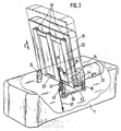
- a trough-shaped support frame 2 is fixedly connected to a pivot axis 3 in the treatment frame 1, which is mounted at 4 in the treatment frame.
- the axis 3 also has fixedly connected radial shoulder levers 5 and 6, on the free ends of which transfer rollers 7 and 8 are supported. These transfer rollers 7 and 8 roll on the outer circumference of eccentric discs 9 and 10, which are seated on the output shafts 11 and 12 of a gear 14 flanged to the DC motor 13 arranged in the treatment rack 1.
- the trough-shaped support frame 2 carries, here for the upper and lower legs of the user not shown support pads 15, which are mounted in a manner not shown in the direction of the double arrow S shown on it, the displacement path being limited by path limit stops, also not shown; the possible displacement of the support pad 15 in the direction away from the axis 3 is indicated by dash-dotted lines.
- the support frame 22 is also connected to an axle 23 which is fixedly mounted at 24 in the treatment frame 1.
- the support pad 35 intended here for the upper body is longitudinally displaceable on the support frame 22 in the direction of the double arrow S shown in parallel rails 36 from the position drawn in full lines to the position indicated by broken lines.
- the weight of the support pad 35 is balanced by means of a pull cable connected to the support pad 35 at 38 and guided via deflection rollers 40, 41 and 42, which is tension-loaded in the direction of the arrow, for example by a weight or a spring (not shown).
- the motor 33 drives a crank rod 43 via a flanged gear 34 and the transverse output 44 and a lever 39 seated thereon, which is articulated to a radial shoulder lever 25 which is fixedly connected to the axle 23.
- the frame 51 (cf. FIG. 3) has a rectangular base frame 51a, which here carries a drive motor 52 with a flanged gear 53 and a link mechanism 54 coupled to it on a crossbeam pair 51b and base feet 51c with a support plate 51d, and which links this to the body support element designated 55 set in motion.
- This body support element 55 is in turn movable about an axis 56, which is also supported in supports 56a on supports 51e in the frame 51.
- the floor frame 51a stands on the floor with feet 57 which, as indicated, are adjustable in height.
- the self-supporting housing 58 likewise has a rectangular base frame 58a. which is arranged at a distance 51b from the floor frame 51a of the frame 51 and stands on the floor with its own, also height-adjustable feet 59.
- the bottom frame 8a of the self-supporting housing 58 encloses the bottom frame 51a of the frame 51 with the aforementioned distance 51b.
- Both base frames 51a and 58a have a plurality of tab extensions 40 and 41 with recesses 40a and 41a open at the top, into which fastening bolts 42 can be inserted, with which the elastic buffer elements 43 which can be inserted between the two base frames 51a and 58a can be detachably attached.
Landscapes
- Health & Medical Sciences (AREA)
- Epidemiology (AREA)
- Pain & Pain Management (AREA)
- Physical Education & Sports Medicine (AREA)
- Rehabilitation Therapy (AREA)
- Life Sciences & Earth Sciences (AREA)
- Animal Behavior & Ethology (AREA)
- General Health & Medical Sciences (AREA)
- Public Health (AREA)
- Veterinary Medicine (AREA)
- Rehabilitation Tools (AREA)
Applications Claiming Priority (4)
| Application Number | Priority Date | Filing Date | Title |
|---|---|---|---|
| DE3733795 | 1987-10-07 | ||
| DE19873733795 DE3733795A1 (de) | 1987-10-07 | 1987-10-07 | Koerpertrainiergeraet zur gesteuerten gelenkbewegung von koerperabschnitten |
| DE8802519U | 1988-02-26 | ||
| DE8802519U DE8802519U1 (de) | 1988-02-26 | 1988-02-26 | Körperbewegungs-Trainiergerät |
Publications (2)
| Publication Number | Publication Date |
|---|---|
| EP0311073A2 true EP0311073A2 (fr) | 1989-04-12 |
| EP0311073A3 EP0311073A3 (fr) | 1989-10-04 |
Family
ID=25860538
Family Applications (1)
| Application Number | Title | Priority Date | Filing Date |
|---|---|---|---|
| EP88116566A Withdrawn EP0311073A3 (fr) | 1987-10-07 | 1988-10-06 | Appareil d'exercice pour effectuer des mouvements contrôlés d'articulations du corps |
Country Status (1)
| Country | Link |
|---|---|
| EP (1) | EP0311073A3 (fr) |
Family Cites Families (6)
| Publication number | Priority date | Publication date | Assignee | Title |
|---|---|---|---|---|
| AT380395B (de) * | 1984-11-05 | 1986-05-12 | Gerhard Ing Hengl | Massagegeraet fuer die unteren extremitaeten |
| FR2575921B1 (fr) * | 1985-01-17 | 1987-03-20 | Materiel Orthopedique Cie Gle | Appareil de mobilisation d'un membre inferieur |
| US4671257A (en) * | 1985-01-23 | 1987-06-09 | Invacare Corporation | Continuous passive motion exercise apparatus |
| EP0216758A1 (fr) * | 1985-04-03 | 1987-04-08 | PIPER, David John | Machine d'entrainement |
| DE3521470A1 (de) * | 1985-06-14 | 1987-02-05 | Baehr Heinz | Bewegungsschiene |
| AT388287B (de) * | 1986-01-21 | 1989-05-26 | Soevegjarto Harald | Einrichtung zur gestuetzten bewegung des beines eines patienten |
-
1988
- 1988-10-06 EP EP88116566A patent/EP0311073A3/fr not_active Withdrawn
Also Published As
| Publication number | Publication date |
|---|---|
| EP0311073A3 (fr) | 1989-10-04 |
Similar Documents
| Publication | Publication Date | Title |
|---|---|---|
| EP2435008B1 (fr) | Dispositif pour le traitement thérapeutique et/ou pour l'entraînement des extrémités inférieures d'une personne | |
| DE1478056A1 (de) | Verfahren zum Muskeltraining und Geraet zur Durchfuehrung des Verfahrens | |
| DE202018106308U1 (de) | Trainer für Kletterübungen | |
| DE2251808C3 (de) | Zahnärztlicher Patientenstuhl mit Parallelogrammtragarm | |
| WO2009143808A1 (fr) | Appareil de gymnastique | |
| DE102009049161A1 (de) | Arbeits- und Montagetisch | |
| DE3819276A1 (de) | Koerpertrainingsgeraet zum trainieren der muskulatur | |
| EP1098684B1 (fr) | Appareil de conditionnement physique | |
| DE60208657T2 (de) | Vorrichtung für muskelentspannung | |
| DE3037619A1 (de) | Streck- und beugegeraet fuer heilgymnastik | |
| EP0311073A2 (fr) | Appareil d'exercice pour effectuer des mouvements contrôlés d'articulations du corps | |
| EP0561106A2 (fr) | Appareil pour effectuer des exercices passifs | |
| EP3380054B1 (fr) | Dispositif et procédé d'entraînement | |
| DE8713438U1 (de) | Körpertrainiergerät zur gesteuerten Gelenkbewegung von Körperabschnitten | |
| DE3733795A1 (de) | Koerpertrainiergeraet zur gesteuerten gelenkbewegung von koerperabschnitten | |
| DE4218646A1 (de) | Vorrichtung zum Muskeltraining | |
| WO1993024190A1 (fr) | Dispositif de musculation | |
| DE1174227B (de) | Gymnastikgeraet zur Ausfuehrung aktiver und passiver Bewegungen des Koerpers | |
| EP1654956B1 (fr) | Dispositif de support pour la réhabilitation de personnes physiquement handicapées | |
| DE102006002548A1 (de) | Trainingsgerät | |
| DE3800496C2 (fr) | ||
| DE10316688B4 (de) | Therapie- und/oder Trainingsgerät | |
| DE8533045U1 (de) | Trainingsgerät | |
| DE3814559C2 (fr) | ||
| AT409455B (de) | Vorrichtung zur rehabilitation der wirbelsäule |
Legal Events
| Date | Code | Title | Description |
|---|---|---|---|
| PUAI | Public reference made under article 153(3) epc to a published international application that has entered the european phase |
Free format text: ORIGINAL CODE: 0009012 |
|
| AK | Designated contracting states |
Kind code of ref document: A2 Designated state(s): BE FR IT NL SE |
|
| PUAL | Search report despatched |
Free format text: ORIGINAL CODE: 0009013 |
|
| AK | Designated contracting states |
Kind code of ref document: A3 Designated state(s): BE FR IT NL SE |
|
| STAA | Information on the status of an ep patent application or granted ep patent |
Free format text: STATUS: THE APPLICATION IS DEEMED TO BE WITHDRAWN |
|
| 18D | Application deemed to be withdrawn |
Effective date: 19900405 |