EP0315207B2 - Système et méthode pour commander automatiquement la vitesse d'un véhicule par rapport à une vitesse de croisière désirée avec mécanisme de mise hors circuit - Google Patents
Système et méthode pour commander automatiquement la vitesse d'un véhicule par rapport à une vitesse de croisière désirée avec mécanisme de mise hors circuit Download PDFInfo
- Publication number
- EP0315207B2 EP0315207B2 EP88118447A EP88118447A EP0315207B2 EP 0315207 B2 EP0315207 B2 EP 0315207B2 EP 88118447 A EP88118447 A EP 88118447A EP 88118447 A EP88118447 A EP 88118447A EP 0315207 B2 EP0315207 B2 EP 0315207B2
- Authority
- EP
- European Patent Office
- Prior art keywords
- vehicle speed
- speed
- predetermined
- control unit
- signal
- Prior art date
- Legal status (The legal status is an assumption and is not a legal conclusion. Google has not performed a legal analysis and makes no representation as to the accuracy of the status listed.)
- Expired - Lifetime
Links
Images


Classifications
-
- B—PERFORMING OPERATIONS; TRANSPORTING
- B60—VEHICLES IN GENERAL
- B60K—ARRANGEMENT OR MOUNTING OF PROPULSION UNITS OR OF TRANSMISSIONS IN VEHICLES; ARRANGEMENT OR MOUNTING OF PLURAL DIVERSE PRIME-MOVERS IN VEHICLES; AUXILIARY DRIVES FOR VEHICLES; INSTRUMENTATION OR DASHBOARDS FOR VEHICLES; ARRANGEMENTS IN CONNECTION WITH COOLING, AIR INTAKE, GAS EXHAUST OR FUEL SUPPLY OF PROPULSION UNITS IN VEHICLES
- B60K31/00—Vehicle fittings, acting on a single sub-unit only, for automatically controlling vehicle speed, i.e. preventing speed from exceeding an arbitrarily established velocity or maintaining speed at a particular velocity, as selected by the vehicle operator
- B60K31/06—Vehicle fittings, acting on a single sub-unit only, for automatically controlling vehicle speed, i.e. preventing speed from exceeding an arbitrarily established velocity or maintaining speed at a particular velocity, as selected by the vehicle operator including fluid pressure actuated servomechanism in which the vehicle velocity affecting element is actuated by fluid pressure
- B60K31/10—Vehicle fittings, acting on a single sub-unit only, for automatically controlling vehicle speed, i.e. preventing speed from exceeding an arbitrarily established velocity or maintaining speed at a particular velocity, as selected by the vehicle operator including fluid pressure actuated servomechanism in which the vehicle velocity affecting element is actuated by fluid pressure and means for comparing one electrical quantity, e.g. voltage, pulse, waveform, flux, or the like, with another quantity of a like kind, which comparison means is involved in the development of a pressure which is fed into the controlling means
- B60K31/102—Vehicle fittings, acting on a single sub-unit only, for automatically controlling vehicle speed, i.e. preventing speed from exceeding an arbitrarily established velocity or maintaining speed at a particular velocity, as selected by the vehicle operator including fluid pressure actuated servomechanism in which the vehicle velocity affecting element is actuated by fluid pressure and means for comparing one electrical quantity, e.g. voltage, pulse, waveform, flux, or the like, with another quantity of a like kind, which comparison means is involved in the development of a pressure which is fed into the controlling means where at least one electrical quantity is set by the vehicle operator
- B60K31/105—Vehicle fittings, acting on a single sub-unit only, for automatically controlling vehicle speed, i.e. preventing speed from exceeding an arbitrarily established velocity or maintaining speed at a particular velocity, as selected by the vehicle operator including fluid pressure actuated servomechanism in which the vehicle velocity affecting element is actuated by fluid pressure and means for comparing one electrical quantity, e.g. voltage, pulse, waveform, flux, or the like, with another quantity of a like kind, which comparison means is involved in the development of a pressure which is fed into the controlling means where at least one electrical quantity is set by the vehicle operator in a memory, e.g. a capacitor
- B60K31/107—Vehicle fittings, acting on a single sub-unit only, for automatically controlling vehicle speed, i.e. preventing speed from exceeding an arbitrarily established velocity or maintaining speed at a particular velocity, as selected by the vehicle operator including fluid pressure actuated servomechanism in which the vehicle velocity affecting element is actuated by fluid pressure and means for comparing one electrical quantity, e.g. voltage, pulse, waveform, flux, or the like, with another quantity of a like kind, which comparison means is involved in the development of a pressure which is fed into the controlling means where at least one electrical quantity is set by the vehicle operator in a memory, e.g. a capacitor the memory being digital
Definitions
- the present invention relates to a system and method for automatically controlling a vehicle speed to a desired cruise speed according to the preambles of claims 1 and 10, respectively.
- ASCD Automatic Speed Control
- EP-A-0171287 a system and method of the type mentioned at the beginning are disclosed.
- the automatic speed controlling function described above is released when the driver actuates a clutch pedal or brake pedal.
- the vehicle speed can exceed the set cruising speed .
- the accelerator pedal depression is halted, the vehicle can again run at the set cruise speed after the speed reduction caused by an engine brake.
- a microcomputer is installed which controls a throttle valve actuator according to a vehicle speed difference between the actual vehicle speed and set vehicle speed in the above-described vehicle speed controlling system. An opening angle of a throttle valve is adjusted through the actuation of the throttle actuator.
- the microcomputer is adapted to cancel the automatic speed control process if the actual vehicle speed does not fall in a predetermined speed range (for example between 48 and 136 km/h) in which the speed control works adequately.
- the microcomputer is adapted to inhibit a power supply to the throttle actuator if the actual vehicle speed is inappropriate for the cruising speed (for example 45 km/h or below) since it is uncontrollable speed.
- controlling means constituted by the microcomputer described above often erroneously detects the vehicle speed being unsuitable for adequate speed control as a controllable vehicle speed so that inappropriate automatic vehicle speed control is performed.
- Fig. 1 is an electrical circuit of a system for automatically controlling a vehicle speed to a desired cruise speed according to the present invention.
- a DC power supply (battery) denoted by 1 is connected between a horn 7 and ground.
- a switch 2 called an ignition switch is connected between a positive pole of the battery 1 and a fuse 3.
- a horn relay 5 connected to a horn switch 6 is connected between the positive pole of the battery 1 and horn 7.
- Numeral 8 denotes a cruising main switch which can be placed on an ON position or on an OFF position.
- Numeral 9 denotes a cruise relay connected in series with the ignition switch 2 via the fuse 3.
- the main switch 8 is a self-holding switch which is self-held by means of the cruising relay 9 and is installed on a part of an instrument panel (not shown ).
- Numeral 10 denotes a main lamp which illuminates when the main switch 8 is turned on.
- a normally closed clutch switch 11 is connected to the self-holding relay 9 and is open when a clutch of a vehicular transmission is depressed and a normally closed brake switch 12 is connected to the clutch switch 11 and is open when a brake pedal is depressed. These clutch and brake switches are connected to an input terminal T 1 of a control unit 30. It is noted that a cut relay and inhibitor switch are connected in series in place of the brake and clutch switches 11 and 12 in the case of an equipment of an automatic transmission on the vehicle.
- a stop lamp 16 which illuminates when a stop lamp switch 15 is turned on upon a depression of the brake pedal.
- a set/cruise switch 17 which is turned on when the vehicle speed is set as the cruising speed and the set vehicle speed is reduced during the cruising run is connected to an input terminal T 2 of the control unit 30.
- Numeral 19 denotes a cancel switch which is turned on when the driver has an intention to release forcibly the cruising mode therethrough. It is noted that these switches are installed on a part of a steering wheel. One contact of each switch 17, 18, and 19 is connected to either of the input terminals T 2 and T 3 of the control unit 30.
- Numeral 20 denotes a vehicle speed sensor outputting the vehicle speed signal and which is connected to the control unit 30.
- the control unit 30 includes a microcomputer which receives on and off signals from the various switches, discriminates various conditions on the basis of such on and off signals, and controls an actuator 31 enclosed with a dot line, for actuating a throttle valve provided in the vehicular engine.
- the actuator 31 is of a positive pressure type adjusting an opening angle of the throttle valve using a compressed air, comprising a release valve 31a for discharging the compressed air from a compressed air tank to the atmosphere, an air valve 31b for opening the compressed air to the atmosphere, and an air supply valve 31c for supplying the compressed air.
- a throttle wire connected to a diaphragm actuated by these valves causes control for the opening angle of the throttle valve.
- a tank for reserving the compressed air is installed as a drive source of the actuator 31.
- a pressure switch 31d is installed in the tank which is turned on when the compressed air pressure exceeds a constant value.
- a vehicle speed determining circuit 40 is connected to the vehicle speed sensor 20.
- the vehicle speed determining circuit 40 is installed independently of the control unit 30.
- An output signal of the vehicle speed determining circuit 40 is supplied to an AND circuit 41.
- a transistor 42 with its bias circuit (not shown) is connected to an output end of the AND circuit 41.
- a relay having a normally open contact 43 is connected between an input terminal T 5 of the control unit 30 and actuator 31. The relay 43 supplies the power to the actuator 31 when the transistor 42 is conducted and a magnet portion thereof is energized.
- a base of a transistor T r is connected with a resistor R 1 and a capacitor C 1 for eliminating noise and the output end of the vehicle speed sensor 20 to receive an analog quantity indicating the vehicle speed information.
- a collector of the transistor T r is connected to a constant voltage (e.g., dc 5 volts) supply circuit (not shown) provided in the control unit 30 via a resistor R 2 .
- a pulse signal A 1 having a rectangular shape and a period corresponding to the vehicle speed is supplied to a monostable multivibrator 40a. The pulse signal A 1 is generated in response to an intermittent signal derived from the vehicle speed sensor 20 by means of the transistor T r .
- the monostable multivibrator 40a is connected to an inverting input terminal of a comparator 40b via a resistor R 3 and a capacitor C 2 .
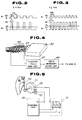
- the multivibrator 40a produces a rectangular pulse signal A 2 having a pulsewidth of T as shown in Figs. 2 and 3 in accordance with the input signal A 1 at each rising edge of the input signal A 1 .
- the pulse signal A 2 is smoothed by means of the resistor R 3 and the capacitor C 2 so that an average voltage signal A 3 of the pulse train signal A 2 is supplied to the inverting input terminal of the comparator 40b.
- V L of the voltage signal A 3 will be described with reference to Fig. 2.
- V L 5 x T x f L , wherein f L denotes an inverted number of the pulse period of the pulse signal A 1 ,i.e., the frequency of the pulse signal A 1 when the vehicle speed V is below the predetermined vehicle speed V TH .
- V H 5 x T x f H
- f H denotes the inverted number of the pulse signal period, i.e., the frequency of the pulse signal A 1 when the vehicle speed V is above the predetermined speed V TH .
- the value of the voltage signal A 3 becomes increased. As the vehicle speed increases, the value of the voltage signal A 3 is also increased. It is noted that the value of the predetermined speed V TH is set with the speed below which the cruising speed is not appropriate to be taken into consideration.
- a non-inverting input terminal of the comparator receives a reference voltage signal V o .
- the value of the reference voltage signal V o is set as follows. V L ⁇ V o ⁇ V H
- V L denotes the value of the voltage signal A 3 when the vehicle cruises at a low speed
- V H denotes the other value of the voltage signal A 3 when the vehicle cruises at a high speed.
- the comparator 40b when the value of the voltage signal A 3 is below the reference voltage signal V o , the comparator 40b outputs a high level signal A 4 .
- the comparator 40b When the value of the voltage signal exceeds the reference voltage signal V o , the comparator 40b outputs a low level signal A 4
- the output signal of the comparator 40b is supplied to an inverter 40c and the one input terminal of the AND circuit 41. Hence, the low level signal is supplied to the AND circuit 41 when the vehicle speed is low and the high level signal is supplied to the AND circuit 41 when the vehicle speed is high.
- An output signal of an electric field intensity determining circuit 44 shown in Fig. 4 is supplied to the other input terminal of the AND circuit 41.
- an electric field intensity measuring circuit 47 measures an induced voltage of a loop coil 46 wound around a harness 45 extended about a connector part of the control unit as shown in Fig. 4. The measured voltage value is checked to determine whether it is above a predetermined voltage value by means of an electric field intensity determining circuit 44. If the measured voltage value is above the predetermined value (strong electric field), the L level signal is supplied to the AND circuit 41. If the measured voltage value is below the predetermined volt value, the H level signal is supplied to the AND circuit 41.
- the AND circuit 41 outputs the H level signal so that the transistor 42 is conducted and the relay 43 is turned on to supply the power to the actuator 31.
- the cruising relay 9 is energized and is held in the ON position so that the main lamp 10 is illuminated. Then the input terminals T 1 and T 4 of the control unit receive the power supply voltage from the battery 1.
- the input terminal T 1 of the control unit 30 is connected to the output terminal T 5 via a normally open contact of a relay, a coil thereof receiving the power supply by means of a switching transistor conducted upon receipt of an ON signal from the microcomputer.
- the microcomputer does not output to the above-described switching transistor so that the input terminal T 1 is not connected to the output terminal T 5 .
- the control unit 30 errorneously detects the vehicle speed so that the input terminal T 1 is connected to the output terminal T 5 , the power supply to the actuator 31 cannot be carried out since the relay 43 remains off.
- the vehicle speed determining circuit 40 calculates the vehicle speed V on the basis of the vehicle speed indicative signal from the vehicle speed sensor 20 in terms of an analog quantity and determines that the calculated vehicle speed is below the predetermined vehicle speed V TH , the L level signal is outputted to the AND circuit 41, thus the output signal of the AND circuit 41 indicating the L level.
- the transistor 42 is not conducting so that the relay 43 remains off.
- the microcomputer issues the instruction so that the input terminal T 1 is connected to the output terminal T 5 .
- the vehicle speed determining circuit 40 outputs the H level signal to the AND circuit 41. If the electric field intensity is below the predetermined value, the electric field intensity determining circuit 44 outputs the H level signal.
- the AND circuit 41 outputs the H level signal so that the transistor 42 is conducting so that the relay 43 is turned on to supply the power to the actuator 31. It is noted that when the electric field intensity determining circuit 44 determines the electric field intensity and outputs the L level signal, the power supply to the actuator 31 is interrupted.
- the control unit 30 After the relay 43 is turned on and the vehicle speed reaches a desired vehicle speed, the driver can freely depress the set/cruise switch 17.
- the control unit 30 stores the set vehicle speed and compares the actual vehicle speed signal outputted from the vehicle speed sensor with the set vehicle speed. Then, the control unit 30 controls according to, e.g., the difference therebetween the open and close of the release valve 31a, the air valve 31b, and supply valve 31c. That is to say, when the vehicle speed is above the set vehicle speed, the control unit 30 closes the release valve 31a, opens the air valve 31b, and closes the supply valve 31c, thus the throttle valve being directed toward the close position.
- the control unit 30 closes the release valve 31a, the air valve 31b, and opens the supply valve 31c, thus the throttle valve being directed toward the open position. In this way, the opening angle of the throttle valve being adjusted so that the engine revolution is controlled so that the vehicle speed settles the set vehicle speed.
- the cruise control is also interrupted. The same interruption of the cruise control is carried out by the turn off of the cruise main switch 8.
- a cancel switch 19 is provided which is turned on so that the input terminals T 2 and T 3 receive simultaneously the power supply voltage, thus stopping the vehicle speed control operation.
- the driver During the cruise control, if the driver continues to depress the accelerator switch 18 to increase the set vehicle speed and the vehicle speed reaches the new desired vehicle speed, the driver releases the switch 18. At this time, the vehicle speed is set to the new desired vehicle speed. If the driver continuous to depress the set/cruise switch 17 to decrease set vehicle speed during the cruise control, the vehicle speed is decreased due to the engine braking. When the vehicle speed reaches the new desired vehicle speed, the driver releases the set/cruise switch 17 so that the vehicle speed is settled to the new set vehicle speed.
- analog vehicle speed determining circuit 40 is used as the vehicle speed determining means, such a switch as shown in Fig. 5 may be utilized.
- the switch including a movable contact 52 having a constant length and which is extended on a part of a peripheral edge of an insulating disc plate 51 rotating with a pointer 50 of a speedometer and a fixed contact 53 fixed on a speedometer side surface is connected between the output terminal T 5 of the control unit 30 and the actuator 31.
- the movable contact 52 is not contacted with the fixed contact 53 so that no power supply is received by the actuator 31.
- the insulating disc plate 51 rotates in a clockwise direction as viewed from Fig. 5.
- the movable contact 52 When the vehicle speed exceeds the predetermined value (for example, 45 Km/h), the movable contact 52 is contacted with the fixed contact 53 so that the actuator 31 receives the power supply. In this way, when the vehicle speed is below the predetermined value, the contacts 52, 53 do not contact with each other so that the power supply to the actuator 31 is interrupted.
- the predetermined value for example, 45 Km/h
- the vehicle speed determining means since in the automatic vehicle speed controlling system and method according to the present invention the vehicle speed determining means is provided in addition to the controlling means for the actuator, the vehicle speed determining means causes the interruption of the power supply to the actuator upon the determination that the vehicle speed is below the predetermined vehicle speed (lower limit speed). Consequently, when the vehicle speed is below the predetermined speed, the cruising control operation can more positively be interrupted without failure.
Landscapes
- Engineering & Computer Science (AREA)
- Physics & Mathematics (AREA)
- Fluid Mechanics (AREA)
- Chemical & Material Sciences (AREA)
- Combustion & Propulsion (AREA)
- Transportation (AREA)
- Mechanical Engineering (AREA)
- Controls For Constant Speed Travelling (AREA)
- Control Of Driving Devices And Active Controlling Of Vehicle (AREA)
- Control Of Vehicle Engines Or Engines For Specific Uses (AREA)
Claims (10)
- Système pour commander automatiquement la vitesse d'un véhicule à une vitesse de croisière souhaitée, comprenant:(a) un capteur de vitesse de véhicule (20) pour détecter la vitesse du véhicule et pour émettre un signal indiquant celle-ci;(b) un commutateur (17, 18, 19) pour établir une vitesse de véhicule courante comme vitesse de croisière souhaitée; et(c) une unité de commande (30) incluant un microordinateur et apte à comparer la vitesse détectée à la fois avec la vitesse de croisière souhaitée et une plage de vitesse de véhicule prédéterminée dans laquelle l'unité de commande (30) fonctionne d'une manière adéquate, etcaractérisé en ce que(c1) lorsqu'il est établi que la vitesse détectée se situe dans la plage prédéterminée, d'actionner un mécanisme d'ajustement (31) de la force d'entraínement du moteur installé dans un moteur véhiculaire de telle sorte que la vitesse du véhicule est maintenue à la vitesse de croisière souhaitée, et(c2) lorsqu'il est établi que la vitesse détectée se situe en dehors de la plage prédéterminée, d'instruire le premier moyen d'interruption pour interrompre l'alimentation en puissance au mécanisme d'actionnement (31) pour refuser la commande automatique de la vitesse,(d) une unité de détermination (40; 51, 52, 53) de la vitesse du véhicule est installée indépendamment de l'unité de commande (30) et est conçue pour déterminer indépendamment si la vitesse de véhicule détectée se situe dans la plage de vitesse prédéterminée et(c) un deuxième moyen d'interruption (41, 42, 43; 51, 52, 53) est connecté à l'unité (40; 51, 52, 53) déterminant la vitesse du véhicule pour interrompre l'alimentation en puissance dudit mécanisme (31) réglant la force d'entraínement du moteur indépendamment du premier moyen d'interruption si l'unité (40; 51, 52, 53) déterminant la vitesse du véhicule détermine que la vitesse de véhicule détectée ne se situe pas dans ladite plage de vitesse prédéterminée.
- Système selon la revendication 1, caractérisé en ce qu'une unité (44, 46, 47) déterminant un champ électrique est apte à déterminer si un champ électrique au voisinage de l'unité de commande (30) tombe dans une plage de champ prédéterminé dans laquelle l'unité de commande (30) fonctionne d'une manière adéquate, et est connectée au moyen d'interruption (41, 42, 43) qui est apte à interrompre l'alimentation en puissance du mécanisme (31) réglant la force d'entraínement du moteur si le champ électrique déterminé ne se situe pas dans ladite plage de champ prédéterminée,
- Système selon la revendication 1 ou 2, caractérisé en ce que ladite plage de vitesse prédéterminée est définie par les valeurs de vitesse de véhicule qui sont plus grandes qu'une valeur de vitesse prédéterminée (VTH).
- Système selon l'une des revendications précédentes, caractérisé en ce que ledit mécanisme de réglage de la force d'entraínement du moteur comprend un actionneur d'étranglement (31) lié à un papillon du moteur et comportant des vannes électromagnétiques (31a, 31b, 31c) à travers lesquelles la pression d'air appliquée à une membrane est réglée pour commander un angle d'ouverture du papillon indépendamment d'un accélérateur.
- Système selon la revendication 4, caractérisé en ce que ledit moyen d'interruption (41, 42, 43; 51, 52, 53) est apte à interrompre une alimentation en puissance auxdites vannes électromagnétiques (31a, 31b, 31c).
- Système selon la revendication 3, caractérisé en ce que ladite unité (40) déterminant la vitesse du véhicule comprend un circuit multivibrateur monostable (40a) qui reçoit ledit signal du capteur de vitesse de véhicule (20) et qui émet un signal d'impulsion (A2) d'une largeur d'impulsion prédéterminée et d'une fréquence (fL, fH) correspondant à la vitesse du véhicule; un filtre de lissage (R3,C2) pour lisser ledit signal d'impulsion (A2); un comparateur (40b) pour comparer le signal lissé (A3) du filtre de lissage (R3,C2) avec un signal de référence (VO), le signal de référence (VO) étant réglé à une tension correspondant à ladite valeur de vitesse prédéterminée (VTH), et pour émettre un signal de niveau élevé (A4) lorsque ledit signal lissé (A3) est plus petit qu'un signal de référence (VO); et un onduleur (40c) connecté au comparateur (40b).
- Système selon la revendication 6, caractérisé en ce que ledit moyen d'interruption comprend un circuit ET (41) connecté à l'onduleur (40c) et un circuit relais (43) qui est mis en service pour connecter l'alimentation en puissance à l'actionneur d'étranglement (31) lors de la réception d'un signal de niveau élevé dudit circuit ET (41).
- Système selon les revendications 2 et 7, caractérisé en ce que ladite unité de détermination de champ électrique comprend une bobine (46) enroulée autour de l'unité de commande (30); un circuit (47) mesurant l'intensité du champ électrique pour mesurer une intensité de champ électrique dans l'environnement de l'unité de commande (30) en utilisant ladite bobine (46); et un circuit (44) déterminant l'intensité du champ électrique pour déterminer si l'intensité du champ électrique dépasse une valeur prédéterminée et pour émettre un signal de niveau bas audit circuit ET (41) lorsque l'intensité du champ électrique dépasse ladite valeur prédéterminée.
- Système selon l'une des revendications 1 à 5, caractérisé en ce que ladite unité déterminant la vitesse du véhicule comprend un commutateur incluant un contact mobile (52) d'une longueur constante définissant ladite plage de vitesse et s'étendant sur une partie d'un bord périphérique d'un plateau de disque isolant (51) tournant avec une aiguille (50) d'un compteur de vitesse et incluant un contact fixe (53) s'étendant sur une surface latérale du compteur de vitesse, le commutateur étant connecté à une borne de sortie (T5) de l'unité de commande (30) et audit mécanisme (31) réglant la force d'entraínement du moteur, le commutateur étant mis en service pour fournir de la puissance au mécanisme (31) réglant la force d'entraínement du moteur, le contact mobile (52) étant en contact avec le contact fixe (53) lorsque la vitesse du véhicule indiquée par le compteur de vitesse tombe dans ladite plage de vitesse.
- Procédé pour commander automatiquement une vitesse de véhicule à une vitesse de croisière souhaitée, comprenant les étapes consistant à :(a) détecter la vitesse du véhicule et émettre un signal indiquant celle-ci, ledit signal étant fourni à une unité de commande (30) incluant un microordinateur;(b) établir une vitesse de véhicule courante comme vitesse de croisière souhaitée;(c) comparer, dans ladite unité de commande, la vitesse de croisière souhaitée avec la vitesse du véhicule et actionner un mécanisme (31) réglant la force d'entraínement du moteur de façon que la vitesse du véhicule soit maintenue à la vitesse de croisière souhaitée;(d) déterminer dans ladite unité de commande si ladite vitesse de véhicule détectée tombe dans une plage de vitesse prédéterminée dans laquelle le fonctionnement de l'étape (c) est effectué d'une manière adéquate; et(e) annuler ladite opération de l'étape (c) et instruire le premier moyen d'interruption à interrompre l'alimentation en puissance au mécanisme réglant la force d'entraínement du moteur si la vitesse de véhicule détectée ne tombe pas dans ladite plage de vitesse prédéterminée,
caractérisé en ce qu'une seconde étape consistant à déterminer si ladite vitesse de véhicule détectée tombe dans ladite plage de vitesse prédéterminée est effectuée indépendamment de l'opération de l'étape (d), et en ce que ladite annulation de l'étape (c) est effectuée en interrompant l'alimentation en puissance dudit mécanisme (31) réglant la force d'entraínement du moteur indépendamment dudit premier moyen d'interruption, s'il a été trouvé lors de ladite seconde étape de détermination que la vitesse ne se situe pas dans ladite plage prédéterminée.
Applications Claiming Priority (3)
| Application Number | Priority Date | Filing Date | Title |
|---|---|---|---|
| JP27913387 | 1987-11-06 | ||
| JP279133/87 | 1987-11-06 | ||
| JP62279133A JPH01122735A (ja) | 1987-11-06 | 1987-11-06 | 定速走行装置 |
Publications (4)
| Publication Number | Publication Date |
|---|---|
| EP0315207A2 EP0315207A2 (fr) | 1989-05-10 |
| EP0315207A3 EP0315207A3 (en) | 1989-09-13 |
| EP0315207B1 EP0315207B1 (fr) | 1993-10-27 |
| EP0315207B2 true EP0315207B2 (fr) | 2000-04-05 |
Family
ID=17606893
Family Applications (1)
| Application Number | Title | Priority Date | Filing Date |
|---|---|---|---|
| EP88118447A Expired - Lifetime EP0315207B2 (fr) | 1987-11-06 | 1988-11-04 | Système et méthode pour commander automatiquement la vitesse d'un véhicule par rapport à une vitesse de croisière désirée avec mécanisme de mise hors circuit |
Country Status (4)
| Country | Link |
|---|---|
| US (1) | US5127487A (fr) |
| EP (1) | EP0315207B2 (fr) |
| JP (1) | JPH01122735A (fr) |
| DE (1) | DE3885233T3 (fr) |
Families Citing this family (24)
| Publication number | Priority date | Publication date | Assignee | Title |
|---|---|---|---|---|
| JPH031833U (fr) * | 1989-05-29 | 1991-01-10 | ||
| US8352400B2 (en) | 1991-12-23 | 2013-01-08 | Hoffberg Steven M | Adaptive pattern recognition based controller apparatus and method and human-factored interface therefore |
| US10361802B1 (en) | 1999-02-01 | 2019-07-23 | Blanding Hovenweep, Llc | Adaptive pattern recognition based control system and method |
| JPH05201269A (ja) * | 1992-01-29 | 1993-08-10 | Mitsubishi Electric Corp | 車両用定速走行装置 |
| JPH06144077A (ja) * | 1992-11-11 | 1994-05-24 | Jidosha Denki Kogyo Co Ltd | 自動定速走行装置の制御方法 |
| JPH06144080A (ja) * | 1992-11-12 | 1994-05-24 | Jidosha Denki Kogyo Co Ltd | 自動定速走行装置の制御方法 |
| JPH079883A (ja) * | 1993-06-24 | 1995-01-13 | Jidosha Denki Kogyo Co Ltd | 自動定速走行装置 |
| GB2295695B (en) * | 1994-12-01 | 1999-01-20 | Lucas Ind Plc | Cruise control system for a road vehicle |
| JP3478107B2 (ja) | 1998-01-14 | 2003-12-15 | 日産自動車株式会社 | 車両用走行制御装置 |
| US7904187B2 (en) | 1999-02-01 | 2011-03-08 | Hoffberg Steven M | Internet appliance system and method |
| CN1098176C (zh) * | 1999-05-07 | 2003-01-08 | 光阳工业股份有限公司 | 摩托车的限速控制方法与装置 |
| US8525723B2 (en) * | 1999-06-14 | 2013-09-03 | Escort Inc. | Radar detector with navigation function |
| US6836238B1 (en) * | 2001-10-09 | 2004-12-28 | Escort Inc. | Police radar/laser detector with integral vehicle parameter display using a vehicle interface |
| US6614385B2 (en) | 1999-06-14 | 2003-09-02 | Escort Inc. | Police activity transponder utilizing a vehicle interface |
| AU5874300A (en) | 1999-06-14 | 2001-01-02 | Escort Inc. | Radar warning receiver with position and velocity sensitive functions |
| DE19956457A1 (de) * | 1999-11-24 | 2001-05-31 | Volkswagen Ag | Speicherschaltung für Steuergeräte von Elektrofahrzeugen |
| US7804440B1 (en) | 2007-01-05 | 2010-09-28 | Escort Inc. | Radar detector with position and velocity sensitive functions |
| US7576679B1 (en) * | 2007-01-05 | 2009-08-18 | Escort Inc. | Radar detector with position and velocity sensitive functions |
| US8624771B2 (en) * | 2009-02-20 | 2014-01-07 | Escort Inc. | Wireless connectivity in a radar detector |
| US8373588B2 (en) * | 2009-02-20 | 2013-02-12 | Escort Inc. | Wireless connectivity in a radar detector |
| US9656671B2 (en) * | 2014-08-25 | 2017-05-23 | Ford Global Technologies, Llc | Coast switch for an electrified vehicle |
| CN104912676A (zh) * | 2015-06-17 | 2015-09-16 | 东风商用车有限公司 | 一种商用车的制动优先控制系统 |
| US11634130B2 (en) * | 2020-03-26 | 2023-04-25 | Robert Bosch Gmbh | Adapting an advanced driver assistance system of a vehicle |
| US12474439B2 (en) | 2022-08-11 | 2025-11-18 | Cedar Electronics Holdings Corp. | Radar detector using position detection |
Citations (4)
| Publication number | Priority date | Publication date | Assignee | Title |
|---|---|---|---|---|
| JPS5958134A (ja) † | 1982-09-24 | 1984-04-03 | Aisin Seiki Co Ltd | 車両用定速走行装置 |
| US4908764A (en) † | 1987-01-23 | 1990-03-13 | Nissan Motor Company, Ltd. | System and method for automatically controlling a vehicle speed to a desired cruising speed |
| US4914595A (en) † | 1987-03-19 | 1990-04-03 | Nissan Motor Company, Limited | System and method for automatically controlling vehicle speed to a desired cruising speed |
| US4922428A (en) † | 1986-12-10 | 1990-05-01 | Nissan Motor Company, Limited | System and method for automatically controlling cruising speed of vehicles |
Family Cites Families (11)
| Publication number | Priority date | Publication date | Assignee | Title |
|---|---|---|---|---|
| US3635306A (en) * | 1970-01-08 | 1972-01-18 | Gen Motors Corp | Vehicle speed indicator and controller |
| FR2309365A1 (fr) * | 1975-04-28 | 1976-11-26 | Hemmert Jean | Dispositif de limitation automatique de vitesse |
| DE3067342D1 (en) * | 1979-08-03 | 1984-05-10 | Ae Plc | Improvements in and relating to vehicle speed control systems |
| JPS5815730A (ja) * | 1981-07-21 | 1983-01-29 | Nippon Denso Co Ltd | 車両用速度制御装置 |
| FR2512264A1 (fr) * | 1981-08-26 | 1983-03-04 | Merlin Gerin | Capteur de courant hybride compense |
| JPS6056637A (ja) * | 1983-09-06 | 1985-04-02 | Aisin Seiki Co Ltd | 車速制御装置 |
| GB2152166A (en) * | 1983-12-06 | 1985-07-31 | Ae Plc | Automatic vehicle speed control |
| JPS6144033A (ja) * | 1984-08-08 | 1986-03-03 | Toyota Motor Corp | 定速走行装置 |
| JPH08510B2 (ja) * | 1986-05-01 | 1996-01-10 | 日産自動車株式会社 | 車速自動制御方法および装置 |
| JPH0712804B2 (ja) * | 1986-06-03 | 1995-02-15 | 日産自動車株式会社 | 車両用定速走行装置 |
| JPH07108622B2 (ja) * | 1986-08-28 | 1995-11-22 | 日産自動車株式会社 | 車両用定速走行装置 |
-
1987
- 1987-11-06 JP JP62279133A patent/JPH01122735A/ja active Pending
-
1988
- 1988-10-27 US US07/263,783 patent/US5127487A/en not_active Expired - Lifetime
- 1988-11-04 EP EP88118447A patent/EP0315207B2/fr not_active Expired - Lifetime
- 1988-11-04 DE DE3885233T patent/DE3885233T3/de not_active Expired - Lifetime
Patent Citations (4)
| Publication number | Priority date | Publication date | Assignee | Title |
|---|---|---|---|---|
| JPS5958134A (ja) † | 1982-09-24 | 1984-04-03 | Aisin Seiki Co Ltd | 車両用定速走行装置 |
| US4922428A (en) † | 1986-12-10 | 1990-05-01 | Nissan Motor Company, Limited | System and method for automatically controlling cruising speed of vehicles |
| US4908764A (en) † | 1987-01-23 | 1990-03-13 | Nissan Motor Company, Ltd. | System and method for automatically controlling a vehicle speed to a desired cruising speed |
| US4914595A (en) † | 1987-03-19 | 1990-04-03 | Nissan Motor Company, Limited | System and method for automatically controlling vehicle speed to a desired cruising speed |
Also Published As
| Publication number | Publication date |
|---|---|
| DE3885233T2 (de) | 1994-05-11 |
| DE3885233D1 (de) | 1993-12-02 |
| US5127487A (en) | 1992-07-07 |
| DE3885233T3 (de) | 2000-12-21 |
| EP0315207B1 (fr) | 1993-10-27 |
| JPH01122735A (ja) | 1989-05-16 |
| EP0315207A3 (en) | 1989-09-13 |
| EP0315207A2 (fr) | 1989-05-10 |
Similar Documents
| Publication | Publication Date | Title |
|---|---|---|
| EP0315207B2 (fr) | Système et méthode pour commander automatiquement la vitesse d'un véhicule par rapport à une vitesse de croisière désirée avec mécanisme de mise hors circuit | |
| US6012780A (en) | Brake controller for trailer brakes | |
| US6360158B1 (en) | Intelligent cruise control device | |
| GB2310731A (en) | Control of the approach of a vehicle to an obstruction | |
| US4969103A (en) | Speed control apparatus for an automotive vehicle with creep control | |
| US5781103A (en) | Apparatus and method for cruise control | |
| GB1599364A (en) | Device for controlling the speed of a motor vehicle | |
| US5058698A (en) | Cruise control system for automotive vehicle | |
| US6097156A (en) | Switching control system for automatically turning headlights off and on at intersections | |
| US5749063A (en) | Automatic vehicle speed controlling apparatus | |
| EP0036753B1 (fr) | Commande d'un moteur en cas de survitesse | |
| US4170723A (en) | Vehicle pedal hard braking switch | |
| US20020000122A1 (en) | Acceleration monitoring method for a longitudinal dynamics open-loop or closed-loop controller in motor vehicles | |
| EP1003651B1 (fr) | Procede et systeme servant a reguler la vitesse d'un vehicule | |
| US5434786A (en) | Vehicle speed controlling apparatus and method for controlling speed of vehicle with automatic transmission | |
| US5040121A (en) | System and method for automatically controlling vehicle speed to desired cruise speed | |
| EP0314168A2 (fr) | Système et méthode pour commander automatiquement la vitesse d'un véhicule par rapport à une vitesse de croisière désirée en utilisant un microordinateur | |
| US5064015A (en) | System and method for automatically controlling vehicle speed to a desired cruise speed | |
| JPH0640512Y2 (ja) | 定速走行装置 | |
| JP2841811B2 (ja) | 車輌用定速走行装置 | |
| JP2510505Y2 (ja) | 定速走行装置 | |
| KR100220641B1 (ko) | 차량의 실수로 인한 급가속 제어장치 | |
| KR19990059769A (ko) | 전기 자동차의 비상시 차속 제어장치 및 방법 | |
| JPH03284428A (ja) | 車両用定速走行装置 | |
| JPH11151949A (ja) | At(オートマチックトランスミッション)搭載車のエンジン制御装置 |
Legal Events
| Date | Code | Title | Description |
|---|---|---|---|
| PUAI | Public reference made under article 153(3) epc to a published international application that has entered the european phase |
Free format text: ORIGINAL CODE: 0009012 |
|
| 17P | Request for examination filed |
Effective date: 19881104 |
|
| AK | Designated contracting states |
Kind code of ref document: A2 Designated state(s): DE GB |
|
| PUAL | Search report despatched |
Free format text: ORIGINAL CODE: 0009013 |
|
| AK | Designated contracting states |
Kind code of ref document: A3 Designated state(s): DE GB |
|
| 17Q | First examination report despatched |
Effective date: 19920702 |
|
| GRAA | (expected) grant |
Free format text: ORIGINAL CODE: 0009210 |
|
| AK | Designated contracting states |
Kind code of ref document: B1 Designated state(s): DE GB |
|
| REF | Corresponds to: |
Ref document number: 3885233 Country of ref document: DE Date of ref document: 19931202 |
|
| PLBI | Opposition filed |
Free format text: ORIGINAL CODE: 0009260 |
|
| 26 | Opposition filed |
Opponent name: VDO ADOLF SCHINDLING AG Effective date: 19940727 |
|
| APAC | Appeal dossier modified |
Free format text: ORIGINAL CODE: EPIDOS NOAPO |
|
| APAA | Appeal reference recorded |
Free format text: ORIGINAL CODE: EPIDOS REFN |
|
| APCC | Communication from the board of appeal sent |
Free format text: ORIGINAL CODE: EPIDOS OBAPO |
|
| APCC | Communication from the board of appeal sent |
Free format text: ORIGINAL CODE: EPIDOS OBAPO |
|
| PLAB | Opposition data, opponent's data or that of the opponent's representative modified |
Free format text: ORIGINAL CODE: 0009299OPPO |
|
| PLAB | Opposition data, opponent's data or that of the opponent's representative modified |
Free format text: ORIGINAL CODE: 0009299OPPO |
|
| R26 | Opposition filed (corrected) |
Opponent name: MANNESMANN VDO AG Effective date: 19940727 |
|
| APCC | Communication from the board of appeal sent |
Free format text: ORIGINAL CODE: EPIDOS OBAPO |
|
| R26 | Opposition filed (corrected) |
Opponent name: MANNESMANN VDO AG Effective date: 19940727 |
|
| APAC | Appeal dossier modified |
Free format text: ORIGINAL CODE: EPIDOS NOAPO |
|
| PLAW | Interlocutory decision in opposition |
Free format text: ORIGINAL CODE: EPIDOS IDOP |
|
| PUAH | Patent maintained in amended form |
Free format text: ORIGINAL CODE: 0009272 |
|
| STAA | Information on the status of an ep patent application or granted ep patent |
Free format text: STATUS: PATENT MAINTAINED AS AMENDED |
|
| 27A | Patent maintained in amended form |
Effective date: 20000405 |
|
| AK | Designated contracting states |
Kind code of ref document: B2 Designated state(s): DE GB |
|
| EN | Fr: translation not filed | ||
| REG | Reference to a national code |
Ref country code: GB Ref legal event code: IF02 |
|
| APAH | Appeal reference modified |
Free format text: ORIGINAL CODE: EPIDOSCREFNO |
|
| REG | Reference to a national code |
Ref country code: GB Ref legal event code: 746 Effective date: 20070918 |
|
| PGFP | Annual fee paid to national office [announced via postgrant information from national office to epo] |
Ref country code: DE Payment date: 20071206 Year of fee payment: 20 |
|
| PGFP | Annual fee paid to national office [announced via postgrant information from national office to epo] |
Ref country code: GB Payment date: 20071031 Year of fee payment: 20 |
|
| REG | Reference to a national code |
Ref country code: GB Ref legal event code: PE20 Expiry date: 20081103 |
|
| PG25 | Lapsed in a contracting state [announced via postgrant information from national office to epo] |
Ref country code: GB Free format text: LAPSE BECAUSE OF EXPIRATION OF PROTECTION Effective date: 20081103 |