EP0318772B1 - Dispositif de positionnement de la focalisation optique - Google Patents
Dispositif de positionnement de la focalisation optique Download PDFInfo
- Publication number
- EP0318772B1 EP0318772B1 EP19880119199 EP88119199A EP0318772B1 EP 0318772 B1 EP0318772 B1 EP 0318772B1 EP 19880119199 EP19880119199 EP 19880119199 EP 88119199 A EP88119199 A EP 88119199A EP 0318772 B1 EP0318772 B1 EP 0318772B1
- Authority
- EP
- European Patent Office
- Prior art keywords
- focussing
- focus position
- optical focus
- tracking
- optical
- Prior art date
- Legal status (The legal status is an assumption and is not a legal conclusion. Google has not performed a legal analysis and makes no representation as to the accuracy of the status listed.)
- Expired
Links
- 230000003287 optical effect Effects 0.000 title claims description 87
- 238000013016 damping Methods 0.000 claims description 25
- 230000008878 coupling Effects 0.000 claims description 12
- 238000010168 coupling process Methods 0.000 claims description 12
- 238000005859 coupling reaction Methods 0.000 claims description 12
- 239000013013 elastic material Substances 0.000 claims description 12
- 229910052751 metal Inorganic materials 0.000 claims description 7
- 239000002184 metal Substances 0.000 claims description 7
- 229920001971 elastomer Polymers 0.000 claims description 6
- 229910045601 alloy Inorganic materials 0.000 claims description 5
- 239000000956 alloy Substances 0.000 claims description 5
- 239000005977 Ethylene Substances 0.000 claims description 3
- 229920000126 latex Polymers 0.000 claims 6
- 239000004816 latex Substances 0.000 claims 2
- 230000005389 magnetism Effects 0.000 description 19
- 238000006073 displacement reaction Methods 0.000 description 12
- 238000010276 construction Methods 0.000 description 10
- 230000007246 mechanism Effects 0.000 description 9
- 230000002411 adverse Effects 0.000 description 8
- 239000000463 material Substances 0.000 description 8
- 229920005549 butyl rubber Polymers 0.000 description 4
- 230000003993 interaction Effects 0.000 description 4
- 239000000126 substance Substances 0.000 description 4
- 229920000297 Rayon Polymers 0.000 description 3
- XUIMIQQOPSSXEZ-UHFFFAOYSA-N Silicon Chemical compound [Si] XUIMIQQOPSSXEZ-UHFFFAOYSA-N 0.000 description 3
- 230000003247 decreasing effect Effects 0.000 description 3
- 230000000694 effects Effects 0.000 description 3
- 239000012530 fluid Substances 0.000 description 3
- 230000004907 flux Effects 0.000 description 3
- 239000004519 grease Substances 0.000 description 3
- 230000006872 improvement Effects 0.000 description 3
- 229910052710 silicon Inorganic materials 0.000 description 3
- 239000010703 silicon Substances 0.000 description 3
- 229910000881 Cu alloy Inorganic materials 0.000 description 2
- 230000005288 electromagnetic effect Effects 0.000 description 2
- 238000005187 foaming Methods 0.000 description 2
- 229920002635 polyurethane Polymers 0.000 description 2
- 239000004814 polyurethane Substances 0.000 description 2
- 229920002379 silicone rubber Polymers 0.000 description 2
- 229920003002 synthetic resin Polymers 0.000 description 2
- 239000000057 synthetic resin Substances 0.000 description 2
- 229910000838 Al alloy Inorganic materials 0.000 description 1
- 206010010071 Coma Diseases 0.000 description 1
- 229910000861 Mg alloy Inorganic materials 0.000 description 1
- 239000000853 adhesive Substances 0.000 description 1
- 230000004075 alteration Effects 0.000 description 1
- 201000009310 astigmatism Diseases 0.000 description 1
- DMFGNRRURHSENX-UHFFFAOYSA-N beryllium copper Chemical compound [Be].[Cu] DMFGNRRURHSENX-UHFFFAOYSA-N 0.000 description 1
- 239000011248 coating agent Substances 0.000 description 1
- 238000000576 coating method Methods 0.000 description 1
- HPDFFVBPXCTEDN-UHFFFAOYSA-N copper manganese Chemical compound [Mn].[Cu] HPDFFVBPXCTEDN-UHFFFAOYSA-N 0.000 description 1
- 238000009795 derivation Methods 0.000 description 1
- 238000010586 diagram Methods 0.000 description 1
- 230000009977 dual effect Effects 0.000 description 1
- 238000002474 experimental method Methods 0.000 description 1
- 230000005484 gravity Effects 0.000 description 1
- 238000009434 installation Methods 0.000 description 1
- 230000001678 irradiating effect Effects 0.000 description 1
- 230000004048 modification Effects 0.000 description 1
- 238000012986 modification Methods 0.000 description 1
- 229910001000 nickel titanium Inorganic materials 0.000 description 1
- 230000002093 peripheral effect Effects 0.000 description 1
- 229910000889 permalloy Inorganic materials 0.000 description 1
Images


Classifications
-
- G—PHYSICS
- G11—INFORMATION STORAGE
- G11B—INFORMATION STORAGE BASED ON RELATIVE MOVEMENT BETWEEN RECORD CARRIER AND TRANSDUCER
- G11B11/00—Recording on or reproducing from the same record carrier wherein for these two operations the methods are covered by different main groups of groups G11B3/00 - G11B7/00 or by different subgroups of group G11B9/00; Record carriers therefor
- G11B11/10—Recording on or reproducing from the same record carrier wherein for these two operations the methods are covered by different main groups of groups G11B3/00 - G11B7/00 or by different subgroups of group G11B9/00; Record carriers therefor using recording by magnetic means or other means for magnetisation or demagnetisation of a record carrier, e.g. light induced spin magnetisation; Demagnetisation by thermal or stress means in the presence or not of an orienting magnetic field
- G11B11/105—Recording on or reproducing from the same record carrier wherein for these two operations the methods are covered by different main groups of groups G11B3/00 - G11B7/00 or by different subgroups of group G11B9/00; Record carriers therefor using recording by magnetic means or other means for magnetisation or demagnetisation of a record carrier, e.g. light induced spin magnetisation; Demagnetisation by thermal or stress means in the presence or not of an orienting magnetic field using a beam of light or a magnetic field for recording by change of magnetisation and a beam of light for reproducing, i.e. magneto-optical, e.g. light-induced thermomagnetic recording, spin magnetisation recording, Kerr or Faraday effect reproducing
- G11B11/1055—Disposition or mounting of transducers relative to record carriers
- G11B11/10576—Disposition or mounting of transducers relative to record carriers with provision for moving the transducers for maintaining alignment or spacing relative to the carrier
-
- G—PHYSICS
- G11—INFORMATION STORAGE
- G11B—INFORMATION STORAGE BASED ON RELATIVE MOVEMENT BETWEEN RECORD CARRIER AND TRANSDUCER
- G11B11/00—Recording on or reproducing from the same record carrier wherein for these two operations the methods are covered by different main groups of groups G11B3/00 - G11B7/00 or by different subgroups of group G11B9/00; Record carriers therefor
- G11B11/10—Recording on or reproducing from the same record carrier wherein for these two operations the methods are covered by different main groups of groups G11B3/00 - G11B7/00 or by different subgroups of group G11B9/00; Record carriers therefor using recording by magnetic means or other means for magnetisation or demagnetisation of a record carrier, e.g. light induced spin magnetisation; Demagnetisation by thermal or stress means in the presence or not of an orienting magnetic field
- G11B11/105—Recording on or reproducing from the same record carrier wherein for these two operations the methods are covered by different main groups of groups G11B3/00 - G11B7/00 or by different subgroups of group G11B9/00; Record carriers therefor using recording by magnetic means or other means for magnetisation or demagnetisation of a record carrier, e.g. light induced spin magnetisation; Demagnetisation by thermal or stress means in the presence or not of an orienting magnetic field using a beam of light or a magnetic field for recording by change of magnetisation and a beam of light for reproducing, i.e. magneto-optical, e.g. light-induced thermomagnetic recording, spin magnetisation recording, Kerr or Faraday effect reproducing
- G11B11/10502—Recording on or reproducing from the same record carrier wherein for these two operations the methods are covered by different main groups of groups G11B3/00 - G11B7/00 or by different subgroups of group G11B9/00; Record carriers therefor using recording by magnetic means or other means for magnetisation or demagnetisation of a record carrier, e.g. light induced spin magnetisation; Demagnetisation by thermal or stress means in the presence or not of an orienting magnetic field using a beam of light or a magnetic field for recording by change of magnetisation and a beam of light for reproducing, i.e. magneto-optical, e.g. light-induced thermomagnetic recording, spin magnetisation recording, Kerr or Faraday effect reproducing characterised by the transducing operation to be executed
- G11B11/10504—Recording
Definitions
- the present invention relates to an optical focus position control device for an optical disc apparatus that records, plays back, and/or erases information on a recording medium which includes a magnetic film by irradiation of the magnetic film with an optical beam such as laser beams.
- optical focus position control device In the following description, a device is provided within the optical head mechanism so that the laser beam focus position can be correctly lined up. Such a device is referred to as an optical focus position control device in the following description.
- a device that can vary the position of the objective lens by electromagnetic drive means (hereinafter called the focus controller) is well known in existing types of optical disc apparatus such as one that only plays back information from a medium which does not contain any magnetic film, or one that can record additional information.
- the focus controller a device that can vary the position of the objective lens by electromagnetic drive means
- a variety of mechanisms (hereinafter called tracking controllers) that can alter the focus position of the incident laser beams, for instance via a rotary mirror that reflects the incident laser beam in an optimum direction, have been used.
- this mechanism comprises a coil that can be moved integrally with an objective lens, and a stationary permanent magnet, thus enabling the objective lens to be displaced by the electromagnetic force generated when a current flows through said coil.
- Japanese patent publication 57-113431 discloses one example of such a mechanism.
- the objective lens is held in a mounting attached to a cylinder which carries a moveable coil extending axially through an annular gap in a magnetic circuit formed by a circular magnet and circular yokes.
- the lens is by this means driven axially for focus control by electromagnetic forces.
- Lateral drive for tracking control is also by electromagnetic forces.
- the rubber-elastic material cannot fully resist any tilting movement of the objective lens-mirror cylinder and, as a result, an additional force may be generated when the electromagnetic force is not applied exactly to the gravity centre of the objective lens-mirror cylinder, thus eventually causing the cylinder to generate a rotary movement.
- This will cause the optical axis of the laser beam to tilt relative to the central axis of the objective lens, and so either off-axis astigmatism or coma aberration may occur and adversely affect the disc tracks containing information, because the beams are poorly focussed on them, and as a result, the quality of the recorded information will be significantly degraded.
- JP-57-113431 An objective lens driver in which the objective lens is held in position by means of a leaf spring provided with elastic material dampers, is described in JP-57-113431.
- An alternative arrangement that avoids the use of parallel plate springs to prevent resonance is described in JP-57-152535.
- the present invention aims to provide an improved mechanism for an optical focus position control device.
- an optical focus position control device for an optical disc apparatus that records, plays back, and/or erases information on a recording medium which includes a magnetic film by irradiation of said magnetic film with an optical beam, such as a laser beam
- said optical focus position control device comprising a focussing controller operable to move the position of the optical focus of the beam in the focussing direction, that is in a direction transverse to the film, and a tracking controller operable to move said position of the optical focus of the beam in the tracking direction, that is in a direction parallel to the film;
- the focussing controller having focussing electromagnetic drive means which comprises: a first closed magnetic circuit which includes a permanent magnet, a first yoke plate, a yoke and a magnetic space between said first yoke plate and yoke, and; a drive coil arranged to move in said magnetic space; and said tracking controller having tracking electromagnetic drive means which comprises: a second closed magnetic circuit independent of the first closed magnetic circuit which includes a permanent magnet, a second
- symbol 1 denotes a laser beam source that emits laser beams 2.
- symbol 3 denotes a mirror, and symbol 4 denotes an objective lens that causes the laser beams 2 to be focussed onto the recording medium surface of a disc.
- symbol 5 denotes an optical focus position control device that causes the optical focus position to be accurately positioned with respect to the tracks of the recording medium of a disc by driving an objective lens 4 either in the vertical (up/down) or horizontal (left/right) direction.
- Symbol 6 denotes an optical head that contains all the optical devices mentioned above.
- Symbol 7 denotes a recording/erasing coil that applies a magnetic field to the surface of the disc recording medium while either recording or erasing information.
- Symbol 8 denotes an optical disc incorporating a disc recording medium 8', and symbol 9 denotes a motor that drives said optical disc to rotate.
- the focus control to be performed by said optical focus position control device 5, i.e., a fine adjustment of the incident laser beam focus position in order to deal with the disc displacement in the direction of the incident laser beam axis, can be achieved by causing the objective lens 4 to move in the direction of the thickness of said optical disc 8.
- the tracking control to be performed by said optical focus position control device 5, i.e., a fine adjustment of the incident laser beam focus position in order to deal with the disc displacement in the radial direction can be performed by causing the objective lens 4 to move in the radial direction of the optical disc 8.
- symbol 10 denotes a lens-mirror cylinder containing and supporting an objective lens 4, where said lens-mirror cylinder 10 is installed in a holder 11 in such a way that it can be vertically moved due to the elastic material 12 which is deflectable in the direction of the axis of the incident laser beam.
- Symbol 13 denotes a focussing permanent magnet
- symbol 14 denotes a focussing yoke plate
- symbol 15 denotes a focussing yoke, which are all securely attached to the holder 11. Together, these three elements make up a closed magnetic circuit including a magnetic space 16 between said focussing yoke plate 14 and focussing yoke 15.
- Symbol 17 denotes a focus driving coil, which is attached to the lens-mirror cylinder and crosses said magnetic space 16.
- Symbol 19 denotes a permanent magnet
- symbol 20 denotes a yoke plate
- symbol 21 denotes a yoke available for the tracking operation.
- These elements are securely attached to a stationary holder (not illustrated) that fully supports the optical focus position control device. Together these make up a closed magnetic circuit which includes a magnetic space 22 between said yoke plate 20 and yoke 21.
- Symbol 23 denotes a radial driving coil, which is securely fixed onto the radial drive coil holder 24 and crosses said magnetic space 22. As shown in the drawing, said radial drive coil holder 24 is connected to the focus controller 18.
- the focus controller 18 Since the focus controller 18 is movable in the radial direction due to elastic material (not illustrated), if the tracking control current is fed to said radial drive coil 23, magnetism will be generated by said coil 23, and as a result, due to interaction with the magnetism generated by the permanent magnet 19 that is used for the tracking operation, the focus controller 18 will be displaced in the radial direction. These elements make up the tracking controller 25.
- a variety of means are provided for effectively preventing the leakage magnetism of the optical focus position control device, comprising said focus controller 18, and tracking controller 25, from causing adverse effects on the recording medium 8 of the optical disc. Such means are described below:-
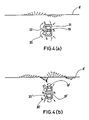
- Figure 3b shows a sectional view of a focus controller of the kind as disclosed in Japanese patent publication No. 57-113431. Symbols N and S respectively denote the north and south poles.
- the focus controller provides the magnetic space 16 available for the focussing operation in an area close to the optical disc. This construction minimises leakage magnetism that would otherwise adversely affect the recording medium 8' of the optical disc. The leakage magnetism will significantly affect the surface of the recording medium 8' of the optical disc if said magnetic space 16 for the focussing operation is provided in an area remote from the optical disc as shown in Figure 3b.
- the length of each arrow in Figures 3a and 3b respectively denotes the intensity of the leakage magnetism at the moment when the focussing operation has just started while the direction of the leakage magnetism is shown by the direction of the arrows.
- the tracking controller of Figure 4a provides the permanent magnet 19 available for the tracking operation in the centre of the closed magnetic circuit. This construction minimises leakage magnetism that would otherwise adversely affect the recording medium 8' of the optical disc. In a construction where the permanent magnet 19' available for the tracking operation is provided encircling the closed magnetic circuit, if the magnitude of the magnetic field that functions in the magnetic space 22' is designed to be equal to that in the magnetic space 22 of Figure 4a available for the tracking operation, the leakage magnetism will significantly affect the surface of the recording medium 8' of the optical disc.
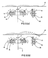
- Figure 5a shows sectional views of both the focussing and tracking controllers in a combination incorporating improvements in accordance with the present invention
- Figure 5b shows sectional views of both the focussing and tracking controllers in a combination which does not incorporate such improvements.
- both the focussing and tracking controllers with the improved means are set in positions close to each other, and the magnetic poles of the focussing yoke plate 14 and of the tracking yoke 21 which are the portions of the closed magnetic circuits of the focussing and tracking controllers which are both closest to each other and disposed to be closest to the disc, are of the same polarity i.e., poles N and N face each other, as shown in Figure 5a.
- the example shown in Figure 5b illustrates that the magnetic poles of the focussing and tracking controllers which do not incorporate the Fig 5a improvement are set in positions close to each other, but the magnetic poles of the focussing yoke plate 14 which is set close to the optical disc, and the tracking yoke 21 are of the opposite polarity, i.e., poles N and S face each other.
- the magnitude of the leakage magnetism adversely affecting the surface of the recording medium 8' of the optical disc is double the leakage magnetism in the device shown in Figure 5a.
- any adverse effect of the leakage magnetism on the surface of the recording medium 8' of the optical disc can be reduced further by additionally providing the following means including (a) a construction that provides a highly permeable magnetic substance such as permalloy in a position facing the optical disc of the optical focus position control device, (b) a construction that includes the entire optical focus position control device in said highly permeable magnetic substance, (c) a construction that includes a holder made of said highly permeable magnetic substance for supporting the entire optical focus position control device, and (d) a construction that includes both the focussing and tracking controllers within said highly permeable magnetic substance.
- Figure 6 shows a plan view of the optical focus position control device shown in Figure 2.
- an objective lens mirror cylinder 10 is provided in such a way that it can be moved only in the dual axes directions, i.e., either in the vertical (up/down) or horizontal (left/right) directions since it is supported by the vertically workable elastic material 12 that moves in the focussing direction and by the horizontally workable elastic material 26 that moves in the radial direction.
- This construction prevents the objective lens from even the slightest incline.
- a focussing drive coil 17 is provided in such a way that it can only move in the direction across the focussing magnetic space 16, while a radial drive coil 23 is provided so that it can only move in the direction across the tracking magnetic space 22.
- the magnetic space necessary for both the focussing and tracking operations can be extremely narrow, and so the electromagnetic force is used very effectively. This allows the size of the permanent magnet to be significantly reduced, and as a result, an extremely compact optical focus control device can be achieved.
- the focussing controller is driven by the electromagnetic effect which results from the interaction between the focussing closed magnetic circuit secured to the interim holder 11, and the focussing drive coil 17 secured to the objective lens mirror cylinder 10.
- Said interim holder 11 and the objective lens mirror cylinder 10 are connected to each other via elastic material that is moveable only in the vertical direction i.e. in the direction of focussing, for instance by parallel spring 12 that can be moved in the direction of focussing.
- the vertical movement of the objective lens mirror cylinder 10 will have a resonance frequency which is represented by the formula
- a driving force for the focussing operation is provided by the induced electromagnetic force
- the phase delay in the movement for a displacement X F of the objective lens mirror 10 in the focussing direction varies from 0° to 90° when 0 ⁇ f ⁇ f F , (where f (Hz) represents a frequency) whereas the delay will vary from 90° to 180° when f F ⁇ f, and it will be exactly 180° when f F ⁇ f.
- the movement phase delay for the displacement X F of the focus direction moving part can be adjusted to any desired level below 180°. This ensures very stable focus control operation.
- the tracking controller is driven by the electromagnetic effect that results from the interaction between the closed magnetic circuit secured to the stationary holder 27 and the tracking drive coil 23 on the tracking drive coil holder 24 which is secured to the interim holder 11.
- Said stationary holder 27 and the interim holder 11 are connected to each other by elastic material that is movable only to the left and to the right, i.e. in the radial direction, for instance by a parallel spring coupling 26 that moves in the direction of the disc radius.
- the weight of the focussing controller 18 is M T and the spring constant of the parallel spring 26 moving in the direction of the disc radius is K T , then the radial movement of the objective lens mirror cylinder 10 will have a resonance frequency (hereinafter called the primary resonance frequency) f T which is represented by the formula
- the interim holder 11 and the objective lens mirror cylinder 10 are connected to each other by the parallel spring coupling 12 which moves in the direction of focussing.
- this parallel spring 12 will move to the left and to the right to a certain extent due to its elasticity.
- the spring constant of the focus direction parallel spring 12 is K' F when it moves in a radial direction and it causes the objective lens mirror cylinder 10 to move to the left and right
- the spring will have a resonance frequency (hereinafter called the secondary resonance frequency) represented by
- K' F of the parallel spring that moves in the focussing direction is significantly large when the spring moves to the left and right, i.e. K' F >> K T .
- the secondary resonance frequency f' T is significantly higher than the primary resonance frequency f T , i.e. f' T >> f T .
- the movement phase delay in the displacement X T of the objective lens mirror cylinder 10 in the tracking direction varies from 0° to 90° when 0 ⁇ f ⁇ f T , or from 90° to 270° when f T ⁇ f ⁇ f' T , or from 270° to 360° when f' T ⁇ f.
- the phase delay in the movement in the displacement S T of the objective lens mirror cylinder 10 moving to the tracking target position Y T should remain below 180° throughout the frequency band of the tracking control signal.
- the phase advancing compensation circuit is used to advance the phase of the tracking drive signal F T , since there is a certain limit for advancing the phase amount, the phase cannot be compensated for in order that it can exceed 180° significantly.
- the second resonance frequency f' T should be at an optimum level above the frequency band of the tracking control signal.
- the frequency band used for the tracking control signal can vary, generally an optical disc apparatus uses frequencies within the range 1 to 4 KHz. Experiment has shown that consequently the secondary resonance frequency f' T should be set at a level of above 8KHz. Means for designing a construction that fully satisfies the above conditions are described below.
- the secondary resonance frequency f' T depends on the spring constant K' F of the parallel spring 12 when it moves to the left and right and on the weight M F of the parts which move in the focussing direction. Since there is a limit to the amount by which the weight of the objective lens 4 and the lens mirror cylinder 10 can be reduced, the weight M F of the part moving in the focussing direction cannot be decreased significantly. (Normally, said weight M F is in the range 0.5 to 10 grams). However, the greater the spring constant K' F , the greater the secondary resonance frequency f' T will be. The inventors followed up trials for increasing the spring constant K' F of the parallel spring 12 during its movement to the left and right.
- the spring constant K' F was found to be given by when the parallel spring 12 has a width X F and a thickness Y F .
- the spring constant K' F in the horizontal direction (left/right) can be increased by increasing the width X F and decreasing the thickness Y F of said parallel spring 12.
- the parallel spring 12 moving in the horizontal direction (left/right) should be designed so that it has a thickness of 20 to 50 microns and a width of 50 to 100 times the reference width Y F .
- the phase delay of the movement of displacement X T of the objective lens 4 relative to the tracking target position can be decreased below 180° within the frequency bands available for the tracking control signal. It is important that the phase advancing compensation circuit be used for correctly compensating for the movement phase delay.
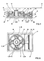
- FIG. 7 shows a sectional view of the optical focus position control device.
- damping material 28 is held in a space A between the objective lens mirror cylinder 10 and the focussing yoke 15, thus increasing the damping in the focussing direction.
- damping material 28 is held in a space B between the tracking drive coil holder 24 and the stationary holder 27, thus increasing the damping in the direction of the tracking.
- viscose-elastic materials such as silicon rubber, butyl rubber, silicon-butyl rubber, and acrylicethylene rubber, foaming synthetic resin such as foamed polyurethane, and viscose fluid such as silicon grease, can be used.
- Figure 8 shows a plan view of the optical focus position control device incorporating a second means of damping.
- Parallel spring 12 which moves in the direction of focus, has a structure that connects two concentric circles, whereby two flat sheet springs, each being connected to four arms at the edges, are provided one in each of the upper and lower positions (See Figure 2).
- Said parallel spring 12 moving in the direction of focus causes the objective lens mirror cylinder 10 to move only in the vertical direction relative to the position of the interim holder 11.
- Damping material 29 is bonded to the portions C of the surface of said parallel spring 12, where the largest amount of the relative displacement exists, thus resulting in greater damping characteristics in the direction of focus.
- viscoseelastic materials such as silicon-rubber, butyl rubber, silicon-butyl rubber, and acrylic-ethylene rubber, and foaming synthetic resin such as foamed polyurethane, can be used.
- Figure 9 shows a plan view of the optical focus position control device incorporating a third means of damping.
- Said damping material 29 is bonded to the portions C of the surface of the parallel spring 12, where the largest amount of the relative displacement exists.
- the damping material 29 is connected to the parallel spring 12 at the edges C1 and C2.
- Viscose fluid such as silicon grease is charged in the portion C3 located between the edges C1 and C2, thus increasing the damping characteristics in the direction of focus.
- Figure 10 shows a plan view of the optical focus position control device incorporating a fourth means of damping.
- the parallel springs 26 which move in the tracking direction are secured to the interim holder 11 (See Figure 2) at the centre, whilst also being secured to the stationary holder 27 at both ends. First, one end D is secured to the stationary holder 27, and then the other end E is inserted into a slit 30 of the stationary holder 27, and finally viscose fluid 31 such as silicon grease is charged into said slit 30 to complete the installation of each said parallel spring 26.
- the focussing and/or tracking means can be applied to any head positioning device for a recording disc, the head being used for recording, playing back or erasing information or for performing any combination of these functions.
Landscapes
- Optical Recording Or Reproduction (AREA)
Claims (14)
- Un dispositif optique de réglage de focalisation destiné à un appareil optique à disque qui enregistre, relit et/ou efface une information sur un milieu d'enregistrement (8) qui comprend une pellicule magnétique, en soumettant ladite pellicule magnétique à un faisceau optique, par exemple un faisceau laser (2), ledit dispositif optique de réglage de focalisation comprenant un appareillage de focalisation qui peut être mis en oeuvre pour déplacer la position du foyer optique du faisceau dans la direction de focalisation, c'est-à-dire dans une direction transversale à la pellicule, et un appareillage (19-24) de réglage de centrage qui peut être mis en oeuvre pour déplacer ladite position du foyer optique du faisceau dans la direction de centrage, c'est-à-dire dans une direction parallèle à la pellicule;
l'appareillage de réglage de focalisation incluant un moyen d'entraînement électromagnétique (13 - 17) de focalisation qui comprend :
un premier circuit magnétique fermé qui inclut un aimant permanent (13), une première plaque (14) de culasse, une culasse (15) et un espace magnétique (16) entre ladite première plaque (14) de culasse et la culasse (15), et;
une bobine d'entraînement (17) disposée pour se déplacer dans ledit espace magnétique;
et ledit appareillage de réglage de centrage incluant un moyen d'entraînement électromagnétique de centrage qui comprend :
un deuxième circuit magnétique fermé, indépendant du premier circuit magnétique fermé, qui inclut un aimant permanent (19), une deuxième plaque (20) de culasse, une culasse (21) et un espace magnétique (22) entre ladite deuxième plaque (20) de culasse et la culasse (21) et :
une bobine d'entraînement (23) agencée pour se déplacer dans ledit espace magnétique (22);
caractérisé en ce que des parties respectives (14, 21) du premier et du deuxième circuits magnétiques fermés des moyens d'entraînement électromagnétique de focalisation et de centrage, qui sont les deux les plus proches l'une de l'autre et sont disposées pour être les plus proches de la pellicule, sont de la même polarité magnétique. - Un dispositif optique de réglage de focalisation selon la revendication 1 dans lequel lesdites parties respectives sont des parties de la plaque (14) de culasse de l'appareillage de réglage de focalisation et de la culasse (21) de l'appareillage de réglage de centrage, respectivement.
- Un dispositif optique de réglage de focalisation selon la revendication 1 ou la revendication 2 dans lequel ledit appareillage de réglage de focalisation comprend un support intermédiaire (11) et est monté par rapport à un support stationnaire (27) à l'aide d'un premier couplage élastique parallèle (26) agencé pour permettre un déplacement de l'appareillage de réglage de focalisation par rapport au support stationnaire dans la direction de centrage,
ledit moyen d'entraînement électromagnétique de centrage étant couplé pour entraîner le support intermédiaire dans la direction de centrage par rapport au support stationnaire. - Un dispositif optique de réglage de focalisation selon la revendication 3, caractérisé en ce que ledit premier couplage élastique parallèle comprend une paire de ressorts parallèles comprenant chacun un élément métallique de ressort et du caoutchouc de latex attaché à la surface dudit élément métallique de ressort.
- Un dispositif optique de réglage de posiiton de foyer selon la revendication 4 dans lequel ledit caoutchouc de latex est un caoutchouc éthylène-acrylique de latex.
- Un dispositif optique de réglage de focalisation selon la revendication 5 dans lequel chaque élément métallique de ressort dudit premier couplage élastique parallèle est constitué d'un alliage résistant aux vibrations.
- Un dispositif optique de réglage de focalisation selon la revendication 3 caractérisé en ce que ledit premier couplage élastique parallèle comprend une paire de ressorts parallèles en un alliage résistant aux vibrations.
- Un dispositif optique de réglage de focalisation selon l'une quelconque des revendications 3 à 7 dans lequel est prévue une lentille (4) d'objectif au moyen de laquelle le faisceau optique est focalisé et un support cylindrique (10) dans lequel est montée la lentille d'objectif, ledit support cylindrique étant couplé au support intermédiaire (11) à l'aide d'un deuxième couplage élastique parallèle (12) agencé de manière à permettre un déplacement du support cylindrique par rapport au support intermédiaire dans la direction de focalisation, ledit moyen d'entraînement électromagnétique de focalisation étant couplé de manière à entraîner le support cylindrique dans la direction de focalisation par rapport au support intermédiaire.
- Un dispositif optique de réglage de focalisation selon la revendication 8 caractérisé en ce que ledit deuxième couplage élastique parallèle comprend une paire de ressorts parallèles comprenant chacun un élément métallique de ressort et du caoutchouc de latex attaché à la surface dudit élément métallique de ressort.
- Un dispositif optique de réglage de focalisation selon la revendication 9 dans lequel ledit caoutchouc de latex est un caoutchouc éthylène-acrylique de latex.
- Un dispositif optique de réglage de focalisation selon la revendication 9 ou la revendication 10 dans lequel chacun desdits éléments métalliques de ressort du deuxième couplage élastique parallèle est en un alliage résistant aux vibrations.
- Un dispositif optique de réglage de focalisation selon la revendication 8 caractérisé en ce que ledit deuxième couplage élastique parallèle comprend une paire de ressorts parallèles en un alliage résistant aux vibrations.
- Un dispositif optique de réglage de focalisation selon la revendication 3, comprenant en outre une matière élastique (29) liée audit premier couplage élastique parallèle pour améliorer les caractéristiques d'amortissement de celui-ci.
- Un dispositif optique de réglage de focalisation selon la revendication 8, comprenant en outre une matière élastique liée audit deuxième couplage élastique parallèle pour améliorer les caractéristiques d'amortissement de celui-ci.
Priority Applications (1)
| Application Number | Priority Date | Filing Date | Title |
|---|---|---|---|
| EP19880119199 EP0318772B1 (fr) | 1983-01-25 | 1983-09-15 | Dispositif de positionnement de la focalisation optique |
Applications Claiming Priority (7)
| Application Number | Priority Date | Filing Date | Title |
|---|---|---|---|
| JP1103783A JPS59139154A (ja) | 1983-01-25 | 1983-01-25 | 光集束位置制御装置 |
| JP11037/83 | 1983-01-25 | ||
| JP68770/83 | 1983-04-18 | ||
| JP6877083A JPS59193551A (ja) | 1983-04-18 | 1983-04-18 | 光集束位置制御装置 |
| JP6961983A JPS59195336A (ja) | 1983-04-19 | 1983-04-19 | 光集束位置制御装置 |
| JP69619/83 | 1983-04-19 | ||
| EP19880119199 EP0318772B1 (fr) | 1983-01-25 | 1983-09-15 | Dispositif de positionnement de la focalisation optique |
Related Parent Applications (2)
| Application Number | Title | Priority Date | Filing Date |
|---|---|---|---|
| EP83305435.6 Division | 1983-09-15 | ||
| EP83305435A Division-Into EP0115666B1 (fr) | 1983-01-25 | 1983-09-15 | Positionnement de la focalisation optique dans un appareil à disque optique |
Publications (2)
| Publication Number | Publication Date |
|---|---|
| EP0318772A1 EP0318772A1 (fr) | 1989-06-07 |
| EP0318772B1 true EP0318772B1 (fr) | 1992-06-10 |
Family
ID=27441471
Family Applications (1)
| Application Number | Title | Priority Date | Filing Date |
|---|---|---|---|
| EP19880119199 Expired EP0318772B1 (fr) | 1983-01-25 | 1983-09-15 | Dispositif de positionnement de la focalisation optique |
Country Status (1)
| Country | Link |
|---|---|
| EP (1) | EP0318772B1 (fr) |
Families Citing this family (1)
| Publication number | Priority date | Publication date | Assignee | Title |
|---|---|---|---|---|
| IT1248120B (it) * | 1991-01-25 | 1995-01-05 | Bruno Castellan | Gruppo traslatore-posizionatore strato |
Family Cites Families (3)
| Publication number | Priority date | Publication date | Assignee | Title |
|---|---|---|---|---|
| NL7920100A (nl) * | 1978-11-01 | 1981-02-27 | Hitachi Ltd | Inrichting voor het detecteren van magneto-optische anisotropie. |
| GB2060927B (en) * | 1979-07-24 | 1984-02-01 | Universal Pioneer Corp | Signal reading device for optical discs |
| US4437177A (en) * | 1979-11-12 | 1984-03-13 | Nippon Telegraph & Telephone Public Corporation | Small-sized video or audio pickup device having a beam deflector disposed within a focusing device support |
-
1983
- 1983-09-15 EP EP19880119199 patent/EP0318772B1/fr not_active Expired
Also Published As
| Publication number | Publication date |
|---|---|
| EP0318772A1 (fr) | 1989-06-07 |
Similar Documents
| Publication | Publication Date | Title |
|---|---|---|
| US4660190A (en) | Optical focus position control in optical disc apparatus | |
| EP0122816B1 (fr) | Positionnement de la focalisation optique dans un dispositif à mémoire optique | |
| JP3154141B2 (ja) | 緩衝装置及び緩衝装置を用いた円盤状記録媒体用の記録及び/又は再生装置 | |
| KR100378134B1 (ko) | 대물렌즈구동장치 | |
| EP0115666B1 (fr) | Positionnement de la focalisation optique dans un appareil à disque optique | |
| JPH04102232A (ja) | 対物レンズ駆動装置及び光ディスク装置 | |
| JPH08273177A (ja) | 光学系駆動装置 | |
| EP0333601A2 (fr) | Système de support et de positionnement d'une lentille d'objectif | |
| KR100362215B1 (ko) | (요크브릿지를이용하지않는)렌즈이동장치 | |
| EP0318772B1 (fr) | Dispositif de positionnement de la focalisation optique | |
| EP0314200B1 (fr) | Dispositif de positionnement de la focalisation | |
| CA1219073A (fr) | Commande de focalisation pour memoire optique | |
| US5901133A (en) | Objective lens actuator | |
| JPH06301995A (ja) | 情報記録及び/又は読取装置 | |
| JPS6243256B2 (fr) | ||
| JP2621200B2 (ja) | 対物レンズアクチュエータ | |
| JPS6284437A (ja) | 対物レンズ駆動装置 | |
| JPH0756696B2 (ja) | 光集束位置制御装置 | |
| JPH03154235A (ja) | アクチュエータ | |
| JPS63181133A (ja) | 対物レンズ駆動装置 | |
| JP2720557B2 (ja) | 対物レンズ駆動装置 | |
| JP2685840B2 (ja) | 対物レンズ駆動装置 | |
| JPS6289245A (ja) | 対物レンズ駆動装置 | |
| JPS6173248A (ja) | 光学的記録再生装置の対物レンズ駆動装置 | |
| JPS6127811B2 (fr) |
Legal Events
| Date | Code | Title | Description |
|---|---|---|---|
| PUAI | Public reference made under article 153(3) epc to a published international application that has entered the european phase |
Free format text: ORIGINAL CODE: 0009012 |
|
| AC | Divisional application: reference to earlier application |
Ref document number: 115666 Country of ref document: EP |
|
| AK | Designated contracting states |
Kind code of ref document: A1 Designated state(s): DE FR GB IT |
|
| 17P | Request for examination filed |
Effective date: 19890704 |
|
| 17Q | First examination report despatched |
Effective date: 19901018 |
|
| GRAA | (expected) grant |
Free format text: ORIGINAL CODE: 0009210 |
|
| AC | Divisional application: reference to earlier application |
Ref document number: 115666 Country of ref document: EP |
|
| AK | Designated contracting states |
Kind code of ref document: B1 Designated state(s): DE FR GB IT |
|
| ITF | It: translation for a ep patent filed | ||
| REF | Corresponds to: |
Ref document number: 3382580 Country of ref document: DE Date of ref document: 19920716 |
|
| ET | Fr: translation filed | ||
| PLBE | No opposition filed within time limit |
Free format text: ORIGINAL CODE: 0009261 |
|
| STAA | Information on the status of an ep patent application or granted ep patent |
Free format text: STATUS: NO OPPOSITION FILED WITHIN TIME LIMIT |
|
| 26N | No opposition filed | ||
| REG | Reference to a national code |
Ref country code: GB Ref legal event code: IF02 |
|
| PGFP | Annual fee paid to national office [announced via postgrant information from national office to epo] |
Ref country code: FR Payment date: 20020910 Year of fee payment: 20 |
|
| PGFP | Annual fee paid to national office [announced via postgrant information from national office to epo] |
Ref country code: GB Payment date: 20020911 Year of fee payment: 20 |
|
| PGFP | Annual fee paid to national office [announced via postgrant information from national office to epo] |
Ref country code: DE Payment date: 20020918 Year of fee payment: 20 |
|
| PG25 | Lapsed in a contracting state [announced via postgrant information from national office to epo] |
Ref country code: GB Free format text: LAPSE BECAUSE OF EXPIRATION OF PROTECTION Effective date: 20030914 |
|
| REG | Reference to a national code |
Ref country code: GB Ref legal event code: PE20 |