EP0319244A2 - Construction de tube à rayons X du type métal céramique refroidi par air - Google Patents
Construction de tube à rayons X du type métal céramique refroidi par air Download PDFInfo
- Publication number
- EP0319244A2 EP0319244A2 EP19880311291 EP88311291A EP0319244A2 EP 0319244 A2 EP0319244 A2 EP 0319244A2 EP 19880311291 EP19880311291 EP 19880311291 EP 88311291 A EP88311291 A EP 88311291A EP 0319244 A2 EP0319244 A2 EP 0319244A2
- Authority
- EP
- European Patent Office
- Prior art keywords
- ray tube
- shaft
- tube construction
- heat
- sleeve
- Prior art date
- Legal status (The legal status is an assumption and is not a legal conclusion. Google has not performed a legal analysis and makes no representation as to the accuracy of the status listed.)
- Granted
Links
- 238000010276 construction Methods 0.000 title claims abstract description 161
- 229910052751 metal Inorganic materials 0.000 title claims abstract description 35
- 239000002184 metal Substances 0.000 title claims abstract description 35
- 239000000919 ceramic Substances 0.000 title claims description 34
- 239000000463 material Substances 0.000 claims description 41
- 239000010935 stainless steel Substances 0.000 claims description 35
- 229910001220 stainless steel Inorganic materials 0.000 claims description 35
- 229910052802 copper Inorganic materials 0.000 claims description 30
- 239000010949 copper Substances 0.000 claims description 30
- RYGMFSIKBFXOCR-UHFFFAOYSA-N Copper Chemical compound [Cu] RYGMFSIKBFXOCR-UHFFFAOYSA-N 0.000 claims description 29
- 239000004020 conductor Substances 0.000 claims description 28
- 230000008878 coupling Effects 0.000 claims description 27
- 238000010168 coupling process Methods 0.000 claims description 27
- 238000005859 coupling reaction Methods 0.000 claims description 27
- PXHVJJICTQNCMI-UHFFFAOYSA-N Nickel Chemical compound [Ni] PXHVJJICTQNCMI-UHFFFAOYSA-N 0.000 claims description 22
- 239000011810 insulating material Substances 0.000 claims description 21
- 238000012546 transfer Methods 0.000 claims description 18
- 229910052790 beryllium Inorganic materials 0.000 claims description 15
- ATBAMAFKBVZNFJ-UHFFFAOYSA-N beryllium atom Chemical compound [Be] ATBAMAFKBVZNFJ-UHFFFAOYSA-N 0.000 claims description 15
- 241000555745 Sciuridae Species 0.000 claims description 13
- 229910052782 aluminium Inorganic materials 0.000 claims description 12
- XAGFODPZIPBFFR-UHFFFAOYSA-N aluminium Chemical compound [Al] XAGFODPZIPBFFR-UHFFFAOYSA-N 0.000 claims description 12
- 229910052759 nickel Inorganic materials 0.000 claims description 11
- 238000010894 electron beam technology Methods 0.000 claims description 10
- 229910000831 Steel Inorganic materials 0.000 claims description 9
- 238000000576 coating method Methods 0.000 claims description 9
- 239000010959 steel Substances 0.000 claims description 9
- 239000011248 coating agent Substances 0.000 claims description 8
- 229920002631 room-temperature vulcanizate silicone Polymers 0.000 claims description 8
- VYZAMTAEIAYCRO-UHFFFAOYSA-N Chromium Chemical compound [Cr] VYZAMTAEIAYCRO-UHFFFAOYSA-N 0.000 claims description 7
- 229910052804 chromium Inorganic materials 0.000 claims description 7
- 239000011651 chromium Substances 0.000 claims description 7
- 230000000694 effects Effects 0.000 claims description 7
- 229910000856 hastalloy Inorganic materials 0.000 claims description 6
- 239000010955 niobium Substances 0.000 claims description 5
- GUCVJGMIXFAOAE-UHFFFAOYSA-N niobium atom Chemical compound [Nb] GUCVJGMIXFAOAE-UHFFFAOYSA-N 0.000 claims description 5
- WGLPBDUCMAPZCE-UHFFFAOYSA-N Trioxochromium Chemical compound O=[Cr](=O)=O WGLPBDUCMAPZCE-UHFFFAOYSA-N 0.000 claims description 4
- 229910000423 chromium oxide Inorganic materials 0.000 claims description 4
- 239000004945 silicone rubber Substances 0.000 claims description 4
- 230000006378 damage Effects 0.000 claims description 3
- 239000004636 vulcanized rubber Substances 0.000 claims description 3
- 150000001875 compounds Chemical class 0.000 claims 1
- 210000003414 extremity Anatomy 0.000 description 21
- 238000005219 brazing Methods 0.000 description 19
- 238000001816 cooling Methods 0.000 description 17
- 239000003570 air Substances 0.000 description 16
- 230000008439 repair process Effects 0.000 description 10
- 229910000833 kovar Inorganic materials 0.000 description 8
- 230000005855 radiation Effects 0.000 description 8
- 229920001971 elastomer Polymers 0.000 description 7
- 238000003754 machining Methods 0.000 description 7
- 230000000717 retained effect Effects 0.000 description 7
- 210000003141 lower extremity Anatomy 0.000 description 6
- 239000003921 oil Substances 0.000 description 6
- 239000010453 quartz Substances 0.000 description 6
- VYPSYNLAJGMNEJ-UHFFFAOYSA-N silicon dioxide Inorganic materials O=[Si]=O VYPSYNLAJGMNEJ-UHFFFAOYSA-N 0.000 description 6
- 241000234295 Musa Species 0.000 description 5
- 235000018290 Musa x paradisiaca Nutrition 0.000 description 5
- 229920002379 silicone rubber Polymers 0.000 description 5
- UFHFLCQGNIYNRP-UHFFFAOYSA-N Hydrogen Chemical compound [H][H] UFHFLCQGNIYNRP-UHFFFAOYSA-N 0.000 description 4
- 239000011521 glass Substances 0.000 description 4
- 238000010438 heat treatment Methods 0.000 description 4
- 229910052739 hydrogen Inorganic materials 0.000 description 4
- 239000001257 hydrogen Substances 0.000 description 4
- 238000003466 welding Methods 0.000 description 4
- OKTJSMMVPCPJKN-UHFFFAOYSA-N Carbon Chemical compound [C] OKTJSMMVPCPJKN-UHFFFAOYSA-N 0.000 description 3
- 229910002804 graphite Inorganic materials 0.000 description 3
- 239000010439 graphite Substances 0.000 description 3
- 238000005338 heat storage Methods 0.000 description 3
- 238000009413 insulation Methods 0.000 description 3
- 238000000034 method Methods 0.000 description 3
- 238000007747 plating Methods 0.000 description 3
- DMFGNRRURHSENX-UHFFFAOYSA-N beryllium copper Chemical compound [Be].[Cu] DMFGNRRURHSENX-UHFFFAOYSA-N 0.000 description 2
- 238000005266 casting Methods 0.000 description 2
- 238000013461 design Methods 0.000 description 2
- QDOXWKRWXJOMAK-UHFFFAOYSA-N dichromium trioxide Chemical compound O=[Cr]O[Cr]=O QDOXWKRWXJOMAK-UHFFFAOYSA-N 0.000 description 2
- 238000007667 floating Methods 0.000 description 2
- 230000017525 heat dissipation Effects 0.000 description 2
- 238000003384 imaging method Methods 0.000 description 2
- 238000009607 mammography Methods 0.000 description 2
- 238000004519 manufacturing process Methods 0.000 description 2
- DECCZIUVGMLHKQ-UHFFFAOYSA-N rhenium tungsten Chemical compound [W].[Re] DECCZIUVGMLHKQ-UHFFFAOYSA-N 0.000 description 2
- 239000007787 solid Substances 0.000 description 2
- 210000001364 upper extremity Anatomy 0.000 description 2
- 229910000881 Cu alloy Inorganic materials 0.000 description 1
- ZOKXTWBITQBERF-UHFFFAOYSA-N Molybdenum Chemical compound [Mo] ZOKXTWBITQBERF-UHFFFAOYSA-N 0.000 description 1
- 229910052581 Si3N4 Inorganic materials 0.000 description 1
- 238000010521 absorption reaction Methods 0.000 description 1
- 230000001133 acceleration Effects 0.000 description 1
- 239000012080 ambient air Substances 0.000 description 1
- 230000004888 barrier function Effects 0.000 description 1
- 238000005452 bending Methods 0.000 description 1
- 230000015572 biosynthetic process Effects 0.000 description 1
- 230000008859 change Effects 0.000 description 1
- ZTXONRUJVYXVTJ-UHFFFAOYSA-N chromium copper Chemical compound [Cr][Cu][Cr] ZTXONRUJVYXVTJ-UHFFFAOYSA-N 0.000 description 1
- 239000012459 cleaning agent Substances 0.000 description 1
- 238000004891 communication Methods 0.000 description 1
- 238000002591 computed tomography Methods 0.000 description 1
- 230000008602 contraction Effects 0.000 description 1
- 150000001879 copper Chemical class 0.000 description 1
- 238000005520 cutting process Methods 0.000 description 1
- 238000010292 electrical insulation Methods 0.000 description 1
- 229910001026 inconel Inorganic materials 0.000 description 1
- 238000010348 incorporation Methods 0.000 description 1
- 238000003780 insertion Methods 0.000 description 1
- 230000037431 insertion Effects 0.000 description 1
- 230000002452 interceptive effect Effects 0.000 description 1
- 238000005495 investment casting Methods 0.000 description 1
- 239000005355 lead glass Substances 0.000 description 1
- 239000000696 magnetic material Substances 0.000 description 1
- 229910052750 molybdenum Inorganic materials 0.000 description 1
- 239000011733 molybdenum Substances 0.000 description 1
- 230000003647 oxidation Effects 0.000 description 1
- 238000007254 oxidation reaction Methods 0.000 description 1
- 239000004033 plastic Substances 0.000 description 1
- 229920003023 plastic Polymers 0.000 description 1
- 238000002360 preparation method Methods 0.000 description 1
- 230000008569 process Effects 0.000 description 1
- 230000000644 propagated effect Effects 0.000 description 1
- 230000009467 reduction Effects 0.000 description 1
- 229910052702 rhenium Inorganic materials 0.000 description 1
- WUAPFZMCVAUBPE-UHFFFAOYSA-N rhenium atom Chemical compound [Re] WUAPFZMCVAUBPE-UHFFFAOYSA-N 0.000 description 1
- HQVNEWCFYHHQES-UHFFFAOYSA-N silicon nitride Chemical compound N12[Si]34N5[Si]62N3[Si]51N64 HQVNEWCFYHHQES-UHFFFAOYSA-N 0.000 description 1
- 229910052709 silver Inorganic materials 0.000 description 1
- 239000004332 silver Substances 0.000 description 1
- 238000005476 soldering Methods 0.000 description 1
- 125000006850 spacer group Chemical group 0.000 description 1
- 230000001629 suppression Effects 0.000 description 1
- 238000002207 thermal evaporation Methods 0.000 description 1
- WFKWXMTUELFFGS-UHFFFAOYSA-N tungsten Chemical compound [W] WFKWXMTUELFFGS-UHFFFAOYSA-N 0.000 description 1
- 229910052721 tungsten Inorganic materials 0.000 description 1
- 239000010937 tungsten Substances 0.000 description 1
- 125000000391 vinyl group Chemical group [H]C([*])=C([H])[H] 0.000 description 1
- 229920002554 vinyl polymer Polymers 0.000 description 1
- 238000004073 vulcanization Methods 0.000 description 1
- 238000004804 winding Methods 0.000 description 1
Images





Classifications
-
- H—ELECTRICITY
- H01—ELECTRIC ELEMENTS
- H01J—ELECTRIC DISCHARGE TUBES OR DISCHARGE LAMPS
- H01J35/00—X-ray tubes
- H01J35/02—Details
- H01J35/16—Vessels; Containers; Shields associated therewith
-
- H—ELECTRICITY
- H01—ELECTRIC ELEMENTS
- H01J—ELECTRIC DISCHARGE TUBES OR DISCHARGE LAMPS
- H01J35/00—X-ray tubes
- H01J35/02—Details
- H01J35/04—Electrodes ; Mutual position thereof; Constructional adaptations therefor
- H01J35/08—Anodes; Anti cathodes
- H01J35/10—Rotary anodes; Arrangements for rotating anodes; Cooling rotary anodes
- H01J35/105—Cooling of rotating anodes, e.g. heat emitting layers or structures
- H01J35/107—Cooling of the bearing assemblies
-
- H—ELECTRICITY
- H05—ELECTRIC TECHNIQUES NOT OTHERWISE PROVIDED FOR
- H05G—X-RAY TECHNIQUE
- H05G1/00—X-ray apparatus involving X-ray tubes; Circuits therefor
- H05G1/02—Constructional details
- H05G1/025—Means for cooling the X-ray tube or the generator
-
- H—ELECTRICITY
- H01—ELECTRIC ELEMENTS
- H01J—ELECTRIC DISCHARGE TUBES OR DISCHARGE LAMPS
- H01J2235/00—X-ray tubes
- H01J2235/16—Vessels
- H01J2235/165—Shielding arrangements
- H01J2235/168—Shielding arrangements against charged particles
Definitions
- This invention relates to x-ray tubes and more particularly to air cooled metal ceramic x-ray tubes.
- both the anode and the cathode are vacuum sealed in a glass envelope. Electrons released by the hot cathode filament are accelerated toward the anode by a high voltage. These high energy electrons generate x-rays upon impact on the solid anode and at the same time generate copious amounts of heat.
- the tube is mounted in a housing to protect the environment from unwanted x-rays.
- the housing typically of a rotating anode x-ray tube is filled with oil to provide electrical insulation and also to absorb heat generated by the anode.
- Such conventional x-ray tubes have numerous disadvantages including high cost and relatively short lifetimes. The oil cooling utilized greatly increases the cost of insulation and also inhibits repair of the same. There is therefore a need for a new and improved x-ray tube construction which overcomes these disadvantages.
- Another object of the invention is to provide a construction of the above character which can be manufactured to high precision allowing the incorporation of double-ended bearings.
- Another object of the invention is to provide an x-ray tube construction of the above character in which a precise focal spot alignment can be obtained.
- Another object of the invention is to provide an x-ray tube construction of the above character in which arcing created by filament evaporation onto glass is eliminated.
- Another object of the invention is to provide an x-ray tube construction of the above character in which the back scattered electrons are absorbed by surrounding metal resulting in less off focus radiation and improved image contrast.
- Another object of the invention is to provide an x-ray tube construction of the above character in which the bearings are protected from heat dissipated from the anode.
- Another object of the invention is to provide an x-ray tube construction of the above character in which the feedthroughs and in particular the cathode feedthrough is protected from the anode heat.
- Another object of the invention is to provide an x-ray tube construction of the above character which can withstand higher temperatures than can be accommodated with glass tubes.
- Another object of the invention is to provide an x-ray tube construction of the above character in which greatly improved heat dissipating qualities have been incorporated into the tube.
- Another object of the invention is to provide an x-ray tube construction of the above character having an improved x-ray window construction.
- Another object of the invention is to provide an x-ray tube construction of the above character which includes improved cable terminations.
- Another object of the invention is to provide an x-ray tube construction of the above character in which the high voltage receptacles provided can accommodate various types of federal standard terminals.
- Another object of the invention is to provide an x-ray tube construction of the above character in which different types of high temperature shafts can be accommodated.
- Another object of the invention is to provide an x-ray tube construction of the above character which makes possible the use of heavier anodes with resulting higher heat storage capacity.
- Another object of the invention is to provide an x-ray tube construction of the above character in which a heat cage is provided which is thermally extended to the rear end of the tube to provide an efficient heat exchange with forced air cooling.
- Another object of the invention is to provide an x-ray tube construction of the above character in which heat dissipated from the anode is diverted to the exterior before reaching the extremities of the shaft.
- Another object of the invention is to provide an x-ray tube construction of the above character in which the shielding is in intimate contact with the aluminum housing and the stainless steel envelope to provide excellent heat transfer characteristics.
- Another object of the invention is to provide an x-ray tube construction of the above character in which replacement of the tube in the field can be readily accomplished.
- Another object of the invention is to provide an x-ray tube construction of the above character in which a ceramic coupling is provided between the shaft and the rotor permitting the rotor to operate at the same ground potential as the stator.
- Another object of the invention is to provide an x-ray tube construction of the above character in which intimate electromagnetic coupling is achieved between the rotor and the stator.
- Another object of the invention is to provide an x-ray tube construction of the above character in which the anode can be rapidly accelerated and decelerated.
- Another object of the invention is to provide an x-ray tube construction of the above character which can lend itself to compact lightweight applications such as for mobile systems, C-ARM and mammography.
- Another object of the invention is to provide an x-ray tube construction of the above character which permits a higher anode speed making possible reduced anode diameter without losing power capability and the requirements needed for mammography and other similar applications.
- Another object of the invention is to provide an x-ray tube construction of the above character which can provide multiple focal spots with three or four-pole federal standard terminals.
- Another object of the invention is to provide an x-ray tube construction of the above character in which high voltage receptacles are provided with inserts having pins therein which can be readily adjusted to accommodate either the three pole or four pole federal standard terminations.
- Another object of the invention is to provide an x-ray tube construction of the above character which is provided with a heat cage which has been formed utilizing an electron beam weld to establish good mechanical contact to facilitate the transfer of heat.
- Another object of the invention is to provide an x-ray tube of the above construction which has been assembled in such a manner so that there are compensating movements of the rotor shaft during operation of the x-ray tube so that the anode remains in a relatively stationary position with respect to the movement longitudinally of the axis of the shaft.
- Another object of the invention is to provide an x-ray tube construction of the above character in which the cooling fins are brazed directly to the heat cage.
- Another object of the invention is to provide an x-ray tube construction of the above character in which a heat choke is provided for protecting the rear bearing.
- Another object of the invention is to provide an x-ray tube construction of the above character in which a split squirrel cage motor is utilized.
- Another object of the invention is to provide an x-ray tube construction of the above character in which the squirrel cage rotor is comprised of magnetic steel segments encased in copper.
- Another object of the invention is to provide an x-ray tube construction of the above character in which the cathode feed through is offset from the high voltage terminals to minimize heating of the insulating material provided in and around the high voltage terminals.
- Another object of the invention is to provide an x-ray tube construction of the above character which can be readily repaired.
- the x-ray tube construction of the present invention is comprised of a housing with a metal tube envelope therein and a shaft.
- An anode plate is carried by the shaft.
- Bearings are disposed on opposite sides of the anode plate and rotatably mount the shaft in the envelope.
- a motor drive is coupled to the shaft for rotating the shaft and the anode plate carried thereby.
- a cathode is provided for supplying electrons which are accelerated by a high voltage to the anode plate for creating x-rays upon impingement with the anode plate.
- a heat cage is disposed in the housing and the envelope and surrounds the anode plate.
- X-ray shielding means is disposed within the housing between the envelope and the housing.
- Windows are provided in the shielding means, the metal envelope and in the heat cage to permit x-rays to pass therethrough.
- Particularly novel means is provided for dissipating the heat generated in the anode and for dissipating the same exterior of the housing prior to the heat passing to the opposite extremities of the shaft.
- Shaft constructions have been utilized which inhibit the travel of heat to the opposite ends of the shafts and thereby serving to protect the bearings rotatably supporting the shaft.
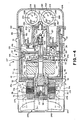
- the air cooled metal ceramic x-ray tube construction 21 consists of a cylindrical housing 22 formed of a suitable material such as aluminum.
- the cylindrical housing 22 can be formed as an investment casting.
- the housing 22 is closed at one end and open at the other end to provide a cylindrical interior recess 23 which is coated to facilitate the adherence of lead thereto.
- an electroless nickel plating is provided.
- the exterior of the cylindrical housing 22 is provided with a flat 24 on one side thereof which serves as a collimator support base.
- the opening 28 is basically in the fob of a rectangle which can be utilized for conventional x-ray imaging. It is also provided with sidewardly extending slots 29 disposed on two sides of the rectangular opening 28 to facilitate use with a 60° fan beam for CT scanning.
- the exterior surface of the cylindrical housing with the exception of the flat 24 is provided with longitudinally and radially extending fins 31 which are spaced circumferentially exterior of the cylindrical housing 22.
- the fins 31 serve as heat radiating fins.
- 36 of such fins can be provided around the outer circumference of the housing 22.
- the housing 22 on its extremities is provided with trunnion interfaces 32 and 33 which as is well known to those skilled in the art are utilized for mounting the x-ray tube in the apparatus in which the tube is to be utilized.
- the closed end portion 22a of the cylindrical housing is provided with a centrally disposed hole 34 extending through the same.
- the thinned wall portion can be provided by machining a rectangular recess on the exterior surface of the sleeve 43 to provide a thinned wall portion 43a of a suitable thickness such as approximately .005 inches.
- the base 42 closes the other end and is provided with a hole 44 which is in registration with the hole 34.
- a lead liner 46 is provided between the vacuum envelope 41 and the interior of the cylindrical housing 22. This lead envelope can be formed in a suitable manner such as by pouring molten lead into the space between the vacuum envelope 41 and the interior of the cylindrical housing 22.
- the lead liner 46 serves two purposes, first as a massive heat sink for the x-ray tube construction and second as a shield against stray radiation which may attempt to pass from within the tube. Because of the excellent bond formed between the lead liner and the aluminum housing 22, there is good heat transfer from the lead to the housing and the fins 31 carried by the housing. A window 47 is provided in the lead liner 46 which is in registration with the opening 28.
- a cylindrical heat cage 48 is provided within the interior of the vacuum envelope 41.
- This heat cage has one end seated in an annular recess 49 provided in the base 42 of the vacuum envelope 41 and is bonded therein by suitable means such as soldering or brazing.
- the lower extremity of the heat cage 48 is provided with a plurality of holes or openings 51 which are spaced circumferentially around the heat cage 48 and are provided to permit the escape of any cleaning agent which may be used during assembly and becomes entrapped between the cage 48 and the sleeve 43.
- the heat cage 48 is formed of a suitable material such as a chromium copper in which the chromium content is approximately 1% by weight.
- the copper is provided with a chromium content so that it is possible to cause an oxide of chromium to be formed on the exterior surface of the same during heating of the same in an atmosphere of wet hydrogen. It has been found that this oxidation process provides a greening of the exterior surface caused by the formation of a chromium oxide coating on the exterior surface of the heat cage. This coating provides an excellent heat emission surface which substantially enhances the heat dissipating capabilities of the heat cage 48.
- the heat cage 48 can be formed in a suitable manner such as by casting. Alternatively it can be formed from machined copper and chromium plated to provide a chromium oxide emissive coating.
- the heat cage 48 is provided with a window 53 which is in registration with the opening 28 provided in the cylindrical housing 22 through which the x-rays which are generated within the tube 21 can pass as hereinafter described.
- a curved plate 56 which is curved in one direction is formed of a suitable material such as beryllium.
- Beryllium is desirable because it has a low absorption coefficient for x-rays but provides protection for the stainless steel window portion 43a from damage by secondary electrons being emitted from within the tube 21.
- the plate 56 which serves as an x-ray window is held in place over the openings 28 and 53 by suitable means such as brazing it to the heat cage 48.
- the plate can be loosely held in a frame (not shown) secured between the sleeve 43 and the heat cage 48.
- the beryllium window can have a thickness of approximately 4 mils to protect a stainless steel wall 5 mils thick.
- a shaft assembly 61 is rotatably mounted within the cylindrical housing 22 and the envelope 41 and extends through the holes 44 and 34.
- the shaft assembly 61 consists of a shaft 62 formed of a suitable material which is capable of withstanding high temperatures. For example a material called Hastalloy or also identified as Haynes No. 230 can be used.
- the shaft 62 is hollow as shown and can be formed in a suitable manner such as by machining. It is provided with a thickened portion 62a which is intermediate the ends of the shaft. The thickened portion is provided with an annular seat 63 which abuts a shoulder 64.
- the shaft 62 is provided with relatively long thin-walled portions 62b and 62c on opposite ends of the thicker portion 62a.
- the portions 62b and 62c can have a suitable wall thickness as for example .020 to .025 inches. These thin-walled portions are provided to inhibit the travel of heat towards both extremities of the shaft.
- the Hastalloy material from which the shaft 62 is formed has a high percentage of chromium in it as for example in the range of approximately 32% by weight.
- the shaft is heated up to a suitable temperature as for example approximately 1,100°C in a wet hydrogen atmosphere to cause a chrome oxide coating to form on the shaft which has the greenish appearance. This oxide coating on the exterior of the shaft 62 provides excellent heat emission from the shaft.
- a solid ceramic coupling 66 is mounted on one end of the shaft 62. It is provided with metal Kovar collars 67 and 68 on opposite ends thereof.
- the metal collar 67 is secured to one end of the Hastalloy shaft 62 by suitable means such as brazing.
- the coupling 66 has a skirt portion 68 to enhance the voltage insulating capabilities of the part.
- the metal collar 68 at the other end of the coupling 66 is also secured by suitable means such as brazing to a cylindrical sleeve 71 of a suitable material such as stainless steel.
- the sleeve 71 serves as a rotor support and has a cylindrical squirrel cage rotor 72 mounted thereon and held in place by a circular plate or washer 73 formed of suitable material such as stainless steel.
- the plate 73 is secured to the rotor support sleeve 71 by suitable means such as screws 74.
- a drive pin 76 is carried by the outer extremity of the plate 73 and extends upwardly into the squirrel cage rotor 72.
- the squirrel cage rotor 72 is formed in a conventional manner as for example of alternating strips of copper and magnetic steel.
- the washer 73 can be utilized for balancing purposes for balancing one end of the shaft 62. This can be accomplished by removing the plate or washer 73 and shaving material from the same in appropriate locations to achieve the desired balance for the shaft assembly 61.
- Means is provided within the envelope 41 for mounting the shaft assembly 61 for rotatable movement within the envelope in a direction in which the axis of rotation extends longitudinally of the envelope 41.
- Such means is provided for mounting one end of the shaft carrying the rotor 72 and consists of a rear ball bearing assembly 81 (see Figure 5) having an outer race 82 which is mounted within and secured to the rotor support sleeve 71.
- the outer race 82 is adapted to rotate with the rotor support sleeve 71.
- the inner race 83 of the ball bearing assembly is held in a stationary position with respect to the envelope and is supported in such a manner so as to accommodate the expansion and retraction of the ball bearing assembly 81 during operation of the x-ray tube 21.
- a rotor housing 96 is provided for enclosing the rotor 72 within a vacuum-tight enclosure and also for providing support for the support plate 93 to prevent rotation of the same.
- This rotor housing 96 consists of a rotor sleeve 97 which has one end bonded in the hole 44 of the plate 42 by a suitable means such as brazing. The other end of the rotor sleeve 97 is closed off by rotor end plate 98 that is secured to the rotor sleeve 97 by suitable means such as brazing.
- the rotor sleeve 97 is provided with a thin wall portion 97a intermediate the ends of the same as for example having a thickness of approximately 12 mils to provide good magnetic coupling between the rotor and the stator.
- the support plate 93 is mounted in a fixed position within the rotor housing 96 by a suitable means such as a C-ring 98 seated in an annular recess 99 provided on the interior surface of the rotor sleeve 97. From the foregoing construction it can be seen that the interior of the rotor sleeve is in communication with the interior of the vacuum envelope 41.
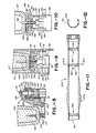
- Front bearing support means 101 (see Figure 8) is provided for mounting the other end of the shaft 62 and consists of a cylindrical cup-shaped front bearing housing 102 which is seated within the front extremity of the shaft 62.
- the outer race 103 of a front ball bearing assembly 104 is seated within the front bearing housing 102 for rotation therewith.
- the outer race 103 of the ball bearing assembly 104 is retained within the cup-shaped front bearing housing 102 by suitable means such as a C-ring 106.
- Yieldable spring means is provided in the form of a helical coil spring 107 formed of a suitable high temperature material such as stainless steel or Inconel which has one end engaging the front bearing housing 102 and has the other end engaging a washer 108.
- the washer 108 engages a push-rod pin 109 which is mounted in a push-rod 111.
- the push-rod 111 is slidably mounted in the front bearing housing 102 and has its rear distal extremity adapted to engage a push disc 112 slidably mounted within the shaft 62.
- the push disc 112 (see Figure 6) is provided with a dished recess 113 which is adapted to receive the rear end of the push-rod 111.
- the push disc 112 engages a clamping pin 116 which extends through elongated slots 117 provided in the shaft 62. The longer axes of the slots 117 extend in a direction axially of the shaft 62.
- the front ball bearing assembly 104 is provided with an inner race 131 (see Figure 8).
- a front bearing support member 132 is mounted in the inner race.
- a spacer 133 is mounted on the bearing support member 132 and engages the inner race 131.
- the bearing support member 132 also extends through a hole 134 provided in a bearing support bracket 136 and is retained in the hole 134 by a nut 137 threaded onto the front bearing support member 132 to retain the inner race of the ball bearing assembly in a stationary or non-rotatable position while retaining it in a fixed position within the tube envelope 41.
- the L-shaped bracket 136 is mounted upon a crossbar 139 formed of a suitable high temperature non-conducting insulating material such as silicon nitride.
- the bracket 136 is retained on the bar 139 by a spring clamp 141 secured to the bracket 136 by a suitable means such as a bolt 142.
- the bar 139 extends across the vacuum envelope 41 and is mounted upon a pair of support brackets (not shown) on opposite ends of the same which support the same on a circular cross plate 146.
- the brackets (not shown) which carry the bar 139 and the plate 146 are formed of a suitable metal such as stainless steel.
- the cross plate 146 overlies a cage cover plate 147 formed of the same copper material as the copper heat cage 48.
- the cover plate 147 overlies an annular flange 148 provided on the cage 48.
- Means is provided for establishing intimate contact between the cover plate 147 and the flange 148 of the cage 48 and includes a C-ring 151 seated in annular recess 152 in the cage 48.
- the C-ring 151 captures the outer circumferential surface of the cross plate 146.
- the cross plate 146 carries a plurality of screws 153 near its outer margin which are adapted to engage the cover plate 147. It can be seen by adjusting the screws 153 large forces can be provided on the cover plate 147 to form a n intimate contact with the flange 148 when the cross plate 146 is in engagement with the C-ring 151.
- the cover plate 147 and the cross plate 146 are provided with aligned openings 154 and 156 through which the shaft assembly 61 extends and on which the anode plate 121 is mounted. A major amount of the heat given off by the anode plate 121 is absorbed by the cross plates 146 and 147 to protect the front bearing assembly 104 from high heat. The heat from the cross plates 146 and 147 enters the heat cage 48 which dissipates the heat through the lead liner 46 and the finned cylindrical housing 22.
- a circular mounting ring 161 is mounted on the end of the sleeve 43 and is of greater thickness than sleeve 43.
- the mounting ring 161 is secured to the sleeve 43 by suitable means such as brazing.
- a circular terminal or top mounting plate 162 is mounted upon the mounting ring 161.
- the mounting ring 161 is formed of a suitable material such as stainless steel material hereinbefore described.
- the plate 162 is formed of a suitable material such as stainless steel also.
- a strip 163 of a suitable material such as stainless steel is welded to the plate 162 and to the mounting ring 163. When it is desired to remove this seal, this stainless steel ring 163 can be removed by machining and then the top cover plate 162 can be removed to facilitate the repair of the tube when necessary.
- a cup-shaped ceramic anode feedthrough 166 and a cup-shaped ceramic cathode feedthrough 167 are mounted in holes 168 and 169 provided in the cover plate 162.
- the feedthroughs 166 and 167 are of conventional construction and are provided with Kovar metal skirts 171 which are welded to the stainless steel cover plate 162 to provide vacuum-tight seals.
- the anode feedthrough 166 is provided with a single external female terminal 174 which receives an internal male banana-type plug 176 mounted within the feedthrough 166.
- the terminal 174 engages the metal spring clamp 141.
- the clamp 141 carries a coil spring 177 through which the terminal 174 extends.
- the spring 177 makes electrical contact with the plate 178 which is electrically connected to the terminal 174.
- the clamp 141 makes electrical contact to the anode shaft 62 through the bracket 196 and through the front ball bearing assembly 104.
- the cathode feedthrough 167 is provided with five female terminals with one central grid terminal 181 and one common terminal 182 and three filament terminals 183 disposed around the central terminal 181.
- Corresponding male banana-type plugs 184 are mounted internally of the feedthrough 167 in the female terminals 181, 182 and 183.
- a conventional cathode assembly 186 is provided which has three filaments 187. One end of each of the filaments 187 is connected to one of the filament terminals 183 and the other end is connected to the common terminal 182. One of the filaments 187 is shown in Figure 9.
- the cathode assembly 186 is carried by a pair of screws 188 (see Figure 10) which are threaded into the cathode assembly 186.
- the screws 188 are carried by a quartz disc 191 which is provided as a subassembly 192 and is mounted upon the terminals 181, 182 and 183 of the cathode feedthrough 167.
- Lock nuts 189 are provided on the screws 188 and serve to clamp the cathode assembly 186 onto the screws.
- Lock nuts 190 are also provided on these screws and serve to secure the screws to the quartz disc 191.
- This subassembly 192 can be supported in a suitable manner.
- a second quartz disc 193 is provided which is also mounted upon the terminals 181, 182 and 183 and engages a metal washer 194 mounted on the terminals and disposed between the disc 193 and the lower extremity of the cathode feedthrough 167.
- Additional washers 196 are mounted on the same terminals and serve to space the quartz disc 191 from disc 193.
- Spring-like contact elements 197 in the form of metallic strips of a suitable material such as nickel are provided.
- These strips 197 are provided with U-shaped extremities 197a which are secured to the outer extremities of the terminals 181, 182 and 183 by C-rings 198.
- Coil springs 199 are also mounted on the terminals 181, 182 and 183 between the U-shaped extremities 197a.
- Additional means is provided for insulating the cathode assembly from heat and consists of an outer sleeve 202 of stainless steel surrounding a quartz tube 203.
- the upper extremity of the stainless steel sleeve 202 is secured to the cover plate 162 by bringing it to the lower extremity of the skirt 171 of the cathode feedthrough 167.
- the sleeve 202 can be of suitable thickness such as .005 inch.
- the cathode assembly 186 extends through holes 206 and 207 provided in the plates 147 and 151. Electrons emitted from the filament 27 are directed onto the rhenium tungsten surface 132 to create x-rays which travel through the window 28.
- the cover plate 162 is provided with a pinch-off tube 211 which can be pinched off after the vacuum envelope 41 has been evacuated.
- a cover 212 is provided for covering the pinch-off tube 211.
- a viewing window (not shown) is also provided in the cover plate 212.
- a termination is provided for the x-ray tube which conforms to present federal termination standards for x-ray tubes.
- an end cap 216 formed of a suitable material such as lead which seats over one extremity of the cylindrical housing 22.
- the end cap 216 is provided with a planar surface 217 in which two receptacles 218 and 219 are provided of a conventional type.
- the space within end cap 216 not required for the receptacles 218 and 219 and the space within the anode and cathode feedthroughs 166 and 167 can be filled with a suitable insulating material 221 such as an RTV silicon rubber.
- Cables 222 and 223 with appropriate terminations are mounted in the receptacles 218 and 219.
- the cables 222 and 223 are adapted to be connected to a suitable high voltage source.
- Suitable means is provided for securing the end cap 216 to the cylindrical housing 22 to ensure that there is no leakage of x-rays from within the tube.
- Such means consists of hook-like elements 226 formed of stainless steel having one hooklike portion 226a secured to the plate 162 and which extend outwardly between the interior of the lower extremity of the end cap 216 and the exterior of the cylindrical housing 22.
- the hook-like elements 226 also have hook-like portions 226b which are connected to hook-like portions 227a of yieldable means in the form of springs 227 which extend longitudinally of the cylindrical housing between the fins 31 (see Figure 1). Hook-like elements 227b provided on the other ends of the springs 227 are secured to the other end of the housing 22 by connection to the trunnion interface 32.
- FIGS 11 and 12 there is shown a modified shaft 279 corresponding to the shaft 62 hereinbefore described.
- the shaft 279 differs from the shaft 62 in that it is provided with a plurality of rectangular slots 281 arranged in pairs or two spaced apart parallel rows with the slots in one row overlapping the slots in the other row.
- the major axis of each of the slots extends in a direction perpendicular to the longitudinal axis of the shaft 62a.
- One or more pairs of rows of slots can be provided on the shaft on opposite ends of the shaft 279 and spaced away from the thicker walled portion 279a.
- the slots 281 serve to inhibit heat transfer longitudinally of the shaft by providing less mass for the heat to travel through and also by providing a staggered circuitous path for heat to flow through the pairs of rows.
- the bushings 389 are removed and the syringe 372 is separated from the casing or mold 381.
- the heater 391 is removed and thereafter the split casing 381.
- the screws 384 are then removed as is the plate 383.
- another plate 396 formed of an insulating material is provided and banana type terminals 397 are threaded into the fittings 371 to hold the plate 396 in place to complete the terminal 361 with the cable 358.
- the cable 357 can be provided with a similar terminal 399.
- the terminal 399 can be inserted into the opening 354 in cap 351.
- the terminal 399 is bent through approximately 90° by being pushed through a curved passage 401 which has previously been formed within the end cap 351 by RTV silicon rubber 402 therein.
- the curved passage makes it possible to direct the cable terminal 399 so that the banana plug fitting 397 carried thereby can be pushed into the female receptacle carried by the feedthrough 166.
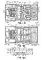
- a fan 423 is mounted within the housing 402 and is driven by a motor 424 to force air through and between the fins 421, with nickel or silver, for example, to provide cooling to the fins which serve to radiate heat from the heat sink or heat cage 403.
- the fins are directly brazed to the heat cage whereas in previous embodiments the fins formed a part of the housing.
- the heat cage 403 is supported within the housing 402 by a mounting ring 426 by suitable means such as brazing.
- the nuts 433 serve to retain the cross bar 428 in a fixed position to support the front bearing assembly 413 in a fixed position whereas the rear bearing assembly 414 is floating in the manner hereinbefore described for the previous embodiments in which the rear bearing assembly 414 serves as the floating bearing and is provided at the cold or cooler end of what can be characterized as the motor sub-assembly 436.
- the motor sub-assembly 436 is adapted to mate with a high voltage sub-assembly 437.
- the high voltage sub-assembly 437 consists of a circular plate 438 formed of a suitable material such as stainless steel.
- High voltage receptacles 441 and 442 are mounted in the plate 438.
- the top plate 438 is brazed to a cylindrical sleeve 446 formed of a suitable material such as stainless steel.
- the other extremity of the sleeve 446 is bonded to the copper cross lid 408 by suitable means such as brazing. The bonds which are formed between the sleeve 446 and the top plate 438 and with the cross lid 408 should be vacuum tight.
- An opening 457 of the same size as the recess 456 is provided in a lead liner or sleeve 458 which is formed in the manner hereinafter described which surrounds the cylindrical side wall 406 of the heat cage 403.
- the lead sleeve 458 is disposed between the housing 402 and the cylindrical side wall 406.
- the housing is provided with an opening 459 which is larger in size than the opening 457.
- a rectangular frame 461 formed of a suitable material such as stainless steel and having a suitable thickness such as .040 inches is brazed into the recess 453 and rests against the shoulder 454 by brazing the same to the copper side wall 406.
- the frame 461 carries a beryllium window 462 also having a suitable thickness, as for example, .040 inches and which also rests against the shoulder 454.
- the beryllium window 462 is secured to the frame 461 by brazing or loose slip fit into the frame 461.
- a thin sheet 464 of stainless steel 304 having a suitable thickness, as for example, .001 to .005 inches is also provided in the recess 453 and overlies the stainless steel frame 461 and the beryllium window 462. It is brazed to the frame 461 to form a vacuum tight seal between the side wall 406 and the opening 452. Brazing of all parts for the heat cage as fins 421 window construction 451 and rotor sleeve can be performed in one single brazing procedure.
- the lead sleeve or liner 458 surrounds the heat cage 403. It also surrounds the high voltage sub-assembly 437 and particularly the stainless steel sleeve 446 forming a part of the high voltage assembly.
- the lead sleeve liner 458 can be provided by utilizing the space between the housing 402 and the heat cage 403 and the sleeve 446 as a mold and then pouring molten lead which can have a temperature of approximately 350° C into this space and then permitting the molten lead to harden to provide the desired x-ray shielding for the tube.
- the stainless steel sleeve can be nickel plated.
- the copper heat cage 403 can be provided with a nickel plating, thus facilitating good heat transfer. The use of such surfaces with the lead promotes a solder-type interface which facilitates a conduction type transfer of heat to the housing 402.
- the window construction 451 has the same advantages of window constructions hereinbefore provided.
- the stainless steel wall or sheet 464 provides vacuum integrity for the tube whereas the rather thick .040 beryllium window avoids burnout of the stainless steel sheet 464 by substantially reducing the secondary electron bombardment without absorbing useful radiation.
- a pump stud 471 has been provided in the tube near the rear end of the tube as shown in Figure 21 and extends through the heat cage 403 and is provided for evacuating the tube envelope.
- the pump stud 471 is in the form of a copper tube which extends between the fins 421.
- the tube can be pinched off as shown and then can be pushed back so that it extends between two of the fins 421 and thus not interfering with the housing to be mounted around the x-ray tube.
- Each of the high voltage receptacles 441 and 442 is provided with a cup-shaped ceramic member 476 of the type hereinbefore described.
- a sleeve 477 is disposed within the ceramic member 476 but outside the tube vacuum and is formed of a suitable heat conductive material such as copper.
- the sleeve 477 extends substantially the entire length of the interior of the ceramic member 476. It can be provided with a portion 477a at the lower extremity which is thicker in cross section than the remainder of the sleeve to improve heat conduction along the sleeve.
- An insulating material 478 of a suitable type such as RTV is provided between the interior of the ceramic member 476 and the exterior of the copper sleeve 477.
- Each of the cathode and anode high voltage receptacle 441 and 442 is provided with five female terminals or receptacles 486 which are mounted in the ceramic member 441 and 442.
- Male plugs 487 of the banana plug type are disposed within the terminals or receptacles 486 outside the tube vacuum and are connected to conductors 488 which are connected to the federal standard terminal hereinafter described as a part of the tube.
- the terminals 486 of the anode high voltage receptacle 441 are connected by a spring loaded conductor 491 to the shaft 412 so that it applies a high voltage to the anode 411.
- the female receptacles or terminals 486 of the cathode high voltage receptacle 442 are connected by conductors 493 to a cathode assembly 496 of the type hereinbefore described.
- a cup-shaped corona suppression member 498 is provided around the female terminals 486. It is mounted on the ceramic member 476 by mounting posts 499. The member 498 also serve as a heat radiation barrier between interior tube components at high temperature and the RTV insulation provided in the terminal.
- the volume of the RTV is reduced this reduces the amount of contraction and expansion which must be accommodated which occurs with the heating and cooling of the RTV insulating material. This is important because the RTV insulating material has a relatively high coefficient of expansion so that it expands greatly upon the application of heat. Even though this expansion occurs, the effect is much less pronounced because the amount of RTV insulating material utilized is substantially reduced by the use of the copper sleeve 477.
- Lead shielding 509 is provided around the frontal portions of the sleeves 506 of the receptacles 501 and 502. Threaded rings 510 of stainless steel are embedded in the lead shielding 509 for receiving the federal standard terminations. This shielding augments the other lead shielding 503 provided with the interior of aluminum cover 504 for the x-ray tube which is similar to that hereinbefore described.
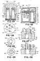
- FIG. 25 A slightly different arrangement for the receptacles 501 and 502 is shown in Figure 25 in which the receptacles 501 and 502 face in opposite directions to make maximum use of the space within the cover 504 and so that rear extremities of each of the receptacles overlies and is in line with the associated high voltage receptacle disposed at right angles thereto.
- the eccentric pins 521 and the pin central 522 can be formed of a suitable electrically conductive material such as beryllium copper.
- Each of the eccentric pins 521 is provided with a cylindrical body 523 which has a bore 524 provided therein which opens through the forward surface 526 of the cylindrical body.
- the bore 524 is offset in a lateral direction from the longitudinal axis of the cylindrical body 523 by a suitable distance such as .062 inches.
- a screwdriver slot 527 also extends through the surface 526 and extends diametrically of the cylindrical body 523.
- the cylindrical body 523 is provided with a cylindrical protrusion 528 which is axially aligned with the cylindrical body 523.
- the protrusion 528 is provided with a slot 529 extending diametrically therethrough and extending the length of the protrusion so that the protrusion is in the form of two parts 528a and 528b.
- a removable spring clip 531 formed of a suitable material such as beryllium copper is mounted on the protrusion 528.
- the clip 531 is provided with an extension 532 which is adapted to have one of the conductors 488 brazed or soldered thereto to form an electrical connection.
- the central pin 522 is provided with a cylindrical body 534 which has a centrally disposed bore 536 opening through the forward surface 537 thereof.
- the bore 536 is the same size as the bore 524 provided in the pin 521 and is adapted to receive a male plug of the banana type.
- the pin 522 is also provided with a cylindrical protrusion 538 which is formed integral with the cylindrical body 534.
- a slot 539 is formed therein extending diametrically thereof and extending the length thereof which serves to divide the cylindrical protrusion 538 into portions 538a and 538b.
- a spring clip 531 of the type hereinbefore described with the pin 521 is mounted on the protrusion 538 and is also adapted to be connected to one of the conductors 488.
- the use of the off-centered or eccentric pins 521 makes it very easy to accommodate either a three-pole or four-pole federal standard termination carrying male terminals.
- By rotating the pins 521 by the use of the screwdriver slots it is possible to position the three pins in the holes 513, 514, 516 and 517 so that the bores 524 are in alignment with a bolt circle of .687 inches to make it possible to mate with a federal standard three pole termination.
- the eccentric pins 521 By rotating the eccentric pins 521 to other positions, the pins provided in the holes 513, 514, 516 and 517 can be rotated so that the bores 524 therein are in alignment with a bolt circle of .812 inches which corresponds to the federal standard 4 pole termination.
- a conductor 541 which can be brazed or soldered to the appropriate terminals.
- a conductor 541 can be utilized for connecting the pins in the holes 512 and 516 which are carrying the pins for the terminals S1 and S2.
- the x-ray tube construction readily meets radiation safety requirements because the housing itself is shielded along its cylindrical surface and the receptacles 501 and 502 are shielded by a cast lead structure as shown in Figure 25. Also in order to minimize radiation escaping from the x-ray tube, a folded terminal arrangement is provided in which the high voltage receptacles 441 and 442 are disposed at right angles with respect to the receptacles 501 and 502.
- a cup-shaped member 546 is provided which surrounds the protrusions 528 on the pins 521 and the protrusions 538 on the pins 522.
- This cup-shaped member 546 is secured to the sleeve 477 and the sleeve 477 is connected to a clip 531 mounted on one of the protrusions 528 carried by the insert 511.
- the receptacles 501 and 502 are surrounded with a suitable insulating material such as the RTV silicone rubber.
- the aluminum housing 402 can be removed.
- the lead sleeve 458 can be cut and peeled off. This exposes the heat cage assembly comprised of the heat cage 403 and the cross plate 408 and the weld line 409.
- This heat cage can be opened up by machining a groove into the heat cage of a suitable width, as for example, approximately 1/8th of an inch making it possible to remove the cross lid 408 and giving access to the interior components.
- a ring of the same thickness as the material removed during the machining operation as for example 1/8th inch thickness and formed of the same material as the heat cage can be inserted between the top of the heat cage 403 and the cross plate 408.
- two electron beam welds can be provided to form the good mechanical seal between the parts as well as a good vacuum seal.
- the lead sheath and the exterior housing can then be replaced in the same manner as hereinbefore described in connection with the original fabrication of the x-ray tube.
- the x-ray tube construction shown in Figures 21 through 30 has numerous advantages which were pointed out in connection with the description of each of the several portions of the x-ray tube which are different from the previous embodiments.
- FIG 31 there is shown a partial cross sectional view of an x-ray tube construction which utilizes a double wall construction.
- the view which is shown in Figure 31 is the view showing the tube after it has been originally manufactured and then returned for repairs and reworked.
- the x-ray tube construction 561 shown in Figure 31 is comprised of a heat cage 562 formed of the same copper type material hereinbefore described which is provided with a bottom or end wall 563 and a cylindrical side wall 564. Fins 566 are brazed to the end wall 563.
- a mounting ring 568 is provided for mounting the heat cage 562.
- the mounting ring 568 is provided with an integral upstanding sleeve 569 also formed of stainless steel which is abutted against the lower extremity of the sleeve 572 along the line 571.
- the cylindrical sleeve 572 forms a part of a high voltage terminal assembly of the type hereinbefore described.
- the heat cage 562 is formed in such a manner so that when the sleeve 572 is mounted thereon, an annular space 573 at a suitable thickness as, for example, .040 inches is provided between the exterior surface of the side wall 564 and the interior surface of the sleeve 572.
- a ring 576 formed of a suitable material such as stainless steel of a suitable thickness as, for example, .005 inches is wrapped around the portion of the sleeves 569 and 572 and overlaps the line 571.
- This ring 576 is welded to the mounting ring 568 by a TIG weld along the line 577 and to the sleeve 572 along the weld line 578, providing a vacuum-tight bridge member over the joint 571 and to thereby seal off the tube.
- the x-ray tube construction also includes the lead sleeve 581 which can be formed in the manner hereinbefore described which is enclosed by the aluminum housing 582.
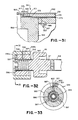
- FIG. 32 and 33 An alternative embodiment of a rear bearing support assembly 591 is shown in Figures 32 and 33.
- the shaft 412 is connected in a conventional manner to a ceramic coupling 66 by the use of a Kovar ring 67.
- the rear shaft support assembly 591 is provided with a rotor support 592.
- the rotor support 592 is bonded to a Kovar sleeve 593 which is bonded to the ceramic coupling 66.
- the outer race of the ball bearing assembly 81, rather than being directly mounted in the rotor support 592 is slipped into the sleeve 593 and the force of a helical spring 594 disposed within the sleeve 593.
- the segments are cast in a suitable conducting material such as copper or a copper alloy to provide copper segments 601 disposed on opposite sides of the magnetic steel segments.
- a suitable conducting material such as copper or a copper alloy to provide copper segments 601 disposed on opposite sides of the magnetic steel segments.
- FIG. 34 and 35 Still another embodiment of an x-ray tube construction incorporating the present invention is shown in Figures 34 and 35 in which an offset cathode assembly is provided.
- the cathode assembly has been in alignment with the high voltage receptacle for the cathode which in many cases has caused undue heating of the RTV of the high voltage receptacle.
- the arrangement shown in Figures 34 and 35 is utilized.
- a heat cage 602 is provided which has a cross plate 603 having an opening 604 therein in which there is disposed a cathode assembly 605 of the type hereinbefore described.
- the cathode assembly 605 is secured to the washer 611 in a suitable manner as for example by the use of standoff screws 612 which are threaded into the cathode assembly and which are adjusted in an appropriate position by having the screws 612 extend through the washer 611 and holding the cathode assembly in a desired position by nuts 613 threaded onto the screws on opposite sides of the washer 611.
- Conductors 616 are provided for making the connections from the cathode assembly 604 to the receptacle 442 as shown particularly in Figure 35.
- the heat generated by the cathode assembly 442 is spaced away from the high voltage receptacle 442 to thereby reduce the heat to which the high voltage receptacle 442 is subjected to. This helps to ensure that there will not be failures in the high voltage receptacle 442.
- the construction is such that when the tube is returned to the manufacturer many of the expensive parts thereof can be salvaged and used in remanufactured tubes.
- the construction of the tube is such that the anode and cathode feedthroughs are mounted to accommodate a long shaft so that one extremity of the shaft can extend therebetween.
Landscapes
- X-Ray Techniques (AREA)
Applications Claiming Priority (4)
| Application Number | Priority Date | Filing Date | Title |
|---|---|---|---|
| US07/126,842 US5056126A (en) | 1987-11-30 | 1987-11-30 | Air cooled metal ceramic x-ray tube construction |
| US07/273,553 US4964148A (en) | 1987-11-30 | 1988-11-21 | Air cooled metal ceramic x-ray tube construction |
| US126842 | 1993-09-20 | ||
| US273553 | 1994-07-11 |
Publications (3)
| Publication Number | Publication Date |
|---|---|
| EP0319244A2 true EP0319244A2 (fr) | 1989-06-07 |
| EP0319244A3 EP0319244A3 (en) | 1989-09-13 |
| EP0319244B1 EP0319244B1 (fr) | 1994-05-25 |
Family
ID=26825089
Family Applications (1)
| Application Number | Title | Priority Date | Filing Date |
|---|---|---|---|
| EP88311291A Expired - Lifetime EP0319244B1 (fr) | 1987-11-30 | 1988-11-29 | Construction de tube à rayons X du type métal céramique refroidi par air |
Country Status (5)
| Country | Link |
|---|---|
| US (1) | US4964148A (fr) |
| EP (1) | EP0319244B1 (fr) |
| JP (1) | JPH01272037A (fr) |
| CA (1) | CA1303116C (fr) |
| DE (1) | DE3889715T2 (fr) |
Cited By (20)
| Publication number | Priority date | Publication date | Assignee | Title |
|---|---|---|---|---|
| EP0768699A1 (fr) * | 1995-09-27 | 1997-04-16 | Kevex X-Ray Inc. | Tube à rayons X et élément barrière associé |
| WO1999012183A1 (fr) * | 1997-08-29 | 1999-03-11 | Varian Associates, Inc. | Appareil generateur de rayons x a boitier integre |
| FR2782836A1 (fr) * | 1998-08-25 | 2000-03-03 | Gen Electric | Tube a rayons x a enveloppe doublee de plomb et revetue d'un placage depose par electrolyse, cette enveloppe et son procede de fabrication |
| EP1321959A1 (fr) * | 2001-12-10 | 2003-06-25 | LEO Elektronenmikroskopie GmbH | Dispositif engendrant de la radiation ionizante |
| WO2003049138A3 (fr) * | 2001-12-04 | 2004-04-15 | X Ray Optical Sys Inc | Procede et dispositif de refroidissement et d'isolation electrique d'un composant haute tension generateur de chaleur tel qu'un tube a rayons x servant a analyser des courants fluidiques |
| EP1478007A1 (fr) * | 2003-05-13 | 2004-11-17 | GE Medical Systems Global Technology Company LLC | Assemblage de fixation d'une cible |
| EP1124249A3 (fr) * | 2000-02-10 | 2005-02-09 | Koninklijke Philips Electronics N.V. | Tube à rayons X avec palier de support |
| US7110506B2 (en) | 2001-12-04 | 2006-09-19 | X-Ray Optical Systems, Inc. | Method and device for cooling and electrically insulating a high-voltage, heat-generating component such as an x-ray tube for analyzing fluid streams |
| US9579714B1 (en) | 2015-12-17 | 2017-02-28 | General Electric Company | Method and assembly for forming components having internal passages using a lattice structure |
| US9968991B2 (en) | 2015-12-17 | 2018-05-15 | General Electric Company | Method and assembly for forming components having internal passages using a lattice structure |
| US9987677B2 (en) | 2015-12-17 | 2018-06-05 | General Electric Company | Method and assembly for forming components having internal passages using a jacketed core |
| US10046389B2 (en) | 2015-12-17 | 2018-08-14 | General Electric Company | Method and assembly for forming components having internal passages using a jacketed core |
| US10099283B2 (en) | 2015-12-17 | 2018-10-16 | General Electric Company | Method and assembly for forming components having an internal passage defined therein |
| US10099276B2 (en) | 2015-12-17 | 2018-10-16 | General Electric Company | Method and assembly for forming components having an internal passage defined therein |
| US10099284B2 (en) | 2015-12-17 | 2018-10-16 | General Electric Company | Method and assembly for forming components having a catalyzed internal passage defined therein |
| US10118217B2 (en) | 2015-12-17 | 2018-11-06 | General Electric Company | Method and assembly for forming components having internal passages using a jacketed core |
| US10137499B2 (en) | 2015-12-17 | 2018-11-27 | General Electric Company | Method and assembly for forming components having an internal passage defined therein |
| US10150158B2 (en) | 2015-12-17 | 2018-12-11 | General Electric Company | Method and assembly for forming components having internal passages using a jacketed core |
| US10286450B2 (en) | 2016-04-27 | 2019-05-14 | General Electric Company | Method and assembly for forming components using a jacketed core |
| US10335853B2 (en) | 2016-04-27 | 2019-07-02 | General Electric Company | Method and assembly for forming components using a jacketed core |
Families Citing this family (28)
| Publication number | Priority date | Publication date | Assignee | Title |
|---|---|---|---|---|
| US5185774A (en) * | 1990-11-23 | 1993-02-09 | Pxt Technology, Inc. | X-ray tube construction |
| FR2670299B1 (fr) * | 1990-12-07 | 1993-01-22 | Thomson Composants Militaires | Circuit integre avec controleur de test peripherique. |
| US5173931A (en) * | 1991-11-04 | 1992-12-22 | Norman Pond | High-intensity x-ray source with variable cooling |
| US6619842B1 (en) * | 1997-08-29 | 2003-09-16 | Varian Medical Systems, Inc. | X-ray tube and method of manufacture |
| US6064718A (en) * | 1998-09-29 | 2000-05-16 | The United States Of America As Represented By The Secretary Of The Navy | Field emission tube for a mobile X-ray unit |
| US6257762B1 (en) * | 1999-02-19 | 2001-07-10 | General Electric Company | Lead surface coating for an x-ray tube casing |
| US6282262B1 (en) * | 1999-11-10 | 2001-08-28 | Varian Medical Systems, Inc. | X-ray tube and method of manufacture |
| US6563908B1 (en) * | 1999-11-11 | 2003-05-13 | Kevex X-Ray, Inc. | High reliability high voltage device housing system |
| US6749337B1 (en) | 2000-01-26 | 2004-06-15 | Varian Medical Systems, Inc. | X-ray tube and method of manufacture |
| US7079624B1 (en) | 2000-01-26 | 2006-07-18 | Varian Medical Systems, Inc. | X-Ray tube and method of manufacture |
| JP2002124396A (ja) * | 2000-08-18 | 2002-04-26 | Marconi Medical Systems Inc | 解除可能な電気的結合装置及び方法 |
| AU2001296611A1 (en) * | 2000-10-23 | 2002-05-06 | Varian Medical Systems, Inc. | X-ray tube and method of manufacture |
| JP3898029B2 (ja) * | 2001-10-31 | 2007-03-28 | ジーイー・メディカル・システムズ・グローバル・テクノロジー・カンパニー・エルエルシー | X線発生装置 |
| JP3961262B2 (ja) * | 2001-10-31 | 2007-08-22 | ジーイー・メディカル・システムズ・グローバル・テクノロジー・カンパニー・エルエルシー | X線発生装置 |
| US7180981B2 (en) | 2002-04-08 | 2007-02-20 | Nanodynamics-88, Inc. | High quantum energy efficiency X-ray tube and targets |
| US7209546B1 (en) | 2002-04-15 | 2007-04-24 | Varian Medical Systems Technologies, Inc. | Apparatus and method for applying an absorptive coating to an x-ray tube |
| US6989486B2 (en) * | 2003-03-26 | 2006-01-24 | Xoft Microtube, Inc. | High voltage cable for a miniature x-ray tube |
| JP5106789B2 (ja) * | 2006-05-31 | 2012-12-26 | 株式会社日立メディコ | X線管装置及びx線ct装置 |
| US7376218B2 (en) * | 2006-08-16 | 2008-05-20 | Endicott Interconnect Technologies, Inc. | X-ray source assembly |
| EP2115438A4 (fr) | 2007-02-13 | 2013-12-04 | Sentinel Scanning Corp | Tomodensitométrie et detection de contrebande |
| JP5414167B2 (ja) * | 2007-11-02 | 2014-02-12 | 株式会社東芝 | X線管装置 |
| EP2438429A4 (fr) | 2009-06-05 | 2014-04-30 | Sentinel Scanning Corp | Système et procédé d'inspection d'un conteneur de transport |
| US8385505B2 (en) * | 2009-06-19 | 2013-02-26 | Varian Medical Systems, Inc. | X-ray tube bearing assembly |
| JP5322888B2 (ja) * | 2009-10-30 | 2013-10-23 | 株式会社東芝 | X線管 |
| JP6573380B2 (ja) * | 2015-07-27 | 2019-09-11 | キヤノン株式会社 | X線発生装置及びx線撮影システム |
| EP3419042A1 (fr) * | 2017-06-23 | 2018-12-26 | Koninklijke Philips N.V. | Isolateur de tube à rayons x |
| CN110168694A (zh) * | 2017-12-31 | 2019-08-23 | 上海联影医疗科技有限公司 | 辐射发射设备 |
| CN115702795A (zh) * | 2021-08-05 | 2023-02-17 | 通用电气精准医疗有限责任公司 | 悬吊装置以及x射线成像系统 |
Family Cites Families (18)
| Publication number | Priority date | Publication date | Assignee | Title |
|---|---|---|---|---|
| US1715151A (en) * | 1925-09-19 | 1929-05-28 | Westinghouse Lamp Co | Composite anode for x-ray tubes |
| US2090582A (en) * | 1934-02-09 | 1937-08-17 | Gen Electric X Ray Corp | X-ray tube |
| US2040156A (en) * | 1934-11-30 | 1936-05-12 | Westinghouse Lamp Co | Shockproof x-ray tube |
| US2121632A (en) * | 1936-05-11 | 1938-06-21 | Gen Electric X Ray Corp | X-ray tube |
| FR962793A (fr) * | 1942-08-17 | 1950-06-20 | ||
| DE2610660C3 (de) * | 1976-03-13 | 1979-02-22 | Philips Patentverwaltung Gmbh, 2000 Hamburg | Drehanoden-Röntgenröhre |
| US4187442A (en) * | 1978-09-05 | 1980-02-05 | General Electric Company | Rotating anode X-ray tube with improved thermal capacity |
| US4355410A (en) * | 1980-10-27 | 1982-10-19 | X-Ray Manufacturing & Supply, Inc. | Industrial X-ray machine |
| DE3107949A1 (de) * | 1981-03-02 | 1982-09-16 | Siemens AG, 1000 Berlin und 8000 München | Roentgenroehre |
| DK533882A (da) * | 1981-12-02 | 1983-06-03 | Litton Industrial Products | Roentgenroer |
| US4811375A (en) * | 1981-12-02 | 1989-03-07 | Medical Electronic Imaging Corporation | X-ray tubes |
| US4514204A (en) * | 1983-03-21 | 1985-04-30 | Air Products And Chemicals, Inc. | Bakeable cryopump |
| US4545064A (en) * | 1983-10-28 | 1985-10-01 | Litton Systems, Inc. | X-ray tube rotor mounting |
| US4577339A (en) * | 1983-10-28 | 1986-03-18 | Klostermann Heinrich F | Cable termination for x-ray tubes |
| EP0229192A1 (fr) * | 1985-07-11 | 1987-07-22 | Heinrich F. Klostermann | Fixation de rotor pour tube à rayons X |
| FR2566960B1 (fr) * | 1984-06-29 | 1986-11-14 | Thomson Cgr | Tube a rayons x a anode tournante et procede de fixation d'une anode tournante sur un axe support |
| US4674109A (en) * | 1984-09-29 | 1987-06-16 | Kabushiki Kaisha Toshiba | Rotating anode x-ray tube device |
| US4679220A (en) * | 1985-01-23 | 1987-07-07 | Kabushiki Kaisha Toshiba | X-ray tube device with a rotatable anode |
-
1988
- 1988-11-21 US US07/273,553 patent/US4964148A/en not_active Expired - Fee Related
- 1988-11-29 DE DE3889715T patent/DE3889715T2/de not_active Expired - Fee Related
- 1988-11-29 EP EP88311291A patent/EP0319244B1/fr not_active Expired - Lifetime
- 1988-11-29 CA CA000584467A patent/CA1303116C/fr not_active Expired - Lifetime
- 1988-11-30 JP JP63303863A patent/JPH01272037A/ja active Pending
Cited By (25)
| Publication number | Priority date | Publication date | Assignee | Title |
|---|---|---|---|---|
| EP0768699A1 (fr) * | 1995-09-27 | 1997-04-16 | Kevex X-Ray Inc. | Tube à rayons X et élément barrière associé |
| WO1999012183A1 (fr) * | 1997-08-29 | 1999-03-11 | Varian Associates, Inc. | Appareil generateur de rayons x a boitier integre |
| EP1475819A3 (fr) * | 1997-08-29 | 2005-02-09 | Varian Medical Systems Technologies, Inc. | Generateur de rayons x a boitier integre |
| FR2782836A1 (fr) * | 1998-08-25 | 2000-03-03 | Gen Electric | Tube a rayons x a enveloppe doublee de plomb et revetue d'un placage depose par electrolyse, cette enveloppe et son procede de fabrication |
| EP1124249A3 (fr) * | 2000-02-10 | 2005-02-09 | Koninklijke Philips Electronics N.V. | Tube à rayons X avec palier de support |
| WO2003049138A3 (fr) * | 2001-12-04 | 2004-04-15 | X Ray Optical Sys Inc | Procede et dispositif de refroidissement et d'isolation electrique d'un composant haute tension generateur de chaleur tel qu'un tube a rayons x servant a analyser des courants fluidiques |
| US7110506B2 (en) | 2001-12-04 | 2006-09-19 | X-Ray Optical Systems, Inc. | Method and device for cooling and electrically insulating a high-voltage, heat-generating component such as an x-ray tube for analyzing fluid streams |
| US7519159B2 (en) | 2001-12-04 | 2009-04-14 | X-Ray Optical Systems, Inc. | Method and device for cooling and electrically insulating a high voltage, heat-generating component such as an x-ray tube for analyzing fluid streams |
| EP1321959A1 (fr) * | 2001-12-10 | 2003-06-25 | LEO Elektronenmikroskopie GmbH | Dispositif engendrant de la radiation ionizante |
| US6787779B2 (en) | 2001-12-10 | 2004-09-07 | Leo Elektronenmikroskopie Gmbh | Apparatus wherein ionizing radiation is generated |
| EP1478007A1 (fr) * | 2003-05-13 | 2004-11-17 | GE Medical Systems Global Technology Company LLC | Assemblage de fixation d'une cible |
| US9968991B2 (en) | 2015-12-17 | 2018-05-15 | General Electric Company | Method and assembly for forming components having internal passages using a lattice structure |
| US10099284B2 (en) | 2015-12-17 | 2018-10-16 | General Electric Company | Method and assembly for forming components having a catalyzed internal passage defined therein |
| US9975176B2 (en) | 2015-12-17 | 2018-05-22 | General Electric Company | Method and assembly for forming components having internal passages using a lattice structure |
| US9987677B2 (en) | 2015-12-17 | 2018-06-05 | General Electric Company | Method and assembly for forming components having internal passages using a jacketed core |
| US10046389B2 (en) | 2015-12-17 | 2018-08-14 | General Electric Company | Method and assembly for forming components having internal passages using a jacketed core |
| US10099283B2 (en) | 2015-12-17 | 2018-10-16 | General Electric Company | Method and assembly for forming components having an internal passage defined therein |
| US10099276B2 (en) | 2015-12-17 | 2018-10-16 | General Electric Company | Method and assembly for forming components having an internal passage defined therein |
| US9579714B1 (en) | 2015-12-17 | 2017-02-28 | General Electric Company | Method and assembly for forming components having internal passages using a lattice structure |
| US10118217B2 (en) | 2015-12-17 | 2018-11-06 | General Electric Company | Method and assembly for forming components having internal passages using a jacketed core |
| US10137499B2 (en) | 2015-12-17 | 2018-11-27 | General Electric Company | Method and assembly for forming components having an internal passage defined therein |
| US10150158B2 (en) | 2015-12-17 | 2018-12-11 | General Electric Company | Method and assembly for forming components having internal passages using a jacketed core |
| US10286450B2 (en) | 2016-04-27 | 2019-05-14 | General Electric Company | Method and assembly for forming components using a jacketed core |
| US10335853B2 (en) | 2016-04-27 | 2019-07-02 | General Electric Company | Method and assembly for forming components using a jacketed core |
| US10981221B2 (en) | 2016-04-27 | 2021-04-20 | General Electric Company | Method and assembly for forming components using a jacketed core |
Also Published As
| Publication number | Publication date |
|---|---|
| JPH01272037A (ja) | 1989-10-31 |
| US4964148A (en) | 1990-10-16 |
| DE3889715D1 (de) | 1994-06-30 |
| EP0319244B1 (fr) | 1994-05-25 |
| DE3889715T2 (de) | 1994-12-01 |
| EP0319244A3 (en) | 1989-09-13 |
| CA1303116C (fr) | 1992-06-09 |
Similar Documents
| Publication | Publication Date | Title |
|---|---|---|
| US4964148A (en) | Air cooled metal ceramic x-ray tube construction | |
| US5056126A (en) | Air cooled metal ceramic x-ray tube construction | |
| US5802140A (en) | X-ray generating apparatus with integral housing | |
| US6215852B1 (en) | Thermal energy storage and transfer assembly | |
| JP5450916B2 (ja) | X線管 | |
| EP2495747B1 (fr) | Tube à rayons x | |
| US4884292A (en) | Air-cooled X-ray tube | |
| JP2001196019A (ja) | 一体的ハウジングを備える乳房撮影法用のx線管 | |
| US5515413A (en) | X-ray tube cathode cup assembly | |
| JPH1064460A (ja) | X線管 | |
| JPH04315752A (ja) | 高出力回転陽極x線管 | |
| US20070230663A1 (en) | X-ray tube | |
| JP4400782B2 (ja) | 単極ct管用の高熱伝導性のhvコネクタ | |
| US6362415B1 (en) | HV connector with heat transfer device for X-ray tube | |
| JP2001216928A (ja) | X線管 | |
| US5498185A (en) | Methods of making an improved X-ray tube cathode cup assembly | |
| US9728369B2 (en) | Two-part high voltage vacuum feed through for an electron tube | |
| US7142639B2 (en) | High voltage connector for x-ray tube | |
| JP2726252B2 (ja) | X線管 | |
| EP0768699B1 (fr) | Tube à rayons X et élément barrière associé | |
| JP2006302648A (ja) | 回転陽極x線管装置 | |
| GB2261765A (en) | Collector for a travelling-wave tube | |
| KR20220075093A (ko) | 절연필름을 구비한 고정장치를 갖는 회전양극형 x선관장치 | |
| JPH0864386A (ja) | 回転陽極x線管装置 | |
| JPH0785826A (ja) | X線管装置 |
Legal Events
| Date | Code | Title | Description |
|---|---|---|---|
| PUAI | Public reference made under article 153(3) epc to a published international application that has entered the european phase |
Free format text: ORIGINAL CODE: 0009012 |
|
| AK | Designated contracting states |
Kind code of ref document: A2 Designated state(s): DE FR GB |
|
| PUAL | Search report despatched |
Free format text: ORIGINAL CODE: 0009013 |
|
| AK | Designated contracting states |
Kind code of ref document: A3 Designated state(s): DE FR GB |
|
| 17P | Request for examination filed |
Effective date: 19900313 |
|
| RAP3 | Party data changed (applicant data changed or rights of an application transferred) |
Owner name: MEICOR, INC. |
|
| 17Q | First examination report despatched |
Effective date: 19921013 |
|
| 111Z | Information provided on other rights and legal means of execution |
Free format text: DE FR GB |
|
| RAP1 | Party data changed (applicant data changed or rights of an application transferred) |
Owner name: THERATRONICS INTERNATIONAL LIMITED |
|
| GRAA | (expected) grant |
Free format text: ORIGINAL CODE: 0009210 |
|
| AK | Designated contracting states |
Kind code of ref document: B1 Designated state(s): DE FR GB |
|
| REF | Corresponds to: |
Ref document number: 3889715 Country of ref document: DE Date of ref document: 19940630 |
|
| ET | Fr: translation filed | ||
| PGFP | Annual fee paid to national office [announced via postgrant information from national office to epo] |
Ref country code: GB Payment date: 19941111 Year of fee payment: 7 |
|
| PGFP | Annual fee paid to national office [announced via postgrant information from national office to epo] |
Ref country code: FR Payment date: 19941125 Year of fee payment: 7 |
|
| PGFP | Annual fee paid to national office [announced via postgrant information from national office to epo] |
Ref country code: DE Payment date: 19941129 Year of fee payment: 7 |
|
| PLBE | No opposition filed within time limit |
Free format text: ORIGINAL CODE: 0009261 |
|
| STAA | Information on the status of an ep patent application or granted ep patent |
Free format text: STATUS: NO OPPOSITION FILED WITHIN TIME LIMIT |
|
| 26N | No opposition filed | ||
| PG25 | Lapsed in a contracting state [announced via postgrant information from national office to epo] |
Ref country code: GB Effective date: 19951129 |
|
| GBPC | Gb: european patent ceased through non-payment of renewal fee |
Effective date: 19951129 |
|
| PG25 | Lapsed in a contracting state [announced via postgrant information from national office to epo] |
Ref country code: FR Effective date: 19960731 |
|
| PG25 | Lapsed in a contracting state [announced via postgrant information from national office to epo] |
Ref country code: DE Effective date: 19960801 |
|
| REG | Reference to a national code |
Ref country code: FR Ref legal event code: ST |