EP0321169A2 - Connecteur électrique rendant possible la prévention d'un couplage incomplet - Google Patents
Connecteur électrique rendant possible la prévention d'un couplage incomplet Download PDFInfo
- Publication number
- EP0321169A2 EP0321169A2 EP88311727A EP88311727A EP0321169A2 EP 0321169 A2 EP0321169 A2 EP 0321169A2 EP 88311727 A EP88311727 A EP 88311727A EP 88311727 A EP88311727 A EP 88311727A EP 0321169 A2 EP0321169 A2 EP 0321169A2
- Authority
- EP
- European Patent Office
- Prior art keywords
- connector
- path
- rib
- bodies
- bracket
- Prior art date
- Legal status (The legal status is an assumption and is not a legal conclusion. Google has not performed a legal analysis and makes no representation as to the accuracy of the status listed.)
- Granted
Links
Images



Classifications
-
- H—ELECTRICITY
- H01—ELECTRIC ELEMENTS
- H01R—ELECTRICALLY-CONDUCTIVE CONNECTIONS; STRUCTURAL ASSOCIATIONS OF A PLURALITY OF MUTUALLY-INSULATED ELECTRICAL CONNECTING ELEMENTS; COUPLING DEVICES; CURRENT COLLECTORS
- H01R13/00—Details of coupling devices of the kinds covered by groups H01R12/70 or H01R24/00 - H01R33/00
- H01R13/62—Means for facilitating engagement or disengagement of coupling parts or for holding them in engagement
- H01R13/639—Additional means for holding or locking coupling parts together, after engagement, e.g. separate keylock, retainer strap
-
- H—ELECTRICITY
- H01—ELECTRIC ELEMENTS
- H01R—ELECTRICALLY-CONDUCTIVE CONNECTIONS; STRUCTURAL ASSOCIATIONS OF A PLURALITY OF MUTUALLY-INSULATED ELECTRICAL CONNECTING ELEMENTS; COUPLING DEVICES; CURRENT COLLECTORS
- H01R13/00—Details of coupling devices of the kinds covered by groups H01R12/70 or H01R24/00 - H01R33/00
- H01R13/64—Means for preventing incorrect coupling
- H01R13/641—Means for preventing incorrect coupling by indicating incorrect coupling; by indicating correct or full engagement
-
- H—ELECTRICITY
- H01—ELECTRIC ELEMENTS
- H01R—ELECTRICALLY-CONDUCTIVE CONNECTIONS; STRUCTURAL ASSOCIATIONS OF A PLURALITY OF MUTUALLY-INSULATED ELECTRICAL CONNECTING ELEMENTS; COUPLING DEVICES; CURRENT COLLECTORS
- H01R13/00—Details of coupling devices of the kinds covered by groups H01R12/70 or H01R24/00 - H01R33/00
- H01R13/73—Means for mounting coupling parts to apparatus or structures, e.g. to a wall
Definitions
- the present invention relates to an electrical connector adapted to ensure complete coupling of associated connector bodies (hereinafter, referred to simply as electrical connector) for use in wire harnesses for automotive vehicles or the like.
- a male connector body and a female connector body are coupled and locked together to effect the mechanical connection of electrical terminals housed in the respective connector bodies. It has been conventional practice to confirm whether or not a connector is in locked engagement by manually sensing the state of engagement or listening to the snapping sound which is heard when the relevant connector bodies assume a locked state.
- the present invention was contrived with a view to solving the above-mentioned problems which are inherent to prior art connectors and relies upon detecting any incomplete coupling of male and female connector bodies during a process by means of which electrical connectors are fixed the body of an automotive vehicle or components therefor.
- the present invention provides an electrical connector comprising a male connector body and a female connector body which are coupled and locked together to complete the mechanical connection of electrical terminals housed in the respective connector bodies, wherein a path is formed in the male connector body in such a manner as to correspond to the shape and dimension of a bracket which can be used in fixing the connector to the body of an automotive vehicle or components thereof, and a rib is provided on the female connector body, the rib being adapted to traverse the path when the female connector body is coupled with the male one and to block a part of the path in the event that the connector bodies fail to engage properly.
- a fixing bracket is smoothly fitted in a path formed in the connector for that purpose when the male and female connector bodies thereof are in complete engagement since there is nothing blocking the path, thus allowing the connector to be fixed to the bracket.
- the connector cannot be mounted on the bracket since the path is blocked by the rib provided on the female connector body. Thus any worker can immediately detect the improper coupling of the connector bodies.
- the present invention provides another type of electrical connector comprising male and female connector bodies of the above-mentioned type wherein a support finger and a detection finger are provided on a bracket that is used in fixing the connector to the body of an automotive vehicle or components thereof, a path is formed in the male connector body in such a manner as to correspond to the shape and dimension of the support finger, a rib is provided on the rearward portion of the female connector body in such a manner as to bear against the detection finger when the two connector bodies are not in complete engagement, and the support finger is thus prevented from entering the path.
- the rib formed on the female connector body is adapted to bear against the detection finger when the male and female connector bodies thereof fail to assume a properly coupled condition, and the support finger is therefore prevented from entering the path.
- the detection finger slides over the back portion of the rib, and this allows the support finger to enter the path so as to support the connector.
- the detection finger engages the back portion of the rib, and disconnection of the connector is thus prevented.
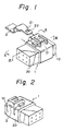
- FIGs. 1 and 2 are perspective views of an electrical connector 1 according to the present invention.
- This electrical connector is configured to complete the mechanical connection of electrical terminals (not shown) housed in the female and male connector bodies 10, 20 thereof by coupling and locking together those two connector bodies.
- the electrical connector 1 is fixed to the body of an automotive vehicle or a bracket 2 of one of the components thereof.
- Such fixing of the connector is attained by inserting a forward portion 21 of the bracket 2 into a path 3 formed on the electrical connector 1 after the connector 1 has been properly coupled in such a manner that a projection 31 provided inside the path 3 fits in a hole 22 formed in the forward portion 21 of the bracket 2.
- the path 3 is formed in such a manner as to correspond to the shape and dimension of the forward portion of the bracket 2.
- a rib 11 is provided at a predetermined position on the female connector body 10 in such a manner as to traverse the path 3 when the female connector body 10 is mated with the male connector body 20.
- the rib 11 is preferably formed on the connector body 10 at such a location that it passes through the path 3 when the two connector bodies 10, 20 are properly mated with each other (Fig. 4) and blocks a part of the path 3 when the same tow connector bodies 10, 20 are improperly mated (Fig. 5).
- the electrical connector 1 having a structure according to the present invention, since there is nothing blocking the path 3 formed on the connector 1 in which the bracket 2 is to be inserted when the female and male connector bodies 10, 20 are in a properly coupled condition (Fig. 4), the connector 1 is smoothly fitted over the bracket 2 so as to be fixed thereto.
- the rib 11 on the female connector body 10 blocks a part of the bracket insertion path 3 when the female and male connector bodies 10, 20 are in an improperly coupled condition (Fig. 5), the connector 1 cannot be mounted on the bracket 2. Thus, workers can immediately detect the improper coupling of the connector 1.
- Figs. 1 through 5 are also used to indicate components and/or portions similar to those in the relevant figures, and a detailed description of those components and/or portions will be omitted.
- the electrical connector 1 is fixed to the body of an automotive vehicle or a bracket 2 of one of the components thereof due to the same reason as that previously explained.
- a projection 31 provided inside the path 3 fits in a hole 22 formed in the support finger 21a of the bracket 2 and is locked in place, thus allowing the connector 1 to be fixed to the bracket 2.
- the path 3 is formed to correspond to the shape and dimension of the support finger 21a of the bracket 2.
- a detection finger 23 and a rib 11a are provided on the bracket 2 and the rearward portion of the female connector body 10, respectively.
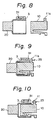
- This rib 11a is provided in such a location that it stays outside the path 3 when the female connector body 10 and the male connector body 20 are mated with each other, and the detection finger 23 stays on the back portion of the rib 11a in the event that the two connector bodies 10, 20 are properly mated with each other (Fig. 9).
- the rib 11a bears against the detection finger 23 of the bracket 2 (Fig. 11) in the event that both connector bodies 10, 20 are improperly coupled with each other (Fig. 10), entry of the support finger 21a into the path 3 thus being blocked.
- the rib 11a does not bear against the detection finger 23, in the event that the connector bodies 10, 20 are properly mated with each other (Fig. 9), and this allows the support finger 21a to smoothly enter the path 3 to support and fix the electrical connector 1 thereto.
- the detection finger 23 engages the back portion of the rib 11a, thus making it possible to ensure fixing of the connector 1 even more reliably.
- the present invention enables prevention of incomplete coupling of a connector, and this serves to eliminate the possibility of occurrence of electrical troubles in end products placed on the market.
- the present invention allows the connector to be fixed on the bracket, and this serves to ensure even stronger engagement of the male and female connector bodies.
Landscapes
- Details Of Connecting Devices For Male And Female Coupling (AREA)
- Connector Housings Or Holding Contact Members (AREA)
Applications Claiming Priority (4)
| Application Number | Priority Date | Filing Date | Title |
|---|---|---|---|
| JP190399/87 | 1987-12-15 | ||
| JP190398/87 | 1987-12-15 | ||
| JP19039987U JPH0715104Y2 (ja) | 1987-12-15 | 1987-12-15 | 半嵌合防止電気コネクタ |
| JP1987190398U JPH0737257Y2 (ja) | 1987-12-15 | 1987-12-15 | 半嵌合防止電気コネクタ |
Publications (3)
| Publication Number | Publication Date |
|---|---|
| EP0321169A2 true EP0321169A2 (fr) | 1989-06-21 |
| EP0321169A3 EP0321169A3 (en) | 1990-05-23 |
| EP0321169B1 EP0321169B1 (fr) | 1994-03-09 |
Family
ID=26506061
Family Applications (1)
| Application Number | Title | Priority Date | Filing Date |
|---|---|---|---|
| EP88311727A Expired - Lifetime EP0321169B1 (fr) | 1987-12-15 | 1988-12-12 | Connecteur électrique rendant possible la prévention d'un couplage incomplet |
Country Status (5)
| Country | Link |
|---|---|
| US (1) | US4892490A (fr) |
| EP (1) | EP0321169B1 (fr) |
| KR (1) | KR890011148A (fr) |
| DE (1) | DE3888322T2 (fr) |
| MY (1) | MY104356A (fr) |
Cited By (6)
| Publication number | Priority date | Publication date | Assignee | Title |
|---|---|---|---|---|
| US5174717A (en) * | 1991-06-10 | 1992-12-29 | Safeway Products Inc. | Cable harness and mounting hardware for propeller deicer |
| EP0484951A3 (en) * | 1990-11-08 | 1993-03-17 | Yazaki Corporation | Connector locking connection detection device |
| EP0666619A3 (fr) * | 1994-02-08 | 1997-07-16 | Sumitomo Wiring Systems | Connecteur électrique. |
| EP1530268A1 (fr) * | 2003-11-05 | 2005-05-11 | Delphi Technologies, Inc. | Boitier pour un connecteur electrique |
| EP0967692B1 (fr) * | 1998-06-26 | 2006-01-11 | Autonetworks Technologies, Ltd. | Connecteur et fixation pour connecteur |
| EP1650832A3 (fr) * | 2004-10-25 | 2007-05-02 | Yazaki Corporation | Boîtier de connexion électrique |
Families Citing this family (10)
| Publication number | Priority date | Publication date | Assignee | Title |
|---|---|---|---|---|
| US5217390A (en) * | 1990-04-16 | 1993-06-08 | Sumitomo Wiring Systems, Ltd. | Connector |
| JP2500721Y2 (ja) * | 1990-10-12 | 1996-06-12 | 矢崎総業株式会社 | 半嵌合防止コネクタ |
| US5324210A (en) * | 1993-01-29 | 1994-06-28 | Brickley Roger J | Latch mechanism |
| US5370550A (en) * | 1993-12-13 | 1994-12-06 | Osram Sylvania Inc. | Locking connector exhibiting audio-tactile didacticism |
| WO2008087947A1 (fr) * | 2007-01-19 | 2008-07-24 | Aisin Seiki Kabushiki Kaisha | Dispositif de transmission et dispositif de coulissement de siège à réglage électrique pour véhicule |
| KR101117968B1 (ko) * | 2009-11-05 | 2012-02-16 | 주식회사 경신 | 로킹장치 |
| US8926355B2 (en) | 2012-06-29 | 2015-01-06 | Lear Corporation | Connector position assurance device for a connector assembly |
| US8981961B2 (en) * | 2013-01-21 | 2015-03-17 | International Business Machines Corporation | Validation of mechanical connections |
| JP6774217B2 (ja) * | 2016-05-12 | 2020-10-21 | モレックス エルエルシー | コネクタ |
| US10355414B1 (en) | 2018-02-08 | 2019-07-16 | Delphi Technologies, Llc | Connector with a connector position assurance device |
Family Cites Families (4)
| Publication number | Priority date | Publication date | Assignee | Title |
|---|---|---|---|---|
| US3811104A (en) * | 1972-03-08 | 1974-05-14 | T Caldwell | Safety device for electrical outlets |
| US4746306A (en) * | 1982-03-26 | 1988-05-24 | General Motors Corporation | Electrical connector lock with gauge pin |
| US4634204A (en) * | 1985-12-24 | 1987-01-06 | General Motors Corporation | Electrical connector with connector position assurance/assist device |
| US4708413A (en) * | 1986-03-21 | 1987-11-24 | General Motors Corporation | Electrical connector with position assurance and assist |
-
1988
- 1988-12-10 KR KR1019880016425A patent/KR890011148A/ko not_active Withdrawn
- 1988-12-12 DE DE3888322T patent/DE3888322T2/de not_active Expired - Lifetime
- 1988-12-12 EP EP88311727A patent/EP0321169B1/fr not_active Expired - Lifetime
- 1988-12-14 US US07/284,114 patent/US4892490A/en not_active Expired - Lifetime
- 1988-12-14 MY MYPI88001447A patent/MY104356A/en unknown
Cited By (7)
| Publication number | Priority date | Publication date | Assignee | Title |
|---|---|---|---|---|
| EP0484951A3 (en) * | 1990-11-08 | 1993-03-17 | Yazaki Corporation | Connector locking connection detection device |
| AU656152B2 (en) * | 1990-11-08 | 1995-01-27 | Yazaki Corporation | Connector locking connection detection device |
| US5174717A (en) * | 1991-06-10 | 1992-12-29 | Safeway Products Inc. | Cable harness and mounting hardware for propeller deicer |
| EP0666619A3 (fr) * | 1994-02-08 | 1997-07-16 | Sumitomo Wiring Systems | Connecteur électrique. |
| EP0967692B1 (fr) * | 1998-06-26 | 2006-01-11 | Autonetworks Technologies, Ltd. | Connecteur et fixation pour connecteur |
| EP1530268A1 (fr) * | 2003-11-05 | 2005-05-11 | Delphi Technologies, Inc. | Boitier pour un connecteur electrique |
| EP1650832A3 (fr) * | 2004-10-25 | 2007-05-02 | Yazaki Corporation | Boîtier de connexion électrique |
Also Published As
| Publication number | Publication date |
|---|---|
| DE3888322D1 (de) | 1994-04-14 |
| EP0321169A3 (en) | 1990-05-23 |
| EP0321169B1 (fr) | 1994-03-09 |
| MY104356A (en) | 1994-03-31 |
| KR890011148A (ko) | 1989-08-12 |
| US4892490A (en) | 1990-01-09 |
| DE3888322T2 (de) | 1994-07-07 |
Similar Documents
| Publication | Publication Date | Title |
|---|---|---|
| EP0321169B1 (fr) | Connecteur électrique rendant possible la prévention d'un couplage incomplet | |
| JP2907377B2 (ja) | コネクタの結合検知装置 | |
| US5338211A (en) | Connector cover structure | |
| US4993967A (en) | Electric connector with a double locking mechanism | |
| KR100216002B1 (ko) | 단자의완전한삽입을용이하게하는단자위치확정장치를구비한전기커넥터 | |
| US6840789B2 (en) | Connector and a method of assembling it | |
| EP1158621B1 (fr) | Boítier de connecteur | |
| JP3002940B2 (ja) | レバー式コネクタ | |
| JPH087982A (ja) | ラッチ付き電気コネクタ | |
| US5707248A (en) | Device for preventing a wrong coupling of a connector | |
| JPH07307185A (ja) | コネクタのロック装置 | |
| US6241551B1 (en) | Divided-type connector | |
| JPH10172666A (ja) | 検知手段付き電気コネクタ | |
| JPH07307186A (ja) | 端子保護板を備えたコネクタ | |
| JPH1092499A (ja) | コネクタ | |
| EP0657968B1 (fr) | Connecteur à détection de verrouillage | |
| US5791935A (en) | Connector with a fitting-completion detector | |
| EP1701414B1 (fr) | Connecteur électrique | |
| JPH076809A (ja) | 端子係止具付きコネクタ | |
| US20230411892A1 (en) | Electrical connector assembly with flexible and rigid terminal locking features | |
| US7172459B2 (en) | Electrical connector housing, electrical connector, and connector assembly | |
| CA1306292C (fr) | Connecteur electrique permettant d'eviter les accouplements incomplets | |
| JPH10261464A (ja) | コネクタ装置 | |
| JPH11121080A (ja) | 合体式コネクタ | |
| US6478632B2 (en) | Shake preventing construction for a terminal fitting and a connector |
Legal Events
| Date | Code | Title | Description |
|---|---|---|---|
| PUAI | Public reference made under article 153(3) epc to a published international application that has entered the european phase |
Free format text: ORIGINAL CODE: 0009012 |
|
| AK | Designated contracting states |
Kind code of ref document: A2 Designated state(s): DE FR GB |
|
| PUAL | Search report despatched |
Free format text: ORIGINAL CODE: 0009013 |
|
| AK | Designated contracting states |
Kind code of ref document: A3 Designated state(s): DE FR GB |
|
| 17P | Request for examination filed |
Effective date: 19901112 |
|
| 17Q | First examination report despatched |
Effective date: 19920506 |
|
| GRAA | (expected) grant |
Free format text: ORIGINAL CODE: 0009210 |
|
| AK | Designated contracting states |
Kind code of ref document: B1 Designated state(s): DE FR GB |
|
| REF | Corresponds to: |
Ref document number: 3888322 Country of ref document: DE Date of ref document: 19940414 |
|
| ET | Fr: translation filed | ||
| PLBE | No opposition filed within time limit |
Free format text: ORIGINAL CODE: 0009261 |
|
| STAA | Information on the status of an ep patent application or granted ep patent |
Free format text: STATUS: NO OPPOSITION FILED WITHIN TIME LIMIT |
|
| 26N | No opposition filed | ||
| REG | Reference to a national code |
Ref country code: GB Ref legal event code: IF02 |
|
| PGFP | Annual fee paid to national office [announced via postgrant information from national office to epo] |
Ref country code: FR Payment date: 20031210 Year of fee payment: 16 |
|
| PG25 | Lapsed in a contracting state [announced via postgrant information from national office to epo] |
Ref country code: FR Free format text: LAPSE BECAUSE OF NON-PAYMENT OF DUE FEES Effective date: 20050831 |
|
| REG | Reference to a national code |
Ref country code: FR Ref legal event code: ST |
|
| PGFP | Annual fee paid to national office [announced via postgrant information from national office to epo] |
Ref country code: GB Payment date: 20071212 Year of fee payment: 20 |
|
| PGFP | Annual fee paid to national office [announced via postgrant information from national office to epo] |
Ref country code: DE Payment date: 20071206 Year of fee payment: 20 |
|
| REG | Reference to a national code |
Ref country code: GB Ref legal event code: PE20 Expiry date: 20081211 |
|
| PG25 | Lapsed in a contracting state [announced via postgrant information from national office to epo] |
Ref country code: GB Free format text: LAPSE BECAUSE OF EXPIRATION OF PROTECTION Effective date: 20081211 |