EP0322338A2 - Apparat zum Messen von hohen Temperaturen - Google Patents
Apparat zum Messen von hohen Temperaturen Download PDFInfo
- Publication number
- EP0322338A2 EP0322338A2 EP88630220A EP88630220A EP0322338A2 EP 0322338 A2 EP0322338 A2 EP 0322338A2 EP 88630220 A EP88630220 A EP 88630220A EP 88630220 A EP88630220 A EP 88630220A EP 0322338 A2 EP0322338 A2 EP 0322338A2
- Authority
- EP
- European Patent Office
- Prior art keywords
- temperature sensing
- sensing device
- ceramic member
- ceramic
- resistance means
- Prior art date
- Legal status (The legal status is an assumption and is not a legal conclusion. Google has not performed a legal analysis and makes no representation as to the accuracy of the status listed.)
- Ceased
Links
Images

Classifications
-
- G—PHYSICS
- G01—MEASURING; TESTING
- G01K—MEASURING TEMPERATURE; MEASURING QUANTITY OF HEAT; THERMALLY-SENSITIVE ELEMENTS NOT OTHERWISE PROVIDED FOR
- G01K7/00—Measuring temperature based on the use of electric or magnetic elements directly sensitive to heat ; Power supply therefor, e.g. using thermoelectric elements
- G01K7/16—Measuring temperature based on the use of electric or magnetic elements directly sensitive to heat ; Power supply therefor, e.g. using thermoelectric elements using resistive elements
- G01K7/18—Measuring temperature based on the use of electric or magnetic elements directly sensitive to heat ; Power supply therefor, e.g. using thermoelectric elements using resistive elements the element being a linear resistance, e.g. platinum resistance thermometer
Definitions
- This application relates to the art of temperature sensing and, more particularly, to sensing of very high temperatures.
- the invention is particularly applicable to apparatus used for sensing temperatures in ovens or the like, and will be described with particular reference thereto. However, it will be appreciated that the invention has broader aspects, and can be used for sensing temperatures in other environments.
- the temperature gradient between the opposite end portions of a temperature sensing probe is often very large. This large temperture gradient, and the extremely high temperatures at the sensing end of the probe, often cause failure of the probe or significantly reduce its life.
- a temperature sensing probe includes a pair of elongated spaced-apart electrically conductive strips fused along their entire length to a ceramic substrate.
- the conductive strips are connected at one end thereof to a platinum resistance thermometer element that is adhesively bonded to the ceramic substrate.
- the electrically conductive strips comprise a conductive thick film ceramic material that is deposited on the ceramic substrate and then fired for fusing same to the substrate.
- the conductive strips are connected with the platinum resistance thermometer by gold wires.
- the opposite or cooler end portions of the conductive strips, opposite from the platinum resistance thermometer chip, are connected to an electrical terminal with a conductive adhesive, such as conductive epoxy.
- the assembled ceramic substrate is inserted into a metal sheath to form a temperature probe.
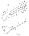
- Figure 1 shows a substantially flat and rectangular ceramic substrate A of alumina or the like.
- Substrate A has a substantially flat surface 10 extending along the entire length thereof.
- a pair of elongated spaced-apart conductive strips 12, 14 are provided on substrate surface 10.
- conductive strips 12, 14 are formed by laying down strips of a conductive ceramic glaze, and then firing same to fuse the glaze strips along their entire length to the substrate surface.
- conductive strips 12, 14 are conductive thick films. With both substrate A and condutive strips 12, 14 being of ceramic material and fused together, the coefficients of expansion of same are close enough that fractures in the conductive strips are unlikely.
- a platinum resistance thermometer chip or die B is attached to substrate surface 10 as by the use of a ceramic adhesive 16.
- Chip B defines a variable resistance means whose resistance varies with temperature.
- a platinum resistance circuit 18 is deposited on chip B in the form of a thin film as by sputtering, and is photolithographically shaped. Obviously, other types of sensing devices could be used.
- Gold wires 22, 24 are connected to conductive strips 12, 14, and to resistance circuit 18, by ultrasonic welding, by thermocompression welding (heat and pressure), or by thermosonic welding heat and ultrasonic power). This makes the high temperature end portion of the apparatus very reliable.
- the gold wires and ultrasonic welds define connecting means for connecting strips 12, 14 in electrically conductive relationship with resistance circuit 18.
- wires 18, 30 are connected with conventional wires 18, 30 by the use of a conductive adhesive, such as a conductive epoxy.
- Wires 28, 30 are attached to a suitable connector 34 for connecting the variable resistance means B to an electrical circuit.
- Ceramic substrate A is receivable in a protective metal sheath C to form a temperature probe.
- the diameter of sheath C is slightly greater than the width of ceramic substrate A so that the entire length of substrate A is receivable in sheath C down the center thereof.
- a suitable mounting bracket 36 is provided on sheath C for mounting same in a desired location with end portion 38 thereof positioned in the desired location for sensing the temperature of an environment.
- Variable resistance means B is located within sheath C adjacent end portion 38 thereof.
- substrate A being substantially flat and rectangular, it will be recognized that other shapes are also possible.
- substrate A could have a generally triangular cross-sectional shape, with surface 10 being one of the flat surfaces of the triangle.
- Conductive strips 12, 14 extend over a major portion of the length of ceramic substrate A, and variable resistance means B is mounted adjacent one end portion of substrate A.
- Gold wires 22, 24 provide a highly reliable connecting means for connecting variable resistance means to the conductive strips.
- Resistance circuit 18 is mounted on a ceramic die which in turn is adhesively bonded to substrate A.
- conductive strips 12, 14 may be laid down on substrate A as a thick film by use of a ceramic glaze conductive ink. The substrate and thick film strips are fired to fuse same together.
- the firing temperature may vary and, by way of example only, can be around 850° C.
- Resistance circuit 18 is provided on its ceramic die as by sputtering in a known manner to form a thin film.
- the die may be alumina or sapphire.
- Conductive ceramic glazes and adhesives are made by filling same with conductive metal particles.
- the variable resistance means may be connected in one leg of a wheatstone bridge for measuring the excitation current flowing through the resistant circuit.
- the temperature probe of the present application may be used to signal a solenoid for locking a door shut in a self-cleaning oven. The probe could also be used for turning a heating element off or for modulating same to maintain a desired temperature.
- the resistance of the conductive strips 12, 14 is small compared to the resistance of thermometer die B, and has a negligible effect on the temperature performance of die B.
- FIG. 3 shows generally U-shaped connector terminals D, E having spaced-apart legs 40, 42 and outwardly curved ends 44, 46. Terminals D, E are mounted in a connector body, within which wires are suitably connected to terminals D, E. This allows the cool end of the device to be directly inserted into terminals D, E. Legs 40, 42 resiliently grip substrate A, and frictionally engage strips 12, 14 in conductive relationship.
- FIG 4 shows a connector body F enclosing spaced-apart blades 50, 52 having outwardly curved outer end portions 54, 56 between which an entrance socket 60 is defined.
- the inner end portions of blades 50, 52 are turned inwardly and secured together in clamping relationship to wire 62 by fastener means 64.
- the spacing between blades 50, 52 is less than the thickness of substrate A and strips 12, 14 so that the substrate and strips are resiliently gripped between the blades.
Landscapes
- Physics & Mathematics (AREA)
- General Physics & Mathematics (AREA)
- Measuring Temperature Or Quantity Of Heat (AREA)
- Thermistors And Varistors (AREA)
- Resistance Heating (AREA)
Applications Claiming Priority (2)
| Application Number | Priority Date | Filing Date | Title |
|---|---|---|---|
| US07/134,881 US4841273A (en) | 1987-12-18 | 1987-12-18 | High temperature sensing apparatus |
| US134881 | 1987-12-18 |
Publications (2)
| Publication Number | Publication Date |
|---|---|
| EP0322338A2 true EP0322338A2 (de) | 1989-06-28 |
| EP0322338A3 EP0322338A3 (de) | 1990-07-11 |
Family
ID=22465435
Family Applications (1)
| Application Number | Title | Priority Date | Filing Date |
|---|---|---|---|
| EP88630220A Ceased EP0322338A3 (de) | 1987-12-18 | 1988-12-01 | Apparat zum Messen von hohen Temperaturen |
Country Status (4)
| Country | Link |
|---|---|
| US (1) | US4841273A (de) |
| EP (1) | EP0322338A3 (de) |
| JP (1) | JPH01200601A (de) |
| CA (1) | CA1314730C (de) |
Cited By (1)
| Publication number | Priority date | Publication date | Assignee | Title |
|---|---|---|---|---|
| FR2836205A1 (fr) * | 2002-02-15 | 2003-08-22 | Renault | Procede de determination de la temperature instantanee d'un gaz sous pression, notamment d'un gaz pour une pile a combustible |
Families Citing this family (11)
| Publication number | Priority date | Publication date | Assignee | Title |
|---|---|---|---|---|
| US5123752A (en) * | 1991-04-15 | 1992-06-23 | Eastman Kodak Company | Wear resistant temperature sensing device |
| DE19621000C2 (de) | 1996-05-24 | 1999-01-28 | Heraeus Sensor Nite Gmbh | Temperatur-Sensor mit einem Meßwiderstand |
| US5726624A (en) * | 1996-07-01 | 1998-03-10 | Honeywell Inc. | Temperature sensor with internal rigid substrate |
| US6354736B1 (en) * | 1999-03-24 | 2002-03-12 | Honeywell International Inc. | Wide temperature range RTD |
| US6341892B1 (en) * | 2000-02-03 | 2002-01-29 | George Schmermund | Resistance thermometer probe |
| EP1843138B1 (de) * | 2006-04-06 | 2012-05-16 | Sauer-Danfoss ApS | Schraube mit einer Schicht aus leitfähigem Material, das einen Sensor bildet |
| US20100033295A1 (en) | 2008-08-05 | 2010-02-11 | Therm-O-Disc, Incorporated | High temperature thermal cutoff device |
| DE102008036837A1 (de) * | 2008-08-07 | 2010-02-18 | Epcos Ag | Sensorvorrichtung und Verfahren zur Herstellung |
| US8228160B2 (en) * | 2008-11-14 | 2012-07-24 | Epcos Ag | Sensor element and process for assembling a sensor element |
| CN103515041B (zh) | 2012-06-15 | 2018-11-27 | 热敏碟公司 | 用于热截止装置的高热稳定性丸粒组合物及其制备方法和用途 |
| US10247619B2 (en) * | 2015-05-01 | 2019-04-02 | Vishay Measurements Group, Inc. | Resistance temperature detector with medium temperature coefficient and high linearity |
Family Cites Families (13)
| Publication number | Priority date | Publication date | Assignee | Title |
|---|---|---|---|---|
| US3537053A (en) * | 1966-01-19 | 1970-10-27 | Robertshaw Controls Co | Flexible temperature sensor for motor protection |
| CH510873A (de) * | 1969-07-08 | 1971-07-31 | Mettler Instrumente Ag | Elektrisches Widerstandsthermometer |
| US4007435A (en) * | 1973-07-30 | 1977-02-08 | Tien Tseng Ying | Sensor device and method of manufacturing same |
| US3952276A (en) * | 1974-02-21 | 1976-04-20 | Siemens Aktiengesellschaft | Fluid tight NTC high temperature sensor and method of producing same |
| CA997479A (en) * | 1974-07-22 | 1976-09-21 | Multi-State Devices Ltd. | Temperature sensitive resistor having a critical transition temperature of about 140.degree.c |
| US4139833A (en) * | 1976-11-22 | 1979-02-13 | Gould Inc. | Resistance temperature sensor |
| IT1100526B (it) * | 1977-12-05 | 1985-09-28 | Bendix Corp | Percettore della temperatura di un fluido |
| US4186368A (en) * | 1978-05-30 | 1980-01-29 | Tektronix, Inc. | Wide range, quick response temperature probe sensor |
| JPS5811724B2 (ja) * | 1979-06-14 | 1983-03-04 | 松下電器産業株式会社 | 高温用感温素子の製造方法 |
| US4419652A (en) * | 1981-10-09 | 1983-12-06 | Bendix Autolite Corp. | Temperature sensor |
| JPS6057903A (ja) * | 1983-09-09 | 1985-04-03 | 三井金属鉱業株式会社 | サ−ミスタ |
| JPH0638363B2 (ja) * | 1986-03-19 | 1994-05-18 | 松下電器産業株式会社 | 薄膜サ−ミスタ |
| CH673061A5 (en) * | 1987-07-13 | 1990-01-31 | Landis & Gyr Gmbh | Resistance thermometer with unstressed sensing element in housing - has annular grooves around sheath of cable end pressed into housing protecting element against bending stresses |
-
1987
- 1987-12-18 US US07/134,881 patent/US4841273A/en not_active Expired - Fee Related
-
1988
- 1988-09-12 CA CA000577119A patent/CA1314730C/en not_active Expired - Fee Related
- 1988-12-01 EP EP88630220A patent/EP0322338A3/de not_active Ceased
- 1988-12-15 JP JP63317579A patent/JPH01200601A/ja active Pending
Cited By (1)
| Publication number | Priority date | Publication date | Assignee | Title |
|---|---|---|---|---|
| FR2836205A1 (fr) * | 2002-02-15 | 2003-08-22 | Renault | Procede de determination de la temperature instantanee d'un gaz sous pression, notamment d'un gaz pour une pile a combustible |
Also Published As
| Publication number | Publication date |
|---|---|
| JPH01200601A (ja) | 1989-08-11 |
| CA1314730C (en) | 1993-03-23 |
| US4841273A (en) | 1989-06-20 |
| EP0322338A3 (de) | 1990-07-11 |
Similar Documents
| Publication | Publication Date | Title |
|---|---|---|
| EP0547750A1 (de) | Temperaturfühler | |
| US4841273A (en) | High temperature sensing apparatus | |
| CN100538920C (zh) | 具有钨/氮化铝的稳定高温传感器/加热器系统 | |
| US5720556A (en) | Temperature sensor probe | |
| US8166813B2 (en) | Temperature sensor and method for its manufacture | |
| CN102216747B (zh) | 传感器元件和用于组装传感器元件的工艺 | |
| GB1573235A (en) | Heated sensor for use on aircraft and a method of making such a sensor | |
| EP0171877A1 (de) | Verfahren zum Kontaktieren eines Thermistors an Anschlusselemente | |
| EP1119749A1 (de) | Oberflachentemperatursensor | |
| JPH07190863A (ja) | 温度センサ | |
| US4186368A (en) | Wide range, quick response temperature probe sensor | |
| US5057811A (en) | Electrothermal sensor | |
| US5142267A (en) | Level sensor which has high signal gain and can be used for fluids particularly chemically corrosive fluids | |
| JP2020523581A (ja) | 接触温度測定プローブ | |
| EP3724957B1 (de) | Dichtungsvorrichtung zum abdichten eines kaltendteils einer thermoelement-drahtanordnung auf der basis eines mineralisolierten kabels und einer thermoelement-temperaturerfassungsvorrichtung | |
| US4419652A (en) | Temperature sensor | |
| JP2004219123A (ja) | 測温用プローブ | |
| RU2145135C1 (ru) | Полупроводниковый термопреобразователь сопротивления | |
| JPH0774790B2 (ja) | 通電加熱法に用いられるセンサ− | |
| JP3555229B2 (ja) | 温度センサ | |
| EP0327252A2 (de) | Fixierung eines Widerstandstemperaturdetektors | |
| JPH0663804B2 (ja) | 質量流量センサ | |
| JPH0577737U (ja) | 薄膜測温抵抗体 | |
| US3497854A (en) | Electrothermal device | |
| JPH0328353Y2 (de) |
Legal Events
| Date | Code | Title | Description |
|---|---|---|---|
| PUAI | Public reference made under article 153(3) epc to a published international application that has entered the european phase |
Free format text: ORIGINAL CODE: 0009012 |
|
| AK | Designated contracting states |
Kind code of ref document: A2 Designated state(s): DE FR GB IT |
|
| PUAL | Search report despatched |
Free format text: ORIGINAL CODE: 0009013 |
|
| AK | Designated contracting states |
Kind code of ref document: A3 Designated state(s): DE FR GB IT |
|
| 17P | Request for examination filed |
Effective date: 19901227 |
|
| 17Q | First examination report despatched |
Effective date: 19920813 |
|
| STAA | Information on the status of an ep patent application or granted ep patent |
Free format text: STATUS: THE APPLICATION HAS BEEN REFUSED |
|
| 18R | Application refused |
Effective date: 19940221 |