EP0328482A2 - Outil rotatif en forme de disque pour le profilage de vis de meulage cylindriques pour la rectification de roues dentées - Google Patents
Outil rotatif en forme de disque pour le profilage de vis de meulage cylindriques pour la rectification de roues dentées Download PDFInfo
- Publication number
- EP0328482A2 EP0328482A2 EP89810049A EP89810049A EP0328482A2 EP 0328482 A2 EP0328482 A2 EP 0328482A2 EP 89810049 A EP89810049 A EP 89810049A EP 89810049 A EP89810049 A EP 89810049A EP 0328482 A2 EP0328482 A2 EP 0328482A2
- Authority
- EP
- European Patent Office
- Prior art keywords
- profiling
- grinding worm
- disc
- grinding
- flank
- Prior art date
- Legal status (The legal status is an assumption and is not a legal conclusion. Google has not performed a legal analysis and makes no representation as to the accuracy of the status listed.)
- Granted
Links
Images
Classifications
-
- B—PERFORMING OPERATIONS; TRANSPORTING
- B24—GRINDING; POLISHING
- B24B—MACHINES, DEVICES, OR PROCESSES FOR GRINDING OR POLISHING; DRESSING OR CONDITIONING OF ABRADING SURFACES; FEEDING OF GRINDING, POLISHING, OR LAPPING AGENTS
- B24B53/00—Devices or means for dressing or conditioning abrasive surfaces
- B24B53/06—Devices or means for dressing or conditioning abrasive surfaces of profiled abrasive wheels
- B24B53/075—Devices or means for dressing or conditioning abrasive surfaces of profiled abrasive wheels for workpieces having a grooved profile, e.g. gears, splined shafts, threads, worms
Definitions
- a precise, but slow and cumbersome process is to create the screw profile by means of ground shape diamonds. These are used in a similar way to turning steels and the procedure for this type of profiling can be compared to cutting a thread on a lathe. Because this process is slow and because the form diamond tools are very delicate and uneconomical, it is rarely used today.
- the profiling roller Similar and also known for a long time is the profiling roller, which is shaped according to the grinding worm profile and coated with hard material grains, but in contrast to the press roller is brought to high speed by a motor drive and thus produces the worm profile by an actual cutting process with relatively low forces.
- the disadvantage of this method is that the very high accuracy that must be required from the profiling roller can hardly be achieved.
- the hard body cannot be coated with the required quality.
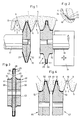
- the grinding worm 1 is used to profile a cylindrical grinding worm 1 for grinding spur gears in the continuous rolling process.
- the grinding worm 1 has a helical groove 2 with a first flank 3 for grinding one tooth flank, a second flank 4 for grinding the other tooth flank, and a foot section 5 and a head section 6.
- the foot section 5 consists of one each on the flanks 3, 4 About a convex edge 7 adjoining, radially directed sections 8, 9 and an approximately cylindrical section 10.
- the approximately cylindrical head section 6 merges on both sides with a curve and a convex edge 11 into the flanks 3, 4 (Fig. 2). When grinding the associated gear, the foot section 5 is not in engagement with the gear.
- the profiling tool consists of two rotationally symmetrical disks 15, 16, which are each clamped on a separate, motor-driven spindle 17, 18.
- the spindle 18 is on a cross slide 19 mounted and thus axially and radially adjustable relative to the spindle 17.
- the bearing of the spindle 17 and the cross slide 19, not shown, are mounted on a profiling slide, not shown, which moves to produce the helical groove 2 depending on the rotational movement of the grinding worm 1 back and forth parallel to the latter.
- the disk 15 is used for profiling the flanks 3, 4 and has an adapted surface 21, 22 for each.
- the surfaces 21, 22 are longer in axial section than the flanks 3, 4 and, when engaged with the grinding worm 1, project over the edges 7 , 11 out.
- the surfaces 21, 22 are covered with hard granules, e.g. with grains of diamond or cubic boron nitride. Because they have no sharp curvatures in the axial section, they can be lapped because the lapping disks can run out to the side, so that the flanks 3, 4 of the grinding worm 1 can be profiled with very high accuracy.
- the second disk 16 has a section 25 covered with hard material grains for profiling the foot section 5.
- the section 25 consists of two flat sections 26, 27 and a cylindrical section 28.
- the cylindrical section 28 alone would suffice; but it is advantageous to also cover pages 26, 27 for better edge retention.
- Both on the part 25, the disk 16 each has an approximately cylindrical part 31, 32 covered with hard material grains for profiling each about half of the head section 6.
- Each part 31, 32 merges into a conical portion 34 via a rounding 33, which is a little bit has a smaller opening angle than the flanks 3, 4 adjacent to the edge 11 (FIG. 2). Since the foot and head sections 5, 6 of the grinding worm 1 are not subject to high accuracy requirements, the parts 25, 31, 32 do not need to be lapped.
- the cross slide 19 aligns the second disk 16 with respect to the first disk 15 such that both the flanks 3, 4 and the foot and head sections 5, 6 are simultaneously profiled in the same pass.
- the profiling of the grinding worm 1 can thus be easily automated.
- the disk 15 can also be composed of two partial disks and a spacer.
- the disc can then be adapted to other widths of the groove 2 by changing the spacer.
- An analog solution is shown in Fig. 3 for the second disc 16 ', which is composed of three partial disks 38, 39, 40 and two spacers 41.
- the middle graduated disk 40 can, as indicated by dashed lines indicates a dividing plane 42 which is slightly inclined to the radial direction. The thickness of this indexing disk 40 can also be adjusted by means of inserts 43. Because of the inclined parting plane 42, the portion 28 forming the circumferential sections overlap when rotating the disc 16 '.
- the two disks 46, 47 are constructed identically and each have a hard-grain-coated surface 48, 49 for profiling the flanks 3, 4.
- the surface 48 for profiling the right flank 4 is closed on the outer circumference by a hard-grain-coated part 50 for profiling the left half of the Foot section 5, ie of section 8 and the adjoining half of section 10.
- the second disk 47 has a corresponding section 51 for profiling the other half of the foot section 5.
- the disks 46, 47 each have a section 52, 53 for processing half of the head sections 6 the two disks 46, 47 can be clamped on a common, driven spindle or, if an individual, small adjustment possibility of the two disks against one another is desired, can each be clamped on a separate, individually driven spindle.
- this disk it is indicated by dashed lines that this disk can also be constructed from a plurality of dividing disks and spacer disks.
Landscapes
- Engineering & Computer Science (AREA)
- Mechanical Engineering (AREA)
- Grinding-Machine Dressing And Accessory Apparatuses (AREA)
Applications Claiming Priority (2)
| Application Number | Priority Date | Filing Date | Title |
|---|---|---|---|
| CH52988 | 1988-02-12 | ||
| CH529/88 | 1988-02-12 |
Publications (3)
| Publication Number | Publication Date |
|---|---|
| EP0328482A2 true EP0328482A2 (fr) | 1989-08-16 |
| EP0328482A3 EP0328482A3 (fr) | 1991-03-27 |
| EP0328482B1 EP0328482B1 (fr) | 1993-07-14 |
Family
ID=4189093
Family Applications (1)
| Application Number | Title | Priority Date | Filing Date |
|---|---|---|---|
| EP89810049A Expired - Lifetime EP0328482B1 (fr) | 1988-02-12 | 1989-01-20 | Outil rotatif en forme de disque pour le profilage de vis de meulage cylindriques pour la rectification de roues dentées |
Country Status (4)
| Country | Link |
|---|---|
| US (1) | US4993194A (fr) |
| EP (1) | EP0328482B1 (fr) |
| JP (1) | JPH01246073A (fr) |
| DE (1) | DE58904886D1 (fr) |
Cited By (5)
| Publication number | Priority date | Publication date | Assignee | Title |
|---|---|---|---|---|
| WO1993019881A1 (fr) * | 1992-03-27 | 1993-10-14 | Niles Werkzeugmaschinen Gmbh Berlin | Procede et dispositif pour meuler les profils exterieurs d'une piece a rainures |
| EP2093020A1 (fr) * | 2008-02-21 | 2009-08-26 | LIEBHERR-VERZAHNTECHNIK GmbH | Dispositif et procédé de fabrication de prototypes et de petites séries de roues dentées |
| DE102013011048A1 (de) | 2013-07-02 | 2015-01-08 | Liebherr-Verzahntechnik Gmbh | Doppelabrichter |
| DE102014009868A1 (de) * | 2014-07-03 | 2016-01-07 | Liebherr-Verzahntechnik Gmbh | Verfahren und Vorrichtung zum Abrichten und Profilieren von Schleifwerkzeugen zum Verzahnungsschleifen |
| WO2020114553A1 (fr) * | 2018-12-05 | 2020-06-11 | Schaeffler Technologies AG & Co. KG | Dispositif de dressage et procédé de dressage d'un outil de rectification |
Families Citing this family (26)
| Publication number | Priority date | Publication date | Assignee | Title |
|---|---|---|---|---|
| DE3930322C1 (fr) * | 1989-09-11 | 1990-09-20 | Carl Hurth Maschinen- Und Zahnradfabrik Gmbh & Co, 8000 Muenchen, De | |
| CH686171A5 (de) * | 1992-12-10 | 1996-01-31 | Reishauer Ag | Abrichtwerkzeug zum Abrichten zweig{ngiger, zylindrischer Schleifschnecken. |
| US6146253A (en) * | 1996-04-23 | 2000-11-14 | Mcdonnell Douglas Helicopter Company | Apparatus and method for precision grinding face gear |
| JP3517060B2 (ja) * | 1996-08-05 | 2004-04-05 | 三菱電線工業株式会社 | Oリングのバリ除去方法 |
| US6491568B1 (en) * | 1997-02-21 | 2002-12-10 | Reishauer Ag | Profiling methods and apparatus for generation of modified grinding worms |
| US6066034A (en) * | 1998-12-11 | 2000-05-23 | Weiler Corporation | V-shaped flap disc abrasive tool |
| DE19905136B4 (de) * | 1999-02-09 | 2009-02-12 | Reishauer Ag | Verfahren zum Abrichten einer Schleifschnecke und zum Schleifen vorverzahnter Werkstücke |
| DE19907363A1 (de) * | 1999-02-20 | 2000-08-24 | Reishauer Ag | Topologisches Profilieren von Schleifschnecken für das kontinuierliche Wälzschleifen von Verzahnungen |
| US6222285B1 (en) | 1999-09-07 | 2001-04-24 | Shop Vac Corporation | Intelligent switch control circuit |
| DE19958675A1 (de) * | 1999-12-06 | 2001-06-07 | Zahnradfabrik Friedrichshafen | Profilwerkzeug |
| JP4579385B2 (ja) * | 2000-08-15 | 2010-11-10 | 株式会社ノリタケカンパニーリミテド | スリットカッタ付電着ホイール |
| JP3941365B2 (ja) * | 2000-09-12 | 2007-07-04 | 日産自動車株式会社 | ドレッシング装置 |
| DE10322181B4 (de) * | 2003-05-16 | 2005-05-25 | The Gleason Works | Abrichtwerkzeug zum Abrichten einer Schleifschnecke |
| KR100564271B1 (ko) * | 2004-04-14 | 2006-03-29 | 신한다이아몬드공업 주식회사 | 오목홈이 형성된 다이아몬드 공구 |
| DE102004020947B4 (de) * | 2004-04-28 | 2010-03-18 | Reishauer Ag | Verfahren zum Abrichten zylindrischer Schleifschnecken für das kontinuierliche Wälzschleifen von Zahnrädern und Abrichtwerkzeug |
| EP1621277B1 (fr) * | 2004-07-27 | 2008-09-10 | The Gleason Works | Outil de dressage pour une vis sans fin de meulage |
| DE202007006219U1 (de) * | 2007-04-27 | 2007-07-19 | Kapp Gmbh | Schleifmaschine zum Schleifen eines Zahnrades |
| DE102007040894B4 (de) * | 2007-08-24 | 2010-12-16 | Gleason-Pfauter Maschinenfabrik Gmbh | Werkzeug und Verfahren zum diskontinuierlichen Profilschleifen |
| BE1019774A3 (nl) * | 2011-01-24 | 2012-12-04 | Atlas Copco Airpower Nv | Werkwijze en slijpmachine voor het vervaardigen van een rotor voor een compressor. |
| JP5846082B2 (ja) * | 2012-08-30 | 2016-01-20 | アイシン精機株式会社 | スカイビング加工用カッターの研削方法 |
| ITBO20130381A1 (it) * | 2013-07-19 | 2015-01-20 | Samp Spa Con Unico Socio | Metodo, utensile e dispositivo per la profilatura di un utensile di finitura |
| DE102015008962A1 (de) * | 2015-07-10 | 2017-01-12 | Liebherr-Verzahntechnik Gmbh | Verfahren zum Abrichten einer mehrgängigen Schleifschnecke |
| CA2993174C (fr) * | 2015-07-24 | 2022-04-12 | David M. Lewis | Outils de reparation de filetage et leurs procedes de fabrication et d'utilisation |
| DE102016014181B4 (de) * | 2016-11-28 | 2022-08-18 | KAPP Werkzeugmaschinen GmbH | Verfahren zum Abrichten einer Schleifschnecke mittels einer Abrichtrolle und Abrichtrolle |
| DE102016014180B4 (de) * | 2016-11-28 | 2018-10-11 | KAPP Werkzeugmaschinen GmbH | Verfahren zum Abrichten einer Schleifschnecke mittels einer Abrichtrolle und Abrichtrolle |
| CN112676982B (zh) * | 2020-12-29 | 2021-12-07 | 重庆市合川区昌友机械制造有限责任公司 | 风机齿轮用自动化打磨设备 |
Family Cites Families (14)
| Publication number | Priority date | Publication date | Assignee | Title |
|---|---|---|---|---|
| US2426290A (en) * | 1944-07-20 | 1947-08-26 | Coventry Gauge & Tool Co Ltd | Thread grinding wheel |
| US2668401A (en) * | 1952-07-14 | 1954-02-09 | Landis Machine Co | Thread grinding mechanism and method |
| US3023546A (en) * | 1957-07-03 | 1962-03-06 | Beck Alfred | Machine for making threadcutting tools |
| US3491493A (en) * | 1967-02-20 | 1970-01-27 | Firestone Tire & Rubber Co | Tire uniformity optimizer |
| CS156080B1 (fr) * | 1969-03-06 | 1974-07-24 | ||
| CH513697A (de) * | 1970-03-09 | 1971-10-15 | Sier Bath Gear Co Inc | Verfahren und Einrichtung zum Abrichten von Schleifscheiben |
| US3772831A (en) * | 1972-01-21 | 1973-11-20 | M Shaw | Grinding wheel |
| DE2301365A1 (de) * | 1973-01-12 | 1974-07-18 | Zahnradfabrik Friedrichshafen | Verfahren und werkzeug zum profilieren und abrichten von mehrrillen-schleifscheiben |
| US4114322A (en) * | 1977-08-02 | 1978-09-19 | Harold Jack Greenspan | Abrasive member |
| CH639305A5 (de) * | 1979-06-20 | 1983-11-15 | Maag Zahnraeder & Maschinen Ag | Teilwaelzverfahren und vorrichtung zum schleifen von verzahnungen mit evolventenfoermigem zahnflankenprofil. |
| JPS56119313A (en) * | 1980-02-11 | 1981-09-18 | Masato Aiura | Screw type horn for horning gear |
| CH647704A5 (de) * | 1980-11-14 | 1985-02-15 | Reishauer Ag | Verfahren und einrichtung zur bearbeitung eines schneckenfoermigen werkstueckes mit einem schneckenfoermigen werkzeug. |
| CH664717A5 (de) * | 1984-11-03 | 1988-03-31 | Maag Zahnraeder & Maschinen Ag | Verfahren und vorrichtung zur herstellung evolventenfoermiger zahnflanken. |
| DD249216A1 (de) * | 1986-05-21 | 1987-09-02 | Werkzeugmasch Okt Veb | Profilabrichteinrichtung fuer doppelkegelschleifkoerper |
-
1989
- 1989-01-20 EP EP89810049A patent/EP0328482B1/fr not_active Expired - Lifetime
- 1989-01-20 DE DE8989810049T patent/DE58904886D1/de not_active Expired - Fee Related
- 1989-01-23 US US07/299,381 patent/US4993194A/en not_active Expired - Fee Related
- 1989-02-10 JP JP1030085A patent/JPH01246073A/ja active Pending
Cited By (11)
| Publication number | Priority date | Publication date | Assignee | Title |
|---|---|---|---|---|
| WO1993019881A1 (fr) * | 1992-03-27 | 1993-10-14 | Niles Werkzeugmaschinen Gmbh Berlin | Procede et dispositif pour meuler les profils exterieurs d'une piece a rainures |
| US5624301A (en) * | 1992-03-27 | 1997-04-29 | Niles Werkzeugmaschinen Gmbh Berlin | Method and mechanism for the grinding of groove-shaped external profiles on work pieces |
| EP2093020A1 (fr) * | 2008-02-21 | 2009-08-26 | LIEBHERR-VERZAHNTECHNIK GmbH | Dispositif et procédé de fabrication de prototypes et de petites séries de roues dentées |
| US8366513B2 (en) | 2008-02-21 | 2013-02-05 | Liebherr-Verzahntechnik Gmbh | Apparatus and method for the prototype and small-batch production of gear wheels |
| DE102013011048A1 (de) | 2013-07-02 | 2015-01-08 | Liebherr-Verzahntechnik Gmbh | Doppelabrichter |
| KR20150004296A (ko) * | 2013-07-02 | 2015-01-12 | 리브에르-베르잔테크니크 게엠베하 | 양면 드레서 |
| EP2823924A2 (fr) | 2013-07-02 | 2015-01-14 | Liebherr-Verzahntechnik GmbH | Machine à dresser double |
| EP2823924A3 (fr) * | 2013-07-02 | 2015-10-21 | Liebherr-Verzahntechnik GmbH | Machine à dresser double |
| US9399279B2 (en) | 2013-07-02 | 2016-07-26 | Liebherr-Verzahntechnik Gmbh | Double-side dresser |
| DE102014009868A1 (de) * | 2014-07-03 | 2016-01-07 | Liebherr-Verzahntechnik Gmbh | Verfahren und Vorrichtung zum Abrichten und Profilieren von Schleifwerkzeugen zum Verzahnungsschleifen |
| WO2020114553A1 (fr) * | 2018-12-05 | 2020-06-11 | Schaeffler Technologies AG & Co. KG | Dispositif de dressage et procédé de dressage d'un outil de rectification |
Also Published As
| Publication number | Publication date |
|---|---|
| JPH01246073A (ja) | 1989-10-02 |
| EP0328482B1 (fr) | 1993-07-14 |
| US4993194A (en) | 1991-02-19 |
| EP0328482A3 (fr) | 1991-03-27 |
| DE58904886D1 (de) | 1993-08-19 |
Similar Documents
| Publication | Publication Date | Title |
|---|---|---|
| EP0328482B1 (fr) | Outil rotatif en forme de disque pour le profilage de vis de meulage cylindriques pour la rectification de roues dentées | |
| EP1495824B1 (fr) | Procédé et dispositif de fabrication d'un engrenage et outil d' ébavurage pour un engrenage brut de fabrication | |
| EP0485339B1 (fr) | Procédé et appareil pour profiler des meules | |
| DE3644854A1 (de) | Werkstueckhalter | |
| DE1427571B2 (de) | Schleifscheibe mit verstellbaren schleifkoerpern | |
| DE3231895C2 (de) | Maschine zum Abfasen von Glasplattenkanten | |
| DE3211727C2 (de) | Werkzeug zur zerspanenden Bearbeitung von Zahnflanken | |
| CH676940A5 (fr) | ||
| DE20320294U1 (de) | Vorrichtung zur Herstellung eines Zahnrads | |
| DE2817889C2 (fr) | ||
| EP0174280A1 (fr) | Dispositif pour fabriquer ou usiner des engrenages cylindriques | |
| DE3022292A1 (de) | Verfahren und vorrichtung zum herstellen von ausnehmungen in einem werkstueck | |
| DE3000295A1 (de) | Fraesmaschine zum bearbeiten von zahnkanten | |
| DE3532282C2 (fr) | ||
| DE60003601T2 (de) | Verfahren zum Abdachen und Entgräten der Zähne eines Zahnrads, Vorrichtung zum Durchführen des Verfahrens, und zugehörendes Werkzeug | |
| DE2756238A1 (de) | Verfahren zum schleifen von messern und schleifmaschine zur durchfuehrung des verfahrens | |
| DE3104809C1 (de) | Schlüsselfräsmaschine | |
| EP0976484A2 (fr) | Méthode de tournage de surfaces de rotation à des pièces à usiner | |
| DE3525514A1 (de) | Verfahren und vorrichtung zum spanabhebenden bearbeiten eines sich drehenden werkstueckes | |
| DE3236440C2 (fr) | ||
| DE2352539A1 (de) | Verfahren und vorrichtung zum endfraesen von drehwerkstuecken, insbesondere bei der herstellung von kurbelwellen | |
| DE3502192A1 (de) | Fraesmaschine | |
| DE8634178U1 (de) | Maschine zum Drehen und Prägepolieren der Achsschenkel von Radsätzen | |
| DE2217288C3 (de) | Einrichtung an einer Drehmaschine zum Herstellen von Nuten an drehsymmetrischen Werkstücken | |
| DE1111054B (de) | Verfahren und Einrichtung zum Profilabrichten der Schleifscheiben zum Schleifen von Schnecken |
Legal Events
| Date | Code | Title | Description |
|---|---|---|---|
| PUAI | Public reference made under article 153(3) epc to a published international application that has entered the european phase |
Free format text: ORIGINAL CODE: 0009012 |
|
| AK | Designated contracting states |
Kind code of ref document: A2 Designated state(s): CH DE FR GB IT LI |
|
| PUAL | Search report despatched |
Free format text: ORIGINAL CODE: 0009013 |
|
| AK | Designated contracting states |
Kind code of ref document: A3 Designated state(s): CH DE FR GB IT LI |
|
| 17P | Request for examination filed |
Effective date: 19910502 |
|
| 17Q | First examination report despatched |
Effective date: 19920403 |
|
| GRAA | (expected) grant |
Free format text: ORIGINAL CODE: 0009210 |
|
| AK | Designated contracting states |
Kind code of ref document: B1 Designated state(s): CH DE FR GB IT LI |
|
| ET | Fr: translation filed | ||
| GBT | Gb: translation of ep patent filed (gb section 77(6)(a)/1977) |
Effective date: 19930713 |
|
| REF | Corresponds to: |
Ref document number: 58904886 Country of ref document: DE Date of ref document: 19930819 |
|
| ITF | It: translation for a ep patent filed | ||
| PLBE | No opposition filed within time limit |
Free format text: ORIGINAL CODE: 0009261 |
|
| STAA | Information on the status of an ep patent application or granted ep patent |
Free format text: STATUS: NO OPPOSITION FILED WITHIN TIME LIMIT |
|
| 26N | No opposition filed | ||
| PGFP | Annual fee paid to national office [announced via postgrant information from national office to epo] |
Ref country code: FR Payment date: 19941212 Year of fee payment: 7 |
|
| PGFP | Annual fee paid to national office [announced via postgrant information from national office to epo] |
Ref country code: DE Payment date: 19941215 Year of fee payment: 7 |
|
| PGFP | Annual fee paid to national office [announced via postgrant information from national office to epo] |
Ref country code: GB Payment date: 19941216 Year of fee payment: 7 |
|
| PGFP | Annual fee paid to national office [announced via postgrant information from national office to epo] |
Ref country code: CH Payment date: 19941220 Year of fee payment: 7 |
|
| PG25 | Lapsed in a contracting state [announced via postgrant information from national office to epo] |
Ref country code: GB Effective date: 19960120 |
|
| PG25 | Lapsed in a contracting state [announced via postgrant information from national office to epo] |
Ref country code: LI Effective date: 19960131 Ref country code: CH Effective date: 19960131 |
|
| GBPC | Gb: european patent ceased through non-payment of renewal fee |
Effective date: 19960120 |
|
| REG | Reference to a national code |
Ref country code: CH Ref legal event code: PL |
|
| PG25 | Lapsed in a contracting state [announced via postgrant information from national office to epo] |
Ref country code: FR Effective date: 19960930 |
|
| PG25 | Lapsed in a contracting state [announced via postgrant information from national office to epo] |
Ref country code: DE Effective date: 19961001 |
|
| REG | Reference to a national code |
Ref country code: FR Ref legal event code: ST |
|
| PG25 | Lapsed in a contracting state [announced via postgrant information from national office to epo] |
Ref country code: IT Free format text: LAPSE BECAUSE OF NON-PAYMENT OF DUE FEES;WARNING: LAPSES OF ITALIAN PATENTS WITH EFFECTIVE DATE BEFORE 2007 MAY HAVE OCCURRED AT ANY TIME BEFORE 2007. THE CORRECT EFFECTIVE DATE MAY BE DIFFERENT FROM THE ONE RECORDED. Effective date: 20050120 |