EP0331875B1 - Palier - Google Patents
Palier Download PDFInfo
- Publication number
- EP0331875B1 EP0331875B1 EP89100462A EP89100462A EP0331875B1 EP 0331875 B1 EP0331875 B1 EP 0331875B1 EP 89100462 A EP89100462 A EP 89100462A EP 89100462 A EP89100462 A EP 89100462A EP 0331875 B1 EP0331875 B1 EP 0331875B1
- Authority
- EP
- European Patent Office
- Prior art keywords
- cylinders
- cylinder
- pressure medium
- secondary housing
- bearings
- Prior art date
- Legal status (The legal status is an assumption and is not a legal conclusion. Google has not performed a legal analysis and makes no representation as to the accuracy of the status listed.)
- Expired - Lifetime
Links
Images




Classifications
-
- B—PERFORMING OPERATIONS; TRANSPORTING
- B41—PRINTING; LINING MACHINES; TYPEWRITERS; STAMPS
- B41F—PRINTING MACHINES OR PRESSES
- B41F13/00—Common details of rotary presses or machines
- B41F13/08—Cylinders
- B41F13/24—Cylinder-tripping devices; Cylinder-impression adjustments
- B41F13/34—Cylinder lifting or adjusting devices
- B41F13/40—Cylinder lifting or adjusting devices fluid-pressure operated
-
- D—TEXTILES; PAPER
- D21—PAPER-MAKING; PRODUCTION OF CELLULOSE
- D21F—PAPER-MAKING MACHINES; METHODS OF PRODUCING PAPER THEREON
- D21F3/00—Press section of machines for making continuous webs of paper
- D21F3/02—Wet presses
- D21F3/06—Means for regulating the pressure
-
- D—TEXTILES; PAPER
- D21—PAPER-MAKING; PRODUCTION OF CELLULOSE
- D21G—CALENDERS; ACCESSORIES FOR PAPER-MAKING MACHINES
- D21G1/00—Calenders; Smoothing apparatus
- D21G1/002—Opening or closing mechanisms; Regulating the pressure
Definitions
- the proposed device relates to the storage of a pair of cylinders, in particular for cylinders for processing sheets or sheets made of paper, fabric, film, plastics, metals or the like.
- a pair of cylinders in particular for cylinders for processing sheets or sheets made of paper, fabric, film, plastics, metals or the like.
- a device in this area is known for example from DE-C 12 53 282.
- this device is a device with which undesirable play is to be rendered ineffective, but not a device with which forces which occur during the working process of the cylinders involved are to be controlled in such a way that the smallest possible and / or controllable deflection of all involved machine elements and / or machine parts results.
- DE-B 15 75 479 discloses a further device in which two bearings are arranged for each pin of a cylinder involved.
- a roller distance should be set exactly, which is why each of the bearings involved is mounted in a secondary housing and all bearings of each cylinder journal are pressed together by a pressure-exerting device in such a way that any play in the bearings is eliminated.
- none of the bearings is directly supported in the respective frame that carries the two cylinders of the pair of cylinders.
- an adjustment of the distance between the axes of the two cylinders is quite uncomfortable, because a wedge would have to be adjusted sensitively against the frictional forces acting on it without the aid of any adjusting devices. However, it takes a lot of time to position this wedge exactly.
- JP-A 60-238 005 it is proposed that the so-called auxiliary housing on the so-called outer bearing, i. H. to set the one that is further away from the cylinder to be stored than the other.
- DE-A 12 53 282 also shows auxiliary housings on the inner bearings, but does not guide these inner bearings in the main frame and also makes the main frame itself adjustable.
- the proposed solution makes it possible for the flow of the forces involved in the bend or bends to flow directly along the frame of the machine, so that there is no or only very slight deflection of the frame within practical limits.
- there are numerous possibilities for adjusting or adjusting the deflection of the cylinders or the other machine parts so that it is possible to select and control the deflection of the cylinders within very wide limits. This includes, for example, the curvature of the cylinders or a curvature that affects those cylinders that operate during operation Forces are opposed, even during the rotation of the cylinders, that is, during the ongoing operation of the machine in which these cylinders are installed, if necessary automatically or alternatively can also be adjusted or adjusted by the intervention of an operator.
- auxiliary housing which is arranged axially towards the respective cylinder to be exposed to the pressure device.
- main bearings of the respective cylinder journal are arranged axially towards the outside of the cylinder and that pressure medium cylinders or adjustable turnbuckles are arranged between the respectively associated secondary housings.
- an adjustable stop or another pressure medium cylinder can be arranged between an auxiliary housing and the frame.
- the pressure medium cylinders involved can be metal bellows cylinders.
- the support of associated secondary housings with respect to the frame and the mutual support of these secondary housings can each be assigned to different sides of the respectively associated cylinder journal.
- the pressures present in each pressure medium cylinder can either be for at least one pressure medium cylinder can be adjusted, controlled or regulated individually or for at least two pressure medium cylinders.
- each cylinder is provided with cylinder pins. These cylinder pins are attached to each end of the respective cylinder.
- the storage of the cylinder pin is essentially that for each pin same.
- the pins of the two cylinders 2 and 3 involved interact in a similar manner to one another as the cylinders themselves. Since the bearing of the pins on both end faces is essentially the same - the cylinder pins can be extended beyond the bearing, if necessary, by gears or The like for the drive of the two cylinders, if this should be necessary - in order to understand the proposed device, only the mounting on one end face of the cylinders involved needs to be described. The storage on the other end face is essentially the same.
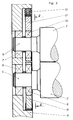
- the cylinder 2 is provided with a pin 4 and cylinder 3 with a pin 5.
- the pin 4 is mounted with the aid of a bearing 6 and the pin 5 with the aid of a bearing 7 in the frame 8 of the device directly and mainly absorbing forces.
- the bearings 6 and 7 are located at that end of the pin 4 or 5 which faces away from the cylinder 2 or 3, respectively.
- a bearing 9 for the pin 4 and a bearing 10 for the pin 5 are provided at those ends of the pins 4 and 5 which face the cylinders 2 and 3. Since the bearings 9 and 10 face the cylinders 2 and 3, one speaks of what are known as inner bearings, in contrast to the so-called outer bearings 6 and 7. It is also possible that the inner bearings have stronger forces than the outer ones or that both types of bearings absorb equally large forces.
- Bearing 9 is surrounded / held by a first part 11 of an auxiliary housing, bearing 10 by a second part 12 of the auxiliary housing.
- the design of the secondary housing 11/12 is particularly apparent from Fig. 2.
- the parts 11 and 12 of the secondary housing are preferably vertically displaceably mounted in corresponding vertical guides located on the frame. These guides are not shown in the figures for better clarity.
- a second pressure medium cylinder 14 is arranged between the second part 12 and the first part 11 and a third pressure medium cylinder 15 is arranged between the first part 11 and frame 8.
- the second pressure medium cylinder like all other pressure medium cylinders, can be a metal bellows cylinder, the parts 11 and 12 are connected to one another by it, since metal bellows cylinders are usually screwed to the machine parts moved by them.
- the pressure medium cylinders 13 and 15 are arranged on one side of the straight line 16, which connects the geometric center 18 of cylinder 3 and the geometric center 17 of cylinder 2 and thus the associated cylinder pins 4 and 5 (on the left in FIG. 2), whereas the second pressure cylinder 14 is arranged on the opposite side (on the right in FIG. 2).
- forces which are exerted, for example, by one of these pressure medium cylinders can be passed through the bearings 9 and 10 such that approximately between the Cylinder pin and the respective bearings existing game can be made ineffective.
- the pressures prevailing in the pressure medium cylinders are preferably generated hydraulically, which is why the proposed device is supplemented by a corresponding pressure generator with a control, setting or regulating unit.
- the associated pressure medium in particular hydraulic oil, can either be supplied to each pressure medium cylinder individually or all pressure medium cylinders together and can also be set, controlled or regulated individually or in groups, depending on the choice. It is therefore possible to supply the cylinders both individually with pressure medium as well as several or even all of the pressure medium cylinders in a fluidically parallel manner with pressure medium.
- the associated pressure medium can also be supplied or controlled in terms of both its quantity and its pressure with the aid of a correspondingly controlled or stored program. This control can depend on the various operating states of the machine, such as. B. different running speeds. But it is also possible to modulate the pressure according to the running speed during operation.
- the pressure medium cylinders can, for example, consist of so-called metal bellows cylinders or other cylinders that allow the use of relatively high pressures. Characterized in that different pressures can be optionally supplied to the pressure medium cylinders and each pressure medium cylinder shown in the figures can also be replaced by several of these pressure medium cylinders, the pressure exerted on the secondary housing 11/12 or the forces exerted on this secondary housing and their points of application can be varied within wide limits.
- each pressure medium cylinder work with a different pressure, so that each pressure medium cylinder is able to produce a different force or forces.
- the forces acting on the so-called auxiliary bearings 9 and 10 can thus also be set within wide limits, preselected or continuously adjusted during operation of the device as desired.
- the so-called main bearings 6 and 7 remain stored in the frame 8 without anything directly changing their storage.
- reaction forces exerted by the pressure medium cylinders also act on these bearings, which, however, can only be an additional side effect.
- a plurality of pressure medium cylinders can also be suitably used, with an increase in complexity Positions.
- the turnbuckle 19 is connected by means of joints 20 and 21 to the parts 11 and 12 of the secondary housing in the usual way.
- at least one pressure medium cylinder 13 per pair of pins of the cylinders involved also remains in the device in the exemplary embodiment according to FIG.
- the exemplary embodiment according to FIG. 4 is, for example, nothing other than a special case of the exemplary embodiment according to FIG. 2, if the device is to be made cheaper on the one hand, but on the other hand is not to be varied as widely as in the example according to FIG. 2.
- An adjusting or regulating device 23 is provided for setting, controlling or regulating, to which pressure medium, such as hydraulic oil, is supplied via a line 24 and a pump 25.
- a sensor 26 is also connected to the control device via line 27.
- the sensor 26 signals the deflection of the cylinders 2 and / or 3 and causes the control device to supply corresponding pressures to the pressure medium cylinders 13 to 15 via lines 28 to 31.
Landscapes
- Engineering & Computer Science (AREA)
- Mechanical Engineering (AREA)
- Paper (AREA)
- Rotary Presses (AREA)
- Rolls And Other Rotary Bodies (AREA)
- Actuator (AREA)
- Fluid-Pressure Circuits (AREA)
- Pivots And Pivotal Connections (AREA)
Claims (7)
- Dispositif pour monter sur paliers un couple de cylindres (2, 3), en particulier pour des cylindres destinés au façonnage de papier, de textile, de matériau en feuilles, de matières plastiques, de métaux et similaires, en rames ou en bande (1), comportant au moins deux paliers (7, 10; 6, 9) par tourillon (4, 5) de chacun des cylindres (2, 3) concerné, la distance des cylindres (2, 3) l'un par rapport à l'autre étant réglable, chacun des paliers (7, 10; 6, 9) d'un tourillon (4, 5) étant disposé dans une pièce (11, 12) d'un carter séparé et ce carter séparé (11, 12) étant équipé d'une installation de mise en pression (13), caractérisé en ce que chacun des paliers (6, 7, 9, 10) se trouvant sur le même tourillon (4, 5) s'appuie sur le bâti (8) commun aux deux cylindres (2, 3), en ce que, pour chaque tourillon de cylindre (4, 5), le palier, extérieur axialement, (6, 7) est monté directement dans le bâti (8), et qu'un autre palier, intérieur axialement, (9, 10), de son coté, est monté dans le bâti (8) en intercalant un carter séparé (11, 12), en ce que l'on peut régler la distance de deux pièces (11,12) du carter séparé, affectées à deux cylindres (2, 3) différents, et qu'au moins un cylindre à fluide de pression (13, 14, 15) est chaque fois prévu pour le réglage des paliers intérieurs axialement (9, 10).
- Dispositif suivant la revendication 1, caractérisé en ce que le carter séparé (11, 12) disposé, axialement,du côté de chacun des cylindres (2, 3), est raccordé au dispositif de mise en pression (13).
- Dispositif suivant la revendication 1, caractérisé en ce que les paliers principaux (6, 7) de chacun des tourillons (4, 5) sont disposés axialement du côté extérieur du cylindre (2, 3).
- Dispositif suivant la revendication 1, caractérisé en ce que des cylindres à fluide de pression (14), ou, au moins, une serrure de mise en tension (19) réglable, sont disposés entre chacune des parties du carter séparé (11, 12), affectées l'une à l'autre.
- Dispositif suivant la revendication 1, caractérisé par au moins un cylindre à fluide de pression (13, 14, 15), ou par une butée réglable (20), se trouvant entre le carter séparé (11, 12) et le bâti (8).
- Dispositif suivant la revendication 1, caractérisé en ce que les cylindres à fluide de pression (13, 14, 15) concernés sont chacun des cylindres à soufflet en métal.
- Dispositif suivant la revendication 1, caractérisé en ce que l'appui, sur le bâti (8), des pièces (11, 12) du carter séparé, associées entre elles, et l'appui, du côté opposé, des pièces (11,12) entre elles correspondent chaque fois à des côtés différents des tourillons de cylindre (4, 5) auxquels elles appartiennent.
Applications Claiming Priority (2)
| Application Number | Priority Date | Filing Date | Title |
|---|---|---|---|
| DE3808142A DE3808142A1 (de) | 1988-03-11 | 1988-03-11 | Lagereinrichtung |
| DE3808143 | 1988-03-11 |
Publications (3)
| Publication Number | Publication Date |
|---|---|
| EP0331875A2 EP0331875A2 (fr) | 1989-09-13 |
| EP0331875A3 EP0331875A3 (en) | 1990-09-12 |
| EP0331875B1 true EP0331875B1 (fr) | 1993-08-18 |
Family
ID=6349490
Family Applications (1)
| Application Number | Title | Priority Date | Filing Date |
|---|---|---|---|
| EP89100462A Expired - Lifetime EP0331875B1 (fr) | 1988-03-11 | 1989-01-12 | Palier |
Country Status (6)
| Country | Link |
|---|---|
| US (1) | US4899656A (fr) |
| EP (1) | EP0331875B1 (fr) |
| JP (1) | JPH01295017A (fr) |
| CA (1) | CA1317336C (fr) |
| DE (2) | DE3808142A1 (fr) |
| ES (1) | ES2011435T3 (fr) |
Families Citing this family (12)
| Publication number | Priority date | Publication date | Assignee | Title |
|---|---|---|---|---|
| US4934838A (en) * | 1989-10-23 | 1990-06-19 | The Hamilton Tool Company | Frame member for supporting multiple bearings with heat barrier slot |
| JP4141142B2 (ja) * | 1999-11-08 | 2008-08-27 | サンエー技研株式会社 | ラミネータ |
| DE10045146A1 (de) * | 2000-09-13 | 2002-05-23 | Ina Schaeffler Kg | Lagerung für Zylinder oder Trommeln in Druckmaschinen |
| DE10152021C2 (de) | 2001-03-20 | 2003-05-08 | Koenig & Bauer Ag | Vorrichtung zum Einstellen des Anpressdrucks einer verstellbar gelagerten Walze |
| EP1461208B1 (fr) * | 2001-12-06 | 2006-03-01 | Koenig & Bauer Aktiengesellschaft | Dispositifs de reglage de rouleaux dans une machine a imprimer |
| DE10244046B4 (de) * | 2002-09-21 | 2006-02-02 | Koenig & Bauer Ag | Vorrichtung zum Einstellen des Anpressdrucks einer verstellbar gelagerten Walze |
| DE10261985A1 (de) | 2002-09-21 | 2004-04-08 | Koenig & Bauer Ag | Vorrichtung zum Einstellen des Anpressdrucks einer verstellbar gelagerten Walze |
| US7521481B2 (en) * | 2003-02-27 | 2009-04-21 | Mclaurin Joanne | Methods of preventing, treating and diagnosing disorders of protein aggregation |
| DE102004037889B4 (de) * | 2004-04-05 | 2006-05-11 | Koenig & Bauer Ag | Vorrichtung zur Lagerung eines Zylinders und Druckeinheit mit wenigstens drei als Druckwerk zusammen wirkenden Zylindern |
| DE102004053187B4 (de) * | 2004-11-04 | 2008-07-03 | Man Roland Druckmaschinen Ag | Anordnung aus aufeinander abrollenden Bauteilen |
| DE102006036050A1 (de) * | 2006-08-02 | 2008-02-07 | Man Roland Druckmaschinen Ag | Vorrichtung zum Andrücken einer Walze |
| ES2632115T5 (es) | 2013-03-07 | 2020-10-30 | Bobst Mex Sa | Disposición ajustable de transformación de un soporte plano, casete, unidad y máquina así equipada |
Family Cites Families (11)
| Publication number | Priority date | Publication date | Assignee | Title |
|---|---|---|---|---|
| US2530425A (en) * | 1949-04-04 | 1950-11-21 | Vlaanderen Machine Company Van | Embossing machine drive |
| DE1253282B (de) * | 1962-08-16 | 1967-11-02 | Goebel Gmbh Maschf | Druckwerk mit beiderseits des Form- und Druckzylinders auf deren Wellen angeordnetenStuetzringen |
| US3326439A (en) * | 1964-09-15 | 1967-06-20 | Harris Intertype Corp | Preloading structure for cooperating cylinders |
| US3338495A (en) * | 1965-08-04 | 1967-08-29 | U S Baird Corp | Adjustably biased separable pressure assembly |
| US3413919A (en) * | 1965-10-23 | 1968-12-03 | Johnson Fast Print Mach Corp | Method and means for supporting the backing cylinder of printing apparatus to facilitate replacing an endless member extending partly around it |
| DE2034490A1 (en) * | 1970-07-11 | 1972-01-27 | SIEMAG Siegener Maschinenbau GmbH, 5912 Hilchenbach Dahlbruch | Roller pivot bearing compensator - hydraulically operated |
| DE2422696C2 (de) * | 1974-05-10 | 1982-12-09 | M.A.N. Maschinenfabrik Augsburg-Nürnberg AG, 8900 Augsburg | Druckwerk für ein- oder beidseitigen Druck mit mindestens vier Zylindern |
| US4048831A (en) * | 1974-08-13 | 1977-09-20 | Hoesch Werke Aktiengesellschaft | Two-roller driving device |
| GB1596841A (en) * | 1977-07-15 | 1981-09-03 | Firth J H | Radar reflector |
| JPS5444255A (en) * | 1977-09-13 | 1979-04-07 | Sanyo Electric Co Ltd | Heat exchanger |
| JPS5876728U (ja) * | 1981-11-19 | 1983-05-24 | 三菱重工業株式会社 | シ−トガイド装置 |
-
1988
- 1988-03-11 DE DE3808142A patent/DE3808142A1/de not_active Withdrawn
-
1989
- 1989-01-11 ES ES198989100388T patent/ES2011435T3/es not_active Expired - Lifetime
- 1989-01-11 DE DE8989100388T patent/DE58904535D1/de not_active Expired - Lifetime
- 1989-01-12 EP EP89100462A patent/EP0331875B1/fr not_active Expired - Lifetime
- 1989-03-10 US US07/321,315 patent/US4899656A/en not_active Expired - Fee Related
- 1989-03-10 CA CA000593358A patent/CA1317336C/fr not_active Expired - Fee Related
- 1989-03-13 JP JP1058064A patent/JPH01295017A/ja active Pending
Also Published As
| Publication number | Publication date |
|---|---|
| JPH01295017A (ja) | 1989-11-28 |
| DE58904535D1 (de) | 1993-07-08 |
| US4899656A (en) | 1990-02-13 |
| EP0331875A3 (en) | 1990-09-12 |
| CA1317336C (fr) | 1993-05-04 |
| DE3808142A1 (de) | 1989-09-21 |
| EP0331875A2 (fr) | 1989-09-13 |
| ES2011435A4 (es) | 1990-01-16 |
| ES2011435T3 (es) | 1993-11-16 |
Similar Documents
| Publication | Publication Date | Title |
|---|---|---|
| EP0331870B1 (fr) | Palier | |
| DE69431492T2 (de) | Kalender zum Kalandrieren einer Papierbahn | |
| DE2843743C2 (fr) | ||
| DE69604330T2 (de) | Verbesserungen in oder in Verband mit einer Einrichtung zum Kreuzen oder axialen Verschieben von Walzen | |
| DE3004915C2 (de) | Kalander | |
| DE3212070C2 (de) | Walzgerüst mit einer Vorrichtung zur Einhaltung der Ebenheit des gewalzten Guts | |
| DE3004913A1 (de) | Kalander | |
| DE4327646C2 (de) | Breiten-Einstellverfahren für eine Papierbahn sowie damit ausgerüstete lithographische Rotationspresse | |
| DE3201635C2 (de) | Kalanderanordnung | |
| DE3025799C2 (de) | Preßwalze, deren Durchbiegung einstellbar ist | |
| EP0331875A2 (fr) | Palier | |
| EP2814627B1 (fr) | Presse à cintrer doté d'élément barre réglable | |
| DE69205554T2 (de) | Rotationsstanzvorrichtung. | |
| DE3634198C2 (fr) | ||
| DE4114313A1 (de) | Laminator | |
| EP0534160B1 (fr) | Machine à imprimer rotative | |
| DE69924466T2 (de) | Abstreifvorrichtung für flüssigkeiten | |
| DE29780451U1 (de) | Hochgenaues Walzwerk mit zweidimensionaler Biegungssteuerung | |
| DE1602184B2 (de) | Vielwalzen-Gerüstanordnung | |
| DE19821603A1 (de) | Längsfalzeinrichtung am Falzapparat von Rotationsdruckmaschinen | |
| DE942554C (de) | Kniehebelpresse | |
| DE3300251C2 (fr) | ||
| DE2456782A1 (de) | Verfahren und vorrichtung zum richten von profilstahl | |
| DE3400608C2 (de) | Walzgerüst mit einer zwischen Arbeitswalze und Stützwalze eingefügten versetzten Zwischenwalze | |
| EP0179395B1 (fr) | Dispositif de couchage pour installation de carton ondulé |
Legal Events
| Date | Code | Title | Description |
|---|---|---|---|
| PUAI | Public reference made under article 153(3) epc to a published international application that has entered the european phase |
Free format text: ORIGINAL CODE: 0009012 |
|
| AK | Designated contracting states |
Kind code of ref document: A2 Designated state(s): BE CH DE ES FR GB IT LI NL SE |
|
| ITCL | It: translation for ep claims filed |
Representative=s name: BARZANO' E ZANARDO MILANO S.P.A. |
|
| GBC | Gb: translation of claims filed (gb section 78(7)/1977) | ||
| EL | Fr: translation of claims filed | ||
| TCNL | Nl: translation of patent claims filed | ||
| PUAL | Search report despatched |
Free format text: ORIGINAL CODE: 0009013 |
|
| AK | Designated contracting states |
Kind code of ref document: A3 Designated state(s): BE CH DE ES FR GB IT LI NL SE |
|
| 17P | Request for examination filed |
Effective date: 19900912 |
|
| 17Q | First examination report despatched |
Effective date: 19920910 |
|
| GRAA | (expected) grant |
Free format text: ORIGINAL CODE: 0009210 |
|
| ITF | It: translation for a ep patent filed | ||
| AK | Designated contracting states |
Kind code of ref document: B1 Designated state(s): BE CH DE ES FR GB IT LI NL SE |
|
| REF | Corresponds to: |
Ref document number: 58905297 Country of ref document: DE Date of ref document: 19930923 |
|
| ET | Fr: translation filed | ||
| GBT | Gb: translation of ep patent filed (gb section 77(6)(a)/1977) |
Effective date: 19931001 |
|
| REG | Reference to a national code |
Ref country code: ES Ref legal event code: FG2A Ref document number: 2011436 Country of ref document: ES Kind code of ref document: T3 |
|
| PLBE | No opposition filed within time limit |
Free format text: ORIGINAL CODE: 0009261 |
|
| STAA | Information on the status of an ep patent application or granted ep patent |
Free format text: STATUS: NO OPPOSITION FILED WITHIN TIME LIMIT |
|
| 26N | No opposition filed | ||
| EAL | Se: european patent in force in sweden |
Ref document number: 89100462.4 |
|
| PGFP | Annual fee paid to national office [announced via postgrant information from national office to epo] |
Ref country code: DE Payment date: 19971208 Year of fee payment: 10 |
|
| PGFP | Annual fee paid to national office [announced via postgrant information from national office to epo] |
Ref country code: FR Payment date: 19971229 Year of fee payment: 10 |
|
| PGFP | Annual fee paid to national office [announced via postgrant information from national office to epo] |
Ref country code: GB Payment date: 19980105 Year of fee payment: 10 |
|
| PGFP | Annual fee paid to national office [announced via postgrant information from national office to epo] |
Ref country code: BE Payment date: 19980114 Year of fee payment: 10 |
|
| PGFP | Annual fee paid to national office [announced via postgrant information from national office to epo] |
Ref country code: ES Payment date: 19980115 Year of fee payment: 10 |
|
| PGFP | Annual fee paid to national office [announced via postgrant information from national office to epo] |
Ref country code: SE Payment date: 19980119 Year of fee payment: 10 |
|
| PGFP | Annual fee paid to national office [announced via postgrant information from national office to epo] |
Ref country code: NL Payment date: 19980130 Year of fee payment: 10 |
|
| PGFP | Annual fee paid to national office [announced via postgrant information from national office to epo] |
Ref country code: CH Payment date: 19980430 Year of fee payment: 10 |
|
| PG25 | Lapsed in a contracting state [announced via postgrant information from national office to epo] |
Ref country code: DE Free format text: LAPSE BECAUSE OF THE APPLICANT RENOUNCES Effective date: 19981112 |
|
| PG25 | Lapsed in a contracting state [announced via postgrant information from national office to epo] |
Ref country code: GB Free format text: LAPSE BECAUSE OF NON-PAYMENT OF DUE FEES Effective date: 19990112 |
|
| PG25 | Lapsed in a contracting state [announced via postgrant information from national office to epo] |
Ref country code: SE Free format text: LAPSE BECAUSE OF NON-PAYMENT OF DUE FEES Effective date: 19990113 Ref country code: ES Free format text: LAPSE BECAUSE OF NON-PAYMENT OF DUE FEES Effective date: 19990113 |
|
| PG25 | Lapsed in a contracting state [announced via postgrant information from national office to epo] |
Ref country code: LI Free format text: LAPSE BECAUSE OF NON-PAYMENT OF DUE FEES Effective date: 19990131 Ref country code: CH Free format text: LAPSE BECAUSE OF NON-PAYMENT OF DUE FEES Effective date: 19990131 Ref country code: BE Free format text: LAPSE BECAUSE OF NON-PAYMENT OF DUE FEES Effective date: 19990131 |
|
| BERE | Be: lapsed |
Owner name: MASCHINENFABRIK GOEBEL G.M.B.H. Effective date: 19990131 |
|
| PG25 | Lapsed in a contracting state [announced via postgrant information from national office to epo] |
Ref country code: NL Free format text: LAPSE BECAUSE OF NON-PAYMENT OF DUE FEES Effective date: 19990801 |
|
| GBPC | Gb: european patent ceased through non-payment of renewal fee |
Effective date: 19990112 |
|
| REG | Reference to a national code |
Ref country code: CH Ref legal event code: PL |
|
| PG25 | Lapsed in a contracting state [announced via postgrant information from national office to epo] |
Ref country code: FR Free format text: LAPSE BECAUSE OF NON-PAYMENT OF DUE FEES Effective date: 19990930 |
|
| REG | Reference to a national code |
Ref country code: FR Ref legal event code: ST |
|
| REG | Reference to a national code |
Ref country code: ES Ref legal event code: FD2A Effective date: 20010503 |
|
| PG25 | Lapsed in a contracting state [announced via postgrant information from national office to epo] |
Ref country code: IT Free format text: LAPSE BECAUSE OF NON-PAYMENT OF DUE FEES;WARNING: LAPSES OF ITALIAN PATENTS WITH EFFECTIVE DATE BEFORE 2007 MAY HAVE OCCURRED AT ANY TIME BEFORE 2007. THE CORRECT EFFECTIVE DATE MAY BE DIFFERENT FROM THE ONE RECORDED. Effective date: 20050112 |