EP0333157A1 - Procédé de contrôle du transport d'une feuille photoréceptive - Google Patents
Procédé de contrôle du transport d'une feuille photoréceptive Download PDFInfo
- Publication number
- EP0333157A1 EP0333157A1 EP89104583A EP89104583A EP0333157A1 EP 0333157 A1 EP0333157 A1 EP 0333157A1 EP 89104583 A EP89104583 A EP 89104583A EP 89104583 A EP89104583 A EP 89104583A EP 0333157 A1 EP0333157 A1 EP 0333157A1
- Authority
- EP
- European Patent Office
- Prior art keywords
- photoreceptive sheet
- sheet
- image forming
- photoreceptive
- exposure
- Prior art date
- Legal status (The legal status is an assumption and is not a legal conclusion. Google has not performed a legal analysis and makes no representation as to the accuracy of the status listed.)
- Granted
Links
- 238000000034 method Methods 0.000 title claims abstract description 34
- 238000012545 processing Methods 0.000 description 14
- 239000003094 microcapsule Substances 0.000 description 12
- 238000012546 transfer Methods 0.000 description 11
- 238000006073 displacement reaction Methods 0.000 description 9
- 230000015572 biosynthetic process Effects 0.000 description 8
- 238000011161 development Methods 0.000 description 8
- 230000018109 developmental process Effects 0.000 description 8
- 238000006243 chemical reaction Methods 0.000 description 6
- 239000000463 material Substances 0.000 description 6
- 230000003287 optical effect Effects 0.000 description 5
- 238000010438 heat treatment Methods 0.000 description 4
- 238000012986 modification Methods 0.000 description 3
- 230000004048 modification Effects 0.000 description 3
- 239000000758 substrate Substances 0.000 description 3
- 230000006866 deterioration Effects 0.000 description 2
- 238000010586 diagram Methods 0.000 description 2
- 230000000694 effects Effects 0.000 description 2
- 230000002093 peripheral effect Effects 0.000 description 2
- 229920001169 thermoplastic Polymers 0.000 description 2
- 239000004416 thermosoftening plastic Substances 0.000 description 2
- 230000005540 biological transmission Effects 0.000 description 1
- 239000011248 coating agent Substances 0.000 description 1
- 238000000576 coating method Methods 0.000 description 1
- 239000011521 glass Substances 0.000 description 1
- 239000000543 intermediate Substances 0.000 description 1
- 229920000728 polyester Polymers 0.000 description 1
- 230000002265 prevention Effects 0.000 description 1
- 230000004044 response Effects 0.000 description 1
Images







Classifications
-
- G—PHYSICS
- G03—PHOTOGRAPHY; CINEMATOGRAPHY; ANALOGOUS TECHNIQUES USING WAVES OTHER THAN OPTICAL WAVES; ELECTROGRAPHY; HOLOGRAPHY
- G03B—APPARATUS OR ARRANGEMENTS FOR TAKING PHOTOGRAPHS OR FOR PROJECTING OR VIEWING THEM; APPARATUS OR ARRANGEMENTS EMPLOYING ANALOGOUS TECHNIQUES USING WAVES OTHER THAN OPTICAL WAVES; ACCESSORIES THEREFOR
- G03B27/00—Photographic printing apparatus
- G03B27/32—Projection printing apparatus, e.g. enlarger, copying camera
-
- G—PHYSICS
- G03—PHOTOGRAPHY; CINEMATOGRAPHY; ANALOGOUS TECHNIQUES USING WAVES OTHER THAN OPTICAL WAVES; ELECTROGRAPHY; HOLOGRAPHY
- G03B—APPARATUS OR ARRANGEMENTS FOR TAKING PHOTOGRAPHS OR FOR PROJECTING OR VIEWING THEM; APPARATUS OR ARRANGEMENTS EMPLOYING ANALOGOUS TECHNIQUES USING WAVES OTHER THAN OPTICAL WAVES; ACCESSORIES THEREFOR
- G03B27/00—Photographic printing apparatus
- G03B27/32—Projection printing apparatus, e.g. enlarger, copying camera
- G03B27/52—Details
- G03B27/58—Baseboards, masking frames, or other holders for the sensitive material
- G03B27/587—Handling photosensitive webs
- G03B27/588—Supply rolls; Cutting arrangements
-
- G—PHYSICS
- G03—PHOTOGRAPHY; CINEMATOGRAPHY; ANALOGOUS TECHNIQUES USING WAVES OTHER THAN OPTICAL WAVES; ELECTROGRAPHY; HOLOGRAPHY
- G03F—PHOTOMECHANICAL PRODUCTION OF TEXTURED OR PATTERNED SURFACES, e.g. FOR PRINTING, FOR PROCESSING OF SEMICONDUCTOR DEVICES; MATERIALS THEREFOR; ORIGINALS THEREFOR; APPARATUS SPECIALLY ADAPTED THEREFOR
- G03F7/00—Photomechanical, e.g. photolithographic, production of textured or patterned surfaces, e.g. printing surfaces; Materials therefor, e.g. comprising photoresists; Apparatus specially adapted therefor
- G03F7/002—Photomechanical, e.g. photolithographic, production of textured or patterned surfaces, e.g. printing surfaces; Materials therefor, e.g. comprising photoresists; Apparatus specially adapted therefor using materials containing microcapsules; Preparing or processing such materials, e.g. by pressure; Devices or apparatus specially designed therefor
- G03F7/0022—Devices or apparatus
-
- G—PHYSICS
- G03—PHOTOGRAPHY; CINEMATOGRAPHY; ANALOGOUS TECHNIQUES USING WAVES OTHER THAN OPTICAL WAVES; ELECTROGRAPHY; HOLOGRAPHY
- G03B—APPARATUS OR ARRANGEMENTS FOR TAKING PHOTOGRAPHS OR FOR PROJECTING OR VIEWING THEM; APPARATUS OR ARRANGEMENTS EMPLOYING ANALOGOUS TECHNIQUES USING WAVES OTHER THAN OPTICAL WAVES; ACCESSORIES THEREFOR
- G03B2227/00—Photographic printing apparatus
- G03B2227/32—Projection printing apparatus, e.g. enlarging apparatus, copying camera
- G03B2227/325—Microcapsule copiers
Definitions
- the present invention generally relates to an image forming apparatus employing a photoreceptive sheet and an image receiving sheet and more particularly, to a method of controlling transport of the photoreceptive sheet to an image forming exposure position and an image forming position.
- An image forming method employing an image forming sheet is disclosed in, for example, in Japanese Patent Laid-Open Publication No. 88739/1983 which employs not only a photoreceptive sheet coated with photosensitive resinous microcapsules containing colorless dye and photo-setting material but an image receiving sheet coated with developing material for effecting color development of the colorless dye.
- a selectively set image has been formed on the photoreceptive sheet by image forming exposure, the image receiving sheet is placed on the photoreceptive sheet so as to be pressed against the photoreceptive sheet such that unset photosensitive microcapsules are ruptured.
- the colorless dye contained in the photosensitive microcapsules is subjected to color development on the image receiving sheet so as to obtain an image.
- the photoreceptive sheet is transported through an exposure position for performing image forming exposure and an image forming position for pressing the photoreceptive sheet, while the image receiving sheet is transported through the image forming position.
- the image receiving sheet is placed on the photoreceptive sheet having the selectively set image formed thereon by image forming exposure at the exposure position so as to be pressed against the photoreceptive sheet.
- the photosensitive microcapsules of an exposed portion of the photoreceptive sheet should be set sufficiently and complete reaction between the colorless dye and the developing material should take place on the image receiving sheet. Rate of photo-setting reaction of the photosensitive microcapsules is different from rate of color development reaction of the colorless dye on the image receiving sheet. Therefore, in order to obtain a proper image, not only feed rate of the photoreceptive sheet at the exposure position is required to coincide with an optimum exposure speed for effecting photo-setting reaction of the photosensitive microcapsules but feed rate of the photoreceptive sheet at the image forming position is required to coincide with an optimum image forming speed for effecting color development reaction of the colorless dye.
- a pressing device for pressing the photoreceptive sheet and the image receiving sheet against each other is constituted by a pair of rollers such that the photoreceptive sheet is transported through rotation of the rollers. Therefore, transport speed of the photoreceptive sheet coincides with peripheral speed of the rollers and thus, feed rate of the photoreceptive sheet at the exposure position is identical with feed rate of the photoreceptive sheet at the image forming position. Consequently, it becomes impossible to set either one or both of feed rates of the photoreceptive sheet at the exposure position and the image forming position to the optimum speed or the optimum speeds, thereby resulting in deterioration of the formed image.
- an essential object of the present invention is to provide a method of controlling transport of a photoreceptive sheet, in which feed rate of the photoreceptive sheet at an exposure position and feed rate of the photoreceptive sheet at an image forming position can be separately set and controlled such that an excellent image is obtained.
- a method of controlling transport of a photoreceptive sheet comprises the steps of: feeding the photoreceptive sheet from a roll of the photoreceptive sheet to an exposure position so as to subject the photoreceptive sheet to image forming exposure and transporting the exposed photoreceptive sheet to a buffer region; transporting to an image forming position, the photoreceptive sheet disposed at the buffer region; and feeding to the image forming position, the photoreceptive sheet disposed between the exposure position and the image forming position.
- feed rate of the photoreceptive sheet can be set to an optimum exposure speed and thus, image forming exposure of the photoreceptive sheet is performed properly.
- feed rate of the photoreceptive sheet can be set to an optimum image forming speed and therefore, an excellent image is formed.
- a method of controlling transport of a photoreceptive sheet comprises the steps of: feeding the photoreceptive sheet from a roll of the photoreceptive sheet to an exposure position so as to subject the photoreceptive sheet to image forming exposure and transporting the exposed photoreceptive sheet to a buffer region; transporting to the buffer region, the photoreceptive sheet disposed at the exposure position; and transporting to an image forming position, the photoreceptive sheet disposed at the buffer region.
- feed rate of the photoreceptive sheet can be set to an optimum exposure speed and thus, image forming exposure of the photoreceptive sheet is performed properly.
- feed rate of the photoreceptive sheet can be set to an optimum image forming speed, an excellent image is obtained.
- a supply shaft for the roll of the photoreceptive sheet is locked.
- the image forming apparatus includes an apparatus housing 21.
- An original platform 29 made of hard glass having light transmission properties is provided on an upper face of the apparatus housing 21.
- An optical system 22 is constituted by a light source 23, mirrors 24 to 27 and a lens 28 and is disposed below the original platform 29.
- the light source 22 and the mirrors 24 to 26 are movable below the original platform 29 in the directions of the arrows G and H so as to scan an original document placed on the original platform 29.
- upper and lower pressure rollers 32 and 33 are provided in pressing contact with each other so as to constitute a pressing portion 31.
- a point of contact between the upper and lower pressure rollers 32 and 33 is an image forming position P2 of the present invention.
- a sheet storage portion 39 for accommodating the photoreceptive sheet 34 is provided at the left side of the upper pressure roller 32.
- the sheet storage portion 39 includes a supply shaft 35 and a take-up shaft 36.
- the photoreceptive sheet 34 is wound around the supply shaft 35 so as to form a roll of the photoreceptive sheet 34.
- the photoreceptive sheet 34 is obtained by coating on a substrate made of polyester, etc., photosensitive microcapsules containing colorless dye and photo-setting material.
- photosensitive microcapsules are not coated on the substrate and the substrate has rigidity larger than that of the remaining portion of the photoreceptive sheet 34 such that the distal end portion of the photoreceptive sheet 34 acts as a leader portion at the time of initial loading of the photoreceptive sheet 34 to the image forming apparatus.
- the photoreceptive sheet 34 is wound around an outer periphery of the take-up shaft 36 through a plurality of rollers 37, a suspended roller 78 and the image forming position P2 between the upper and lower pressure rollers 32 and 33.
- a lock mechanism for locking the supply shaft 35 is provided locks the supply shaft 35 at a necessary time so as to stop supply of the photoreceptive sheet 34.
- Figs. 6 and 7 show the lock mechanism for locking the supply shaft 35. It is to be noted that Fig. 7 is viewed in a direction identical with that of Fig. 3.
- a gear 35a having a saw-toothed peripheral surface is fixedly mounted on one end of the supply shaft 35 having the photoreceptive sheet 34 wound therearound.
- an actuator piece 35c having an engageable portion 35d formed at its one distal end portion is pivotally provided so as to be pivoted about a support shaft 35b.
- a solenoid 35e and a spring 35f are attached to the other end of the actuator piece 35c remote from the engageable portion 35d so as to apply opposite urging forces to the actuator piece 35c, respectively.
- the solenoid 35e pulls the actuator piece 45c in the direction of the arrow M against the tensile force of the spring 35f so as to pivot the actuator piece 35c in the direction of the arrow M such that the engageable portion 35d is disengaged from the gear 35a.
- the spring 35f pulls the actuator piece 35c in the direction of the arrow N so as to engage the engageable portion 35d with the gear 35a.
- the gear 35a namely, the supply shaft 35 becomes rotatable in the both directions of the arrows K and L, so that supply of the photoreceptive sheet 34 can be performed.
- the supply shaft 35 can be rotated only in the direction of the arrow K such that feed of the photoreceptive sheet 34 from the supply shaft 35 is locked.
- the solenoid 35e is also in OFF state, so that the supply shaft 35 is locked and thus, a slack is not formed on the photoreceptive sheet 34.
- a cassette 42 for accommodating image receiving sheets 46a and a cassette 43 for accommodating image receiving sheets 46b are loaded into a right side portion of the apparatus housing 21, while paper feeding rollers 44 and 45 are, respectively, provided above the cassettes 42 and 43.
- the cassettes 42 and 43 and the paper feeding rollers 44 and 45 constitute a paper feeding portion 41.
- Developing material for effecting color development of the colorless dye contained in the photosensitive microcapsules, thermoplastic for imparting gloss to a formed image, etc. are coated on the surface of each of the image receiving sheets 46a and 46b accommodated in the cassettes 42 and 43, respectively.
- the image receiving sheets 46a of the cassette 42 or the image receiving sheets 46b of the cassette 43 are fed one sheet by one sheet from an uppermost one of the image receiving sheets 46a or 46b. Then, the image receiving sheet 46a or 46b is carried to the image forming position P2 of the pressing portion 31 through timing rollers 51. At the image forming position P2, the image receiving sheet 46a or 46b is placed on the photoreceptive sheet 34 having a selectively set image formed thereon so as to be pressed against the photoreceptive sheet 34. The image receiving sheet 46a or 46b having passed through the image forming position P2 is drawn to a heat roller 55 by a transport belt 53 so as to be heated by the heat roller 55.
- thermoplastic is set in a softened or molten state so as to impart gloss to the image as disclosed in, for example, Japanese Patent Laid-Open Publication No. 259490/1985.
- the image receiving sheet 46a or 46b having passed through the heat roller 55 is discharged onto a copy receiving tray 57 by a pair of discharge rollers 56.
- the image of the original document scanned by the optical system 22 is conveyed to an exposure position P1 via the mirrors 24 to 27 and the lens 28.
- the photoreceptive sheet 34 receives, at the exposure position P1, reflected light from the original document such that a selectively set image is formed on the surface of the photoreceptive sheet 34.
- the suspended roller 78 is movably provided between the exposure position P1 and the image forming position P2 so as to be moved in the directions of the arrows I and J.
- the photoreceptive sheet 34 having passed through the exposure position P1 is transported to the image forming position P2 of the pressing portion 31 through the suspended roller 78.
- a buffer region R of the present invention is provided at an upwardly and obliquely right location of the exposure position P1.
- the suspended roller 78 having the photoreceptive sheet 34 folded therearound is displaced in the direction of the arrow I, the exposed photoreceptive sheet 34 is carried to the buffer region R.
- Fig. 4 shows vicinity of the suspended roller 78
- Fig. 5 shows a drive mechanism for driving the suspended roller 78
- the suspended roller 78 is supported by a guide 11.
- a bearing portion 11a is formed at one end portion of the guide 11.
- a support rod 12 secured to the apparatus housing 21 is fitted into the bearing portion 11a such that the bearing portion 11a is moved along the support rod 12 in the directions of the arrows I and J of Fig. 3.
- a roller 13 is provided at the other end of the guide 11 so as to rotate between a pair of rails 14a and 14b.
- One end of a wire 17 is attached to an intermediate portion of one wall face of the guide 11. The wire 17 is trained over a roller 15 secured to a shaft 16.
- the other end of the wire 17 is attached to the other wall face of the guide 11 through a pulley 90 disposed at one side of the upper pressure roller 32. Meanwhile, it can also be so arranged that by eliminating the pulley 90, the other end of the wire 17 is fixed to the roller 15 such that the wire 17 is wound around the roller 15.
- the shaft 16 is supported by a frame 10 of the apparatus housing 21 such that rotation of a motor 1 is transmitted to the shaft 16 through gears 2 to 7, an electromagnetic clutch 8 and a torque limiter 9.
- the electromagnetic clutch 8 When voltage has been applied to the electromagnetic clutch 8, the electromagnetic clutch 8 is brought into engagement with the gear 6 so as to transmit rotation of the motor 1 to the gear 7.
- the shaft 16 is rotated in the direction of the arrow A in Fig. 4 by the motor 1.
- the torque limiter 9 incorporates a one-way clutch so as to regulate to not more than a predetermined value, rotational speed of the shaft 16 during rotation of the shaft 16 in the direction of the arrow B in Fig. 4.
- a home position sensor 81 and a stroke limit sensor 82 are, respectively, provided at a home position of the suspended roller 78 and a stroke limit of the suspended roller 78, respectively so as to detect position of the suspended roller 78.
- Fig. 8 is a block diagram showing a control portion of the image forming apparatus of Fig. 3.
- the image forming apparatus as a whole is controlled by a main central processing unit (MCPU) 61 whose processing program is stored in a read-only memory (ROM) 62.
- the MCPU 61 outputs control signals to the electromagnetic clutch 8 of the drive mechanism for the suspended roller 78, the solenoid 35e for the roll of the photoreceptive sheet 34, the clutch for the upper pressure roller 32 and other solenoids.
- the MCPU 61 gives control commands to a subordinate central processing unit (SCPU) 63 for controlling the motor 1 of the drive mechanism for the suspended roller 78.
- SCPU 63 controls the motor 1 on the basis of a processing program stored in a ROM 64.
- a processing sequence of the suspended roller 78 and the upper and lower pressure rollers 32 and 33 at the time when a copying operation of the image forming apparatus of Fig. 3 is performed in the method according to the first embodiment of the present invention is described with reference to flow charts of Figs. 1a and 1b. If input of data such as size of an image to be formed and operation of a print start switch have been performed on an operating panel (not shown) on the apparatus housing 21, the program flow starts.
- the motor 1 of the drive mechanism for the suspended roller 78, the clutch 8 and the solenoid 35e for the supply shaft 35 are turned on so as to cancel locking of the supply shaft 35.
- the suspended roller 78 is displaced in the direction of the arrow I so as to draw the photoreceptive sheet 34 from the supply shaft 35.
- the photoreceptive sheet 34 drawn from the supply shaft 35 is subjected to exposure at the exposure position P1 by reflected light introduced from the original document by the optical system 22 such that a selectively set image is formed on the photoreceptive sheet 34.
- the exposed photoreceptive sheet 34 is carried to the buffer region R through displacement of the suspended roller 78 in the direction of the arrow I.
- step n5 the solenoid 35e for the supply shaft 35 is turned off so as to prevent the supply shaft 35 from rotating in the direction of the arrow L and thus, the photoreceptive sheet 34 cannot be drawn from the supply shaft 35.
- step n6 the clutch for the upper pressure roller 32 is turned on so as to rotate the upper and lower pressure rollers 32 and 33 by a drive unit (not shown) and the suspended roller 78 is pulled by the photoreceptive sheet 34 so as to be carried in the direction of the arrow J.
- the photoreceptive sheet 34 disposed at the buffer region R is transported to the image forming position P2 between the upper and lower pressure rollers 32 and 33 and thus, the image receiving sheet 46a or 46b is placed on the photoreceptive sheet 34 so as to be pressed against the photoreceptive sheet 34.
- unset photosensitive microcapsules of the photoreceptive sheet 34 are ruptured and color development of colorless dye flowing out of the ruptured photosensitive microcapsules is performed by developing material of the image receiving sheet 46a or 46b such that an image is formed on the image receiving sheet 46a or 46b.
- feed of the photoreceptive sheet 34 from the roll of the photoreceptive sheet 34 is prevented positively by locking the supply shaft 35.
- load of the supply shaft 35 is adjusted, thereby eliminating the need for provision of the lock mechanism for locking the supply shaft 35. Displacement of the suspended roller 78 in the direction of the arrow J is continued until the home position sensor 81 is turned on at step n7.
- step n8 the solenoid 35e for the supply shaft 35 is turned on so as to cancel locking of the supply shaft 35.
- the photoreceptive sheet 34 is drawn from the supply shaft 35 upon rotation of the upper and lower pressure rollers 32 and 33 and the image receiving sheet 46a or 46b is placed on the photoreceptive sheet 34 so as to be pressed against the photoreceptive sheet 34.
- Draw of the photoreceptive sheet 34 from the supply shaft 35 is performed until at least the rear end of the selectively set image on the photoreceptive sheet 34 passes through the image forming position P2 at step n10.
- the clutch for driving the upper pressure roller 42 is turned off so as to stop rotation of the upper and lower pressure rollers 32 and 33 and the solenoid 35e for the supply shaft 35 is turned off so as to lock the supply shaft 35 at step n11.
- steps n2 and n3 correspond to the first step of Claim 1
- steps n4, n6 and n7 correspond to the second step of Claim 1
- steps n9 and n10 correspond to the third step of Claim 1.
- a modified processing sequence of the suspended roller 78 and the upper and lower pressure rollers 32 and 33 at the time of a copying operation in the image forming apparatus of Fig. 3 is described with reference to flow charts of Figs. 2a and 2b.
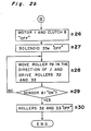
- This processing sequence is based on the method of Claim 2 of the present invention. Steps n21 to n23 are executed in the same manner as step n1 to n3 of Fig. 1a. However, in this modified processing sequence, even after completion of exposure, the suspended roller 78 is continuously displaced in the direction of the arrow I at step n24.
- step n25 If it is found at step n25 that the photoreceptive sheet 34 has been conveyed to the buffer region R through the size of the image to be formed, namely the photoreceptive sheet 34 disposed at the exposure position at the time of completion of exposure (rear end of the selectively set image) has been conveyed to the buffer region R by the suspended roller 78, the motor 1 and the clutch 8 are turned off at step n26 so as to stop the suspended roller 78. Subsequently, at step n27, the solenoid 35e for the supply shaft 35 is locked.
- step n28 the clutch for the upper pressure roller 32 is actuated so as to rotate the upper and lower pressure rollers 32 and 33 and the suspended roller 78 is displaced in the direction of the arrow J by a pulling force of the photoreceptive sheet 34 such that pressure transfer is performed.
- step n29 that the home position sensor 81 has been turned on, namely pressure transfer up to the rear end of the selectively set image on the photosensitive sheet 34 has been completed, the clutch for the upper pressure roller 32 is turned off at step n30 so as to stop rotation of the upper and lower pressure rollers 32 and 33.
- steps n22 and n23 correspond to the first step of Claim 2
- steps n24 and n25 correspond to the second step of Claim 2
- steps n28 and n29 correspond to the third step of Claim 2.
- "locking of the supply shaft 35 when the photoreceptive sheet 34 disposed at the buffer region R is transported to the image forming position P2" corresponds to step n5 of Fig. 1a or step n27 of Fig. 2b.
- feed rate of the photoreceptive sheet at the time of exposure and feed rate of the photoreceptive sheet at the time of image formation can be separately set to optimum values, respectively, an excellent image can be obtained through prevention of deterioration of image quality.
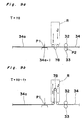
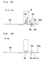
- Figs. 9a to 9d show transport states of the photoreceptive sheet 34 in a method of controlling transport of the photoreceptive sheet 34, according to a second embodiment of the present invention.
- a portion 34a of the photoreceptive sheet 34 which is shown by a bold line, is an image area in which the selectively set image is formed.
- the image area 34a has a front end 34a-1 and a rear end 34a-2.
- the image area 34a is subjected to exposure at the exposure position P1 by the optical system 22.
- Reference numeral 46 denotes the image receiving sheet 46a or 46b of Fig. 3.
- the image receiving sheet 46 is placed on the image area 34a of the photoreceptive sheet 34 so as to be pressed against the photoreceptive sheet 34 such that pressure transfer is performed.
- a high pressure is applied to the photoreceptive sheet 34 at all times by the upper and lower pressure rollers 32 and 33. Pressure transfer is performed upon rotation of the upper and lower pressure rollers 32 and 33 in the directions of the arrows shown in Fig. 9c.
- the suspended roller 78 is disposed between the exposure position P1 and the image forming position P2.
- the buffer region R is disposed at one side of the photoreceptive sheet 34 remote from the suspended roller 78.
- the photoreceptive sheet 34 Upon displacement of the suspended roller 78 in the direction of the arrow I, the photoreceptive sheet 34 is folded around the suspended roller 78 so as to be carried to the buffer region R. On the other hand, upon displacement of the suspended roller 78 in the direction of the arrow J, the photoreceptive sheet 34 disposed at the buffer region R is fed to the image forming position P2.
- the image area 34a of the photoreceptive sheet 34 is subjected to exposure at the exposure position P1 such that the selectively set image is formed on the photoreceptive sheet 34.
- the suspended roller 78 is displaced in the direction of the arrow I, the photoreceptive sheet 34 is drawn from the supply shaft 35 so as to be carried to the buffer region R such that the photoreceptive sheet 34 is subjected to exposure at the exposure position P1 while being drawn from the supply shaft 35.
- the upper and lower pressure rollers 32 and 33 are not driven and only the exposure process is performed. Therefore, if feed rate of the suspended roller 78 in the direction of the arrow I is set to an optimum exposure speed (first speed V1), exposure can be performed excellently.
- a predetermined time period t1 displacement of the suspended roller 78 at feed rates corresponding to the optimum exposure speed and an optimum image forming speed (second speed V2) is started and the upper and lower pressure rollers 32 and 33 are rotated such that pressure transfer is performed simultaneously with exposure.
- the optimum image forming speed is higher than the optimum exposure speed.
- the suspended roller 78 is displaced in the direction of the arrow J at the second speed V2.
- Fig. 9c shows a state in which the suspended roller 78 is being displaced in the direction of the arrow J. In Fig.
- the photoreceptive sheet 34 disposed at the buffer region R is transported to the image forming position P2.
- the image receiving sheet 46 is also conveyed to the image forming position P2 where the image receiving sheet 46 is placed on the image area 34a of the photoreceptive sheet 34 so as to be pressed against the image area 34a such that an image subjected to color development is formed on the image receiving sheet 46 through rupture of unset photosensitive microcapsules.
- Fig. 9d shows a state in which image formation has been completed.
- the rear end 34a-2 of the image area 34a is carried to a location slightly downstream of the upper and lower pressure rollers 32 and 33.
- a time point for starting displacement of the suspended roller 78 performed at the second speed V2 is set such that the state of Fig. 9d is obtained when the suspended roller 78 has been returned to the home position. This is because such phenomenon is prevented that image formation is completed in a state where the rear end of the image receiving sheet 46 is gripped between the upper and lower pressure rollers 32 and 33.
- character V1 denotes the optimum exposure speed (first speed)
- character V2 denotes the optimum image forming speed (second speed).
- character V3 denotes speed of the suspended roller 78 in the direction of the arrow I
- character V4 denotes speed of the suspended roller 78 in the direction of the arrow J
- character L denotes a length of the image area 34a
- character l denotes a distance obtained by adding a length ⁇ of about 5-20 mm to a distance between the exposure position P1 and the image forming position P2
- character t0 denotes a time point of start of exposure
- character t1 denotes a time period between the time point t0 and a time point of start of pressure transfer
- character t2 denotes a time period between the time point t0 and a time point of completion of pressure transfer.
- the length ⁇ is provided for transporting the rear end 34a-2 of the image area 34a, i.e. the rear end of the image receiving sheet 46 to a location slightly downstream of the upper and lower pressure rillers 32 and 33 at the time of completion of image formation.
- the first and second speeds V1 and V2 are determined according to kinds of the photoreceptive sheet 34, etc., while the distance l is determined based on the image forming apparatus in use. Furthermore, the length L of the image area 34a represents size of the image to be formed and is inputted from the operational keys at the time of image formation.
- the length ⁇ is set to 20 mm.
- the length ⁇ can be set to such values as to feed the rear end 34a-2 of the image area 34a (rear end of the image receiving sheet 46) to a location slightly downstream of the image forming position P2 and may range from 15 to 30 mm approximately. If the length ⁇ is set as described above, the image receiving sheet 46 placed on the image area 34a is fed completely downstream of the image forming position P2, so that such a phenomenon can be eliminated that the image receiving sheet 46 is gripped between the upper and lower pressure rollers 32 and 33 at the time of completion of image formation.
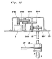
- Fig. 12 shows a drive mechanism for driving the suspended roller 78, employed in the image forming apparatus to which the method according to the second embodiment of the present invention may be applied.
- rotation of the motor 1 is transmitted to the shaft 16 through gears 98a to 98f.
- Rotational direction and rotational speed of the shaft 16 are determined by rotational direction and rotational speed of the motor 1.
- the guide 11 is displaced in the direction of the arrow I.
- the guide 11 is displaced in the direction of the arrow J.
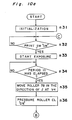
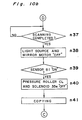
- Figs. 10a and 10b are flow charts showing a processing sequence of a copying operation of the image forming apparatus of Fig. 3 in the method according to the second embodiment of the present invention.
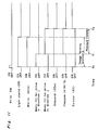
- Fig. 11 is a timing chart of the various motors, the solenoid 35e, etc. in the copying operation.
- step n37 It is found at step n37 that scanning of the original document has been completed, the light source 23 and the mirror motor for driving the mirrors 24 to 26 are turned off at step n38 so as to finish exposure. At this time, the rear end 34a-2 of the image area 34a of the photoreceptive sheet 34 is disposed just at the exposure position P1. Thus, transport of the photoreceptive sheet 34 is continued until the rear end 34a-2 of the image area 34a reaches a location spaced downstream the length ⁇ from the image forming position P2. At step n39, a decision is made as to whether or not the sensor 81 is in ON state.
- step n40 at which the motor 1 is turned off, the clutch for the upper pressure roller 32 is turned off so as to stop transport of the photoreceptive sheet 34 and the solenoid 35e for the supply shaft 35 is turned off so as to lock the supply shaft 35.
- Steps n34 to n40 correspond to the second step of Claim 4. Then, copying processing such as heating of the image receiving sheet 46a or 46b, etc. is performed at step n41 and thus, the copying operation is completed.
- the same effect as that of the first embodiment of the present invention can be achieved. Furthermore, in the second embodiment of the present invention, since image forming exposure and pressure transfer can be performed simultaneously while exposure speed and image forming speed are separately set, time period required for forming the image can be reduced.
- Figs. 13a to 13e show transport states of the photoreceptive sheet 34 in a method of controlling transport of the photoreceptive sheet 34, according to a third embodiment of the present invention. Since Figs. 13a to 13c are substantially identical with Figs. 9a to 9c, respectively, description thereof is abbreviated for the sake of brevity.
- Fig. 13d shows a state in which image formation has been completed.
- the suspended roller 78 has been returned to the original position (home position)
- exposure of the rear end 34a-2 of the image area 34a has been just completed. Therefore, the exposed photoreceptive sheet 34 disposed between the exposure position P1 and the image forming position P2 is subsequently transported continuously until the rear end 34a-2 of the image area 34a is displaced to a location slightly downstream of the image forming position P2. This is because such a phenomenon is prevented that image formation is completed in a state where the rear end of the image receiving sheet 46 is gripped between the upper and lower pressure rollers 32 and 33.
- a time period t2′ between the time point t0 and a time point of completion of exposure is employed in the third embodiment of the present invention.
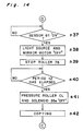
- Fig. 14 is a flow chart showing a processing sequence of a copying operation of the image forming apparatus of Fig. 3 in the method according to the third embodiment of the present invention.
- Fig. 15 is a timing chart of the various motors, the solenoid 35e, etc. in the copying operation.
- steps n31 to n36 of Fig. 10a are followed by steps n37 to n42 of Fig. 14. Since steps n31 to n36 of Fig. 10a have been described earlier, description thereof is abbreviated for the sake of brevity.
- step n37 If turning on of the sensor 81 is detected at step n37, it means that the predetermined time period t2′, i.e. the exposure time has elapsed.
- the light source 23 and the mirror motor for driving the mirrors 24 to 26 are turned off at step n38 so as to finish exposure.
- step n39 the suspended roller 78 is also stopped.
- pressure transfer is continuously performed until the photoreceptive sheet is fed through the distance l.
- pressure transfer is stopped by turning off the clutch for the upper pressure roller 32 and the solenoid 35e for the supply shaft 35 upon lapse of the time period t2, i.e. at the time when the rear end 34a-2 of the image area 34a is disposed at a location spaced downstream about 20 mm from the image forming position P2.
- copying processing such as heating of the image receiving sheet 46a or 46b, etc. is performed at step n42 and thus, the copying operation is completed.
Landscapes
- Physics & Mathematics (AREA)
- General Physics & Mathematics (AREA)
- Photographic Developing Apparatuses (AREA)
Applications Claiming Priority (6)
| Application Number | Priority Date | Filing Date | Title |
|---|---|---|---|
| JP6442688A JPH01235952A (ja) | 1988-03-16 | 1988-03-16 | 光受容シート搬送制御方法 |
| JP64427/88 | 1988-03-16 | ||
| JP6442788A JPH01235953A (ja) | 1988-03-16 | 1988-03-16 | 光受容シート搬送制御方法 |
| JP64426/88 | 1988-03-16 | ||
| JP6490188A JPH01237549A (ja) | 1988-03-17 | 1988-03-17 | 光受容シート搬送制御方法 |
| JP64901/88 | 1988-03-17 |
Publications (2)
| Publication Number | Publication Date |
|---|---|
| EP0333157A1 true EP0333157A1 (fr) | 1989-09-20 |
| EP0333157B1 EP0333157B1 (fr) | 1993-12-08 |
Family
ID=27298478
Family Applications (1)
| Application Number | Title | Priority Date | Filing Date |
|---|---|---|---|
| EP89104583A Expired - Lifetime EP0333157B1 (fr) | 1988-03-16 | 1989-03-15 | Procédé de contrôle du transport d'une feuille photoréceptive |
Country Status (3)
| Country | Link |
|---|---|
| US (1) | US4939535A (fr) |
| EP (1) | EP0333157B1 (fr) |
| DE (1) | DE68911177T2 (fr) |
Cited By (1)
| Publication number | Priority date | Publication date | Assignee | Title |
|---|---|---|---|---|
| EP0358489B1 (fr) * | 1988-09-09 | 1996-01-03 | Sharp Kabushiki Kaisha | Appareil pour la formation d'images |
Families Citing this family (2)
| Publication number | Priority date | Publication date | Assignee | Title |
|---|---|---|---|---|
| JPH03142456A (ja) * | 1989-10-30 | 1991-06-18 | Brother Ind Ltd | 画像形成装置 |
| JPH0498256A (ja) * | 1990-08-16 | 1992-03-30 | Brother Ind Ltd | 画像記録装置 |
Citations (4)
| Publication number | Priority date | Publication date | Assignee | Title |
|---|---|---|---|---|
| DE2305684A1 (de) * | 1972-02-07 | 1973-08-16 | Minolta Camera Kk | Elektrophotographisches kopiergeraet |
| DE1597879B2 (de) * | 1966-09-29 | 1976-07-08 | Rank Xerox Ltd., London | Elektrographische aufzeichnungsvorrichtung mit in einem raster angeordneten stiften zur elektrostatischen bilderzeugung |
| GB1554121A (en) * | 1976-03-25 | 1979-10-17 | Pitney Bowes Inc | Copying machines |
| US4596457A (en) * | 1984-03-30 | 1986-06-24 | Oce-Nederland B.V. | Apparatus and method for controlling electrophotographic apparatus having a photoconductive belt with a seam |
Family Cites Families (10)
| Publication number | Priority date | Publication date | Assignee | Title |
|---|---|---|---|---|
| US3533691A (en) * | 1966-10-22 | 1970-10-13 | Ricoh Kk | Electrophotographic duplicator |
| JPS5393225U (fr) * | 1976-12-28 | 1978-07-29 | ||
| DE2705181A1 (de) * | 1977-02-22 | 1978-08-10 | Nippon Electric Co | Vorrichtung zur foerderung eines aufzeichnungstraegers |
| US4260234A (en) * | 1979-06-25 | 1981-04-07 | Autologic, Inc. | Media transporter for phototypesetter-processor |
| US4399209A (en) * | 1981-11-12 | 1983-08-16 | The Mead Corporation | Transfer imaging system |
| JPS60259496A (ja) * | 1984-06-05 | 1985-12-21 | Sekisui Chem Co Ltd | 光学式情報記録体 |
| US4576891A (en) * | 1984-06-15 | 1986-03-18 | The Mead Corporation | Photosensitive microcapsules useful in polychromatic imaging having radiation absorber |
| US4624560A (en) * | 1985-10-25 | 1986-11-25 | Itt Corporation | Capsule rupture printing system |
| NL8503559A (nl) * | 1985-12-24 | 1986-04-01 | Oce Nederland Bv | Beeldvormend apparaat. |
| US4777513A (en) * | 1987-10-09 | 1988-10-11 | The Mead Corporation | Web transport system |
-
1989
- 1989-03-15 DE DE68911177T patent/DE68911177T2/de not_active Expired - Lifetime
- 1989-03-15 US US07/323,869 patent/US4939535A/en not_active Expired - Lifetime
- 1989-03-15 EP EP89104583A patent/EP0333157B1/fr not_active Expired - Lifetime
Patent Citations (4)
| Publication number | Priority date | Publication date | Assignee | Title |
|---|---|---|---|---|
| DE1597879B2 (de) * | 1966-09-29 | 1976-07-08 | Rank Xerox Ltd., London | Elektrographische aufzeichnungsvorrichtung mit in einem raster angeordneten stiften zur elektrostatischen bilderzeugung |
| DE2305684A1 (de) * | 1972-02-07 | 1973-08-16 | Minolta Camera Kk | Elektrophotographisches kopiergeraet |
| GB1554121A (en) * | 1976-03-25 | 1979-10-17 | Pitney Bowes Inc | Copying machines |
| US4596457A (en) * | 1984-03-30 | 1986-06-24 | Oce-Nederland B.V. | Apparatus and method for controlling electrophotographic apparatus having a photoconductive belt with a seam |
Cited By (1)
| Publication number | Priority date | Publication date | Assignee | Title |
|---|---|---|---|---|
| EP0358489B1 (fr) * | 1988-09-09 | 1996-01-03 | Sharp Kabushiki Kaisha | Appareil pour la formation d'images |
Also Published As
| Publication number | Publication date |
|---|---|
| EP0333157B1 (fr) | 1993-12-08 |
| DE68911177T2 (de) | 1994-06-30 |
| DE68911177D1 (de) | 1994-01-20 |
| US4939535A (en) | 1990-07-03 |
Similar Documents
| Publication | Publication Date | Title |
|---|---|---|
| US4939535A (en) | Method of controlling transport of photoreceptive sheet | |
| US6101365A (en) | Image generating apparatus with tension unit for adjusting tension of continuous paper | |
| JP2519820B2 (ja) | 平面走査画像記録装置 | |
| US5430522A (en) | Image forming apparatus with enhanced transport of its photosensitive recording member | |
| US4952968A (en) | Apparatus for the formation of images | |
| JPH01237549A (ja) | 光受容シート搬送制御方法 | |
| US4980722A (en) | Apparatus for transporting a photosensitive sheet at different speeds in accordance with the operation being performed by the machine | |
| EP0702268B1 (fr) | Appareil pour le traitement de matériaux photographiques | |
| JP2568307B2 (ja) | 感光材料供給装置 | |
| JPH01235952A (ja) | 光受容シート搬送制御方法 | |
| JPH052927Y2 (fr) | ||
| JP2546896B2 (ja) | 圧力現像装置を備えた画像形成装置 | |
| JP2808385B2 (ja) | 画像形成装置 | |
| JP2652065B2 (ja) | デカール機構及び前記デカール機構を用いた記録装置 | |
| JPH0812414B2 (ja) | バッファローラを備える画像形成装置 | |
| JP2566055B2 (ja) | バッファローラ初期制御装置 | |
| JP3711695B2 (ja) | 記録装置 | |
| JPH01235953A (ja) | 光受容シート搬送制御方法 | |
| JPH0212149A (ja) | 画像形成装置 | |
| JP3069382B2 (ja) | 転写材のカール付け装置 | |
| EP1445651A2 (fr) | Appareil d'enregistrement et de développement thermique | |
| JPH04316044A (ja) | 画像形成装置 | |
| JPH08169609A (ja) | 画像記録装置の排紙制御装置 | |
| JP2001235805A (ja) | 画像記録材料の走行経路構造 | |
| JPH041761A (ja) | 画像形成装置 |
Legal Events
| Date | Code | Title | Description |
|---|---|---|---|
| PUAI | Public reference made under article 153(3) epc to a published international application that has entered the european phase |
Free format text: ORIGINAL CODE: 0009012 |
|
| 17P | Request for examination filed |
Effective date: 19890315 |
|
| AK | Designated contracting states |
Kind code of ref document: A1 Designated state(s): DE FR GB |
|
| 17Q | First examination report despatched |
Effective date: 19920610 |
|
| GRAA | (expected) grant |
Free format text: ORIGINAL CODE: 0009210 |
|
| AK | Designated contracting states |
Kind code of ref document: B1 Designated state(s): DE FR GB |
|
| REF | Corresponds to: |
Ref document number: 68911177 Country of ref document: DE Date of ref document: 19940120 |
|
| ET | Fr: translation filed | ||
| K2C2 | Correction of patent specification (partial reprint) published |
Effective date: 19931208 |
|
| PLBE | No opposition filed within time limit |
Free format text: ORIGINAL CODE: 0009261 |
|
| STAA | Information on the status of an ep patent application or granted ep patent |
Free format text: STATUS: NO OPPOSITION FILED WITHIN TIME LIMIT |
|
| 26N | No opposition filed | ||
| REG | Reference to a national code |
Ref country code: GB Ref legal event code: IF02 |
|
| PGFP | Annual fee paid to national office [announced via postgrant information from national office to epo] |
Ref country code: GB Payment date: 20080312 Year of fee payment: 20 |
|
| PGFP | Annual fee paid to national office [announced via postgrant information from national office to epo] |
Ref country code: DE Payment date: 20080313 Year of fee payment: 20 Ref country code: FR Payment date: 20080311 Year of fee payment: 20 |
|
| REG | Reference to a national code |
Ref country code: GB Ref legal event code: PE20 Expiry date: 20090314 |
|
| PG25 | Lapsed in a contracting state [announced via postgrant information from national office to epo] |
Ref country code: GB Free format text: LAPSE BECAUSE OF EXPIRATION OF PROTECTION Effective date: 20090314 |