EP0334044A2 - Système de contrôle pour empêcher la collision de deux couteaux - Google Patents
Système de contrôle pour empêcher la collision de deux couteaux Download PDFInfo
- Publication number
- EP0334044A2 EP0334044A2 EP89103132A EP89103132A EP0334044A2 EP 0334044 A2 EP0334044 A2 EP 0334044A2 EP 89103132 A EP89103132 A EP 89103132A EP 89103132 A EP89103132 A EP 89103132A EP 0334044 A2 EP0334044 A2 EP 0334044A2
- Authority
- EP
- European Patent Office
- Prior art keywords
- cutting
- collision
- comparator
- register
- computer
- Prior art date
- Legal status (The legal status is an assumption and is not a legal conclusion. Google has not performed a legal analysis and makes no representation as to the accuracy of the status listed.)
- Granted
Links
Images



Classifications
-
- C—CHEMISTRY; METALLURGY
- C14—SKINS; HIDES; PELTS; LEATHER
- C14B—MECHANICAL TREATMENT OR PROCESSING OF SKINS, HIDES OR LEATHER IN GENERAL; PELT-SHEARING MACHINES; INTESTINE-SPLITTING MACHINES
- C14B5/00—Clicking, perforating, or cutting leather
-
- B—PERFORMING OPERATIONS; TRANSPORTING
- B26—HAND CUTTING TOOLS; CUTTING; SEVERING
- B26D—CUTTING; DETAILS COMMON TO MACHINES FOR PERFORATING, PUNCHING, CUTTING-OUT, STAMPING-OUT OR SEVERING
- B26D7/00—Details of apparatus for cutting, cutting-out, stamping-out, punching, perforating, or severing by means other than cutting
- B26D7/22—Safety devices specially adapted for cutting machines
- B26D7/24—Safety devices specially adapted for cutting machines arranged to disable the operating means for the cutting member
-
- B—PERFORMING OPERATIONS; TRANSPORTING
- B26—HAND CUTTING TOOLS; CUTTING; SEVERING
- B26F—PERFORATING; PUNCHING; CUTTING-OUT; STAMPING-OUT; SEVERING BY MEANS OTHER THAN CUTTING
- B26F3/00—Severing by means other than cutting; Apparatus therefor
- B26F3/004—Severing by means other than cutting; Apparatus therefor by means of a fluid jet
-
- G—PHYSICS
- G05—CONTROLLING; REGULATING
- G05B—CONTROL OR REGULATING SYSTEMS IN GENERAL; FUNCTIONAL ELEMENTS OF SUCH SYSTEMS; MONITORING OR TESTING ARRANGEMENTS FOR SUCH SYSTEMS OR ELEMENTS
- G05B19/00—Program-control systems
- G05B19/02—Program-control systems electric
- G05B19/18—Numerical control [NC], i.e. automatically operating machines, in particular machine tools, e.g. in a manufacturing environment, so as to execute positioning, movement or co-ordinated operations by means of program data in numerical form
- G05B19/406—Numerical control [NC], i.e. automatically operating machines, in particular machine tools, e.g. in a manufacturing environment, so as to execute positioning, movement or co-ordinated operations by means of program data in numerical form characterised by monitoring or safety
- G05B19/4065—Monitoring tool breakage, life or condition
-
- G—PHYSICS
- G05—CONTROLLING; REGULATING
- G05B—CONTROL OR REGULATING SYSTEMS IN GENERAL; FUNCTIONAL ELEMENTS OF SUCH SYSTEMS; MONITORING OR TESTING ARRANGEMENTS FOR SUCH SYSTEMS OR ELEMENTS
- G05B2219/00—Program-control systems
- G05B2219/30—Nc systems
- G05B2219/49—Nc machine tool, till multiple
- G05B2219/49153—Avoid collision, interference between tools moving along same axis
-
- Y—GENERAL TAGGING OF NEW TECHNOLOGICAL DEVELOPMENTS; GENERAL TAGGING OF CROSS-SECTIONAL TECHNOLOGIES SPANNING OVER SEVERAL SECTIONS OF THE IPC; TECHNICAL SUBJECTS COVERED BY FORMER USPC CROSS-REFERENCE ART COLLECTIONS [XRACs] AND DIGESTS
- Y10—TECHNICAL SUBJECTS COVERED BY FORMER USPC
- Y10S—TECHNICAL SUBJECTS COVERED BY FORMER USPC CROSS-REFERENCE ART COLLECTIONS [XRACs] AND DIGESTS
- Y10S83/00—Cutting
- Y10S83/929—Particular nature of work or product
- Y10S83/936—Cloth or leather
- Y10S83/939—Cloth or leather with work support
- Y10S83/94—Cutter moves along bar, bar moves perpendicularly
-
- Y—GENERAL TAGGING OF NEW TECHNOLOGICAL DEVELOPMENTS; GENERAL TAGGING OF CROSS-SECTIONAL TECHNOLOGIES SPANNING OVER SEVERAL SECTIONS OF THE IPC; TECHNICAL SUBJECTS COVERED BY FORMER USPC CROSS-REFERENCE ART COLLECTIONS [XRACs] AND DIGESTS
- Y10—TECHNICAL SUBJECTS COVERED BY FORMER USPC
- Y10T—TECHNICAL SUBJECTS COVERED BY FORMER US CLASSIFICATION
- Y10T83/00—Cutting
- Y10T83/081—With randomly actuated stopping means
- Y10T83/088—Responsive to tool detector or work-feed-means detector
- Y10T83/089—Responsive to tool characteristic
-
- Y—GENERAL TAGGING OF NEW TECHNOLOGICAL DEVELOPMENTS; GENERAL TAGGING OF CROSS-SECTIONAL TECHNOLOGIES SPANNING OVER SEVERAL SECTIONS OF THE IPC; TECHNICAL SUBJECTS COVERED BY FORMER USPC CROSS-REFERENCE ART COLLECTIONS [XRACs] AND DIGESTS
- Y10—TECHNICAL SUBJECTS COVERED BY FORMER USPC
- Y10T—TECHNICAL SUBJECTS COVERED BY FORMER US CLASSIFICATION
- Y10T83/00—Cutting
- Y10T83/141—With means to monitor and control operation [e.g., self-regulating means]
- Y10T83/148—Including means to correct the sensed operation
-
- Y—GENERAL TAGGING OF NEW TECHNOLOGICAL DEVELOPMENTS; GENERAL TAGGING OF CROSS-SECTIONAL TECHNOLOGIES SPANNING OVER SEVERAL SECTIONS OF THE IPC; TECHNICAL SUBJECTS COVERED BY FORMER USPC CROSS-REFERENCE ART COLLECTIONS [XRACs] AND DIGESTS
- Y10—TECHNICAL SUBJECTS COVERED BY FORMER USPC
- Y10T—TECHNICAL SUBJECTS COVERED BY FORMER US CLASSIFICATION
- Y10T83/00—Cutting
- Y10T83/364—By fluid blast and/or suction
-
- Y—GENERAL TAGGING OF NEW TECHNOLOGICAL DEVELOPMENTS; GENERAL TAGGING OF CROSS-SECTIONAL TECHNOLOGIES SPANNING OVER SEVERAL SECTIONS OF THE IPC; TECHNICAL SUBJECTS COVERED BY FORMER USPC CROSS-REFERENCE ART COLLECTIONS [XRACs] AND DIGESTS
- Y10—TECHNICAL SUBJECTS COVERED BY FORMER USPC
- Y10T—TECHNICAL SUBJECTS COVERED BY FORMER US CLASSIFICATION
- Y10T83/00—Cutting
- Y10T83/869—Means to drive or to guide tool
- Y10T83/8691—Unicyclic
- Y10T83/8694—With brake or blocking means
Definitions
- the invention relates to a device for preventing collisions between two cutting tools to be moved towards one another in a computer-controlled cutting system.
- DE-OS 33 21 954 discloses an ultra-high pressure water jet cutting system with a cutting device which is formed from a cutting portal and a cutting head carrier arranged thereon.
- the contours to be cut out of the material by the high-pressure nozzle arranged in the cutting head carrier are manually entered in the form of data pairs into a computer connected to the cutting device and then individually traversed with the high-pressure nozzle open.
- two cutting tools are used, they can be arranged in such a way that they start moving towards each other from the outer edge of the cutting table of the cutting system, starting with the cut, and both pass half of the intended cutting lines in the longitudinal and transverse dimensions.
- the cutting time can only be reduced by exactly the factor of the number of cutting tools used in comparison to a single one, if the cutting is symmetrical to the line on which the start or end point of the individual cutting tools lies.
- the time reduction depends solely on the contours of the individual patterns to be cut out.
- the division of the cutting order of the individual contours to be cut out must be carried out from a possible collision point of view.
- the set of coordinates of each cutting contour is entered into the arithmetic unit.
- a safety zone describing the tolerated approach is assigned to each possible or necessary movement in the direction at risk of collision. This safety zone is a constant amount that is added or subtracted to the respective position coordinate.
- the invention has for its object to provide a device for collision prevention of several cutting tools of a computer-controlled cutting system.
- An advantage of the invention is that the actual position of each cutting tool is always monitored and a collision risk caused by different dynamic conditions is prevented.
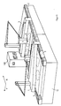
- Two cutting portals 1, 2 on racks 4, 5 are arranged longitudinally displaceably on the machine frame 12 above the cutting table 3, whereby the complete longitudinal extent of the material to be spread out on the cutting table can be traveled over by each cutting portal 1, 2.
- Each cutting portal 1, 2 carries a cutting head carrier 6 and 7, which is mounted on the cross-slide and receives the high-pressure cutting nozzles I and II.
- the storage of the cutting portals 1,2 and the cutting head support 6,7 can be carried out in the form known from DE-PS 36 37 617.
- the actual value of the distance traveled for each portal 1 or 2 is determined using incremental displacement sensors. These displacement sensors are connected in a known manner to the respective motor of portals 1, 2.
- the displacement transducers are designated W1, W2, displacement transducers W1 being assigned to the cutting portal 1 and displacement transducers W2 to the cutting portal 2.
- This indexing also applies to the motors M1 and M2, which are only shown symbolically, and the electronic functional units NC1 and NC2, which will be explained in more detail below. It goes without saying that the displacement transducers W1, W2 connected to the motors M1 and M2 do not necessarily have to work incrementally, but an absolute displacement measurement would also be conceivable.
- the position controllers SX1 and SY1 for the longitudinal and transverse movement of the cutting portal 1 are connected on the one hand to the electronic functional unit NC1 and on the other hand to the drive motor provided for the corresponding direction of movement, the cutting portal 1 of course only moving in the longitudinal direction (x direction) and the cross direction (y direction) is only traversed by the cutter holder 6.
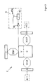
- the drive motors M1, M2 of the cutting portals 1, 2 with the associated displacement sensors W1 are shown in FIG , W2 shown.
- the position controllers SY1, SY2, which are responsible for the transverse movement of the cutting head carriers 6, 7, are also operatively connected to corresponding motors and displacement sensors.
- the functional units NC1, NC2 consist of an autonomously working computer system with a Z80 main processor with program and working memories.
- Each of these functional units is responsible for controlling a cutting portal.
- the management computer VR consists of a central computer with keyboard and screen as well as a program memory (EPROM) and a working memory (CMOS-RAM).
- the programmable logic controller PLC also has a Z80 microprocessor and is used to operate actuators.
- the commands for opening or closing the high-pressure nozzles I and / or II come from it, for example.
- a time analysis provides the result that with simultaneous path control of 2-axis pairs at a maximum speed of 1 m / s and a required accuracy of 0.1 mm, for example, a system response time which is less than 100 ⁇ s is required.
- the diagram of a hierarchical system structure shown here enables such low response times, since each function group PLC, NC1, NC2, independently of the others, processes the tasks assigned to it and then receives new tasks or commands from the management computer VR.
- VME-BUS Known bus structures with a multi-task real-time operating system ensure fast communication with your management computer VR.
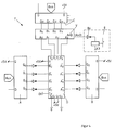
- next target coordinate P 1 (x) is written in the collision-prone direction (x direction) of the cutting portal 1 in the register A of the functional unit F and stored for a short time.
- the functional unit NC2 writes the next target coordinate P2 (x) of the cutting portal 2 in the register B of the functional unit F, this value also being stored briefly.
- a difference generator D in the functional unit F the values from the registers A and B are subtracted in accordance with the above equation and the difference is compared in a comparator V with the value of the register C.
- FIG. 4 shows the circuit of the functional unit F described above, only a 4-bit circuit being shown for reasons of simplification, but which can be expanded to 32 bits by simple multiplication.
- the numbers drawn into the component groups indicate the inputs and outputs known to the person skilled in the art.
- the registers A, B, C can each consist of "two 4-bit latches” (for example 74 100), the difference generator D each of "4-bit arithmetic-logic unit” (for example 74 181) and the comparator V each a "4-bit comparator” (for example 7485).
- the actuator 8 consists in a known manner of an amplifier 8a, a contactor K3 connected in series and the associated switch K3a.
- FIG. 5 the circuit diagram of an electrical circuit that fulfills this condition is described by way of example.
- An acknowledgment switch with TA, a so-called crash switch with CS and the contactors with K1-K3 are designated here.
- This circuit works as follows: To switch on the cutting system, the switch TA is actuated, so that the contactor K1 picks up and the associated switches K1a, K1b close. As a result, the contactor K2 picks up and the switches K2a, K2d, K2e, K2f close while the switches K2b, K2c open.
- the contactor K1 is thus de-energized again and the switches K1a, K1b open.
- the safety circuit is now activated and the position controllers SX1, SX2 are ready for operation, the cutting process can begin - provided the corresponding control commands are sent to the position controllers SX1, SX2.
- the control pulse is sent from the comparator V, which is passed on via the amplifier 8a and the line 9 to the contactor K3, which then picks up and the associated switch K3a opens.
- the connection to the position controllers SX1 and / or SX2 is interrupted, as a result of which their power output is de-energized and the motors M1, M2 of the cutting portals 1, 2 stop.
- the switches K2a, K2d, K2e, K2f are opened and the switches K2b, K2c are closed because the contactor K2 has been switched off.
- the motors M1, M2 are braked by means of the schematically illustrated brakes 10, 11. If the acknowledgment switch TA is designed as a button, it is ensured that this must always be actuated in order to start a new cutting process after an automatic shutdown. This also ensures, for example, that if an impending collision has been determined in comparator V, the operator must in each case decide whether a further cutting process is possible or not.
- crash switch CS is a mechanical safeguard against a collision.
- This switch CS is arranged on one of the portals 1 or 2 and a sensor or a rod (not shown in more detail) is attached to the corresponding point of the other portal, the length of which corresponds to the tolerated approach of portals 1 and 2. If this distance is undershot and no comparator V sends a control pulse to the actuator K3, the sensor actuates the switch CS, so that the circuit to the position controllers SX1 and SX2 is interrupted.
- the cutting nozzles I, II should be switched off and moved into a safe position in order to avoid additional damage.
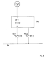
- the crash switch CS is electrically connected to the programmable logic controller PLC. From Figures 5 and 6 it is clear that the programmable logic controller PLC receives an electrical pulse in the event of a collision so that a computer program can run, with the result that the magnetic switches MS1, MS2 of the cutting nozzle I, II are controlled and, on the one hand, the Turn off nozzles I and II and move them advantageously to a higher position.
Landscapes
- Engineering & Computer Science (AREA)
- Mechanical Engineering (AREA)
- Life Sciences & Earth Sciences (AREA)
- Forests & Forestry (AREA)
- Human Computer Interaction (AREA)
- Organic Chemistry (AREA)
- Chemical & Material Sciences (AREA)
- Manufacturing & Machinery (AREA)
- Physics & Mathematics (AREA)
- General Physics & Mathematics (AREA)
- Automation & Control Theory (AREA)
- Numerical Control (AREA)
- Perforating, Stamping-Out Or Severing By Means Other Than Cutting (AREA)
- Details Of Cutting Devices (AREA)
- Auxiliary Devices For Machine Tools (AREA)
Applications Claiming Priority (2)
| Application Number | Priority Date | Filing Date | Title |
|---|---|---|---|
| DE3809630A DE3809630C1 (fr) | 1988-03-22 | 1988-03-22 | |
| DE3809630 | 1989-03-22 |
Publications (3)
| Publication Number | Publication Date |
|---|---|
| EP0334044A2 true EP0334044A2 (fr) | 1989-09-27 |
| EP0334044A3 EP0334044A3 (fr) | 1991-01-30 |
| EP0334044B1 EP0334044B1 (fr) | 1994-04-27 |
Family
ID=6350389
Family Applications (1)
| Application Number | Title | Priority Date | Filing Date |
|---|---|---|---|
| EP89103132A Expired - Lifetime EP0334044B1 (fr) | 1988-03-22 | 1989-02-23 | Système de contrôle pour empêcher la collision de deux couteaux |
Country Status (7)
| Country | Link |
|---|---|
| US (1) | US4994979A (fr) |
| EP (1) | EP0334044B1 (fr) |
| JP (1) | JP2676627B2 (fr) |
| DD (1) | DD283578A5 (fr) |
| DE (2) | DE3809630C1 (fr) |
| ES (1) | ES2051902T3 (fr) |
| SU (1) | SU1644714A3 (fr) |
Cited By (2)
| Publication number | Priority date | Publication date | Assignee | Title |
|---|---|---|---|---|
| EP0716362A3 (fr) * | 1994-12-08 | 1996-08-14 | Index Werke Kg Hahn & Tessky | Méthode et dispositif de surveillance du déplacement d'une partie d'une machine-outil |
| DE19516047A1 (de) * | 1995-05-04 | 1996-11-07 | Wohlenberg Vertriebs Und Servi | Dreischneider |
Families Citing this family (14)
| Publication number | Priority date | Publication date | Assignee | Title |
|---|---|---|---|---|
| US5304906A (en) * | 1989-12-26 | 1994-04-19 | Fanuc Ltd. | Collision detecting method using an observer |
| DE4039827C2 (de) * | 1990-12-13 | 1995-04-06 | Duerkopp System Technik Gmbh | Vorrichtung zum Einstellen des parallelen Abstands von Werkzeugen an einer numerisch gesteuerten Werkzeugmaschine |
| FR2722618B1 (fr) * | 1994-07-13 | 1996-08-14 | Sylea Sa | Installation pour la distribution de patons de matiere adhesive plastique et outil pour la pose desdits patons dans des elements de boitiers de connecteurs electriques |
| US5798627A (en) * | 1995-01-04 | 1998-08-25 | Gilliland; Malcolm T. | Method for simultaneous operation of robot welders |
| US5727433A (en) * | 1995-09-08 | 1998-03-17 | Gerber Garment Technology, Inc. | Method for cutting sheet material |
| DE19719196C2 (de) * | 1996-05-08 | 2000-06-29 | Wolfgang Bruder | Verfahren und Vorrichtung zur Herstellung von Zuschnitten aus fehlerhaften, flächigen biegeschlaffen Werkstoffen |
| US5806719A (en) * | 1997-07-11 | 1998-09-15 | Tetra Laval Holdings & Finance, Sa | Fitment based dispensing system for a pouch |
| US6520057B1 (en) * | 1997-09-30 | 2003-02-18 | Eastman Machine Company | Continuous system and method for cutting sheet material |
| IT1305391B1 (it) * | 1998-09-11 | 2001-05-04 | Teseo Spa | Macchina perfezionata per il taglio di pelli e simili |
| EP1067200A1 (fr) * | 1999-07-02 | 2001-01-10 | Gerhard Winter | Machine-outil à découper en continu des éléments en forme de feuilles, en particulier des peaux et analogue |
| ITBO20010134A1 (it) * | 2001-03-13 | 2002-09-13 | Jobs Spa | Macchina utensile |
| US20060096437A1 (en) * | 2004-11-08 | 2006-05-11 | Billco Manufacturing, Inc. | Integrated glass cutting and laser marking table |
| DE102010016479A1 (de) * | 2010-04-16 | 2011-10-20 | Matthias Felber | Schneidemaschine und Verfahren zur Durchführung von Schneidearbeiten an flächigen biegeschlaffen oder sonstigen Materialien |
| DE102014218977A1 (de) * | 2014-09-22 | 2016-03-24 | Bayerische Motoren Werke Aktiengesellschaft | Verfahren für den Zuschnitt von Halbzeugstreifen und Schneidvorrichtung für den Zuschnitt von Halbzeugstreifen |
Family Cites Families (16)
| Publication number | Priority date | Publication date | Assignee | Title |
|---|---|---|---|---|
| US2809541A (en) * | 1953-11-16 | 1957-10-15 | Remington Arms Co Inc | Obstruction detector for heading machine |
| US3626796A (en) * | 1970-04-01 | 1971-12-14 | Gerber Garment Technology Inc | Sheet material cutting apparatus with fail-safe means |
| US3769488A (en) * | 1972-01-19 | 1973-10-30 | Hughes Aircraft Co | Workload allocation for one or more tools in a laser cloth cutting system |
| JPS5333484A (en) * | 1976-09-10 | 1978-03-29 | Okuma Mach Works Ltd | Interference preventive system of machine tool having plurality of movable members |
| US4267914A (en) * | 1979-04-26 | 1981-05-19 | Black & Decker Inc. | Anti-kickback power tool control |
| US4442493A (en) * | 1980-07-04 | 1984-04-10 | Kabushiki Kaisha Komatsu Seisakusho | Cutting tool retreat and return for workpiece protection upon abnormality occurrence in a preprogrammed machine tool |
| US4471676A (en) * | 1981-02-23 | 1984-09-18 | Joseph Rhodes Limited | Machine tool including workpiece clamp sensor |
| US4463639A (en) * | 1982-06-22 | 1984-08-07 | Gerber Garment Technology, Inc. | Fluid jet receiver positioner |
| US4489377A (en) * | 1982-09-07 | 1984-12-18 | General Electric Company | Method for preventing machine component interference |
| JPS60247421A (ja) * | 1984-05-24 | 1985-12-07 | Fanuc Ltd | タレツトパンチプレス用数値制御におけるワ−クホルダと工具との衝突防止装置 |
| DE3527063C1 (de) * | 1985-07-27 | 1986-01-30 | Fa. Carl Zeiss, 7920 Heidenheim | Verfahren und Vorrichtung zum Schutz eines beweglichen,langgestreckten Maschinenteils |
| JPS6238905A (ja) * | 1985-08-15 | 1987-02-19 | Mitsubishi Electric Corp | 数値制御装置 |
| DE3544251A1 (de) * | 1985-12-14 | 1987-06-19 | Duerkopp System Technik Gmbh | Verfahren und vorrichtung zum selbsttaetigen zuschneiden von teilen aus flaechigem naehgut nach mit unterschiedlichen konturen versehenen mustervorlagen auf einer koordinaten-schneidmaschine |
| US4758961A (en) * | 1986-07-10 | 1988-07-19 | Yamazaki Machinery Works, Ltd. | Tool move control method and apparatus for preventing tool interference with an object. |
| DE3627110A1 (de) * | 1986-08-06 | 1988-02-18 | Duerkopp System Technik Gmbh | Verfahren und vorrichtung zur optimierung eines materialzuschnittes |
| US4736661A (en) * | 1986-09-22 | 1988-04-12 | Takaaki Shirai | Cutting apparatus |
-
1988
- 1988-03-22 DE DE3809630A patent/DE3809630C1/de not_active Expired
-
1989
- 1989-02-23 ES ES89103132T patent/ES2051902T3/es not_active Expired - Lifetime
- 1989-02-23 DE DE58907540T patent/DE58907540D1/de not_active Expired - Lifetime
- 1989-02-23 EP EP89103132A patent/EP0334044B1/fr not_active Expired - Lifetime
- 1989-03-15 JP JP1061098A patent/JP2676627B2/ja not_active Expired - Fee Related
- 1989-03-20 DD DD89326754A patent/DD283578A5/de not_active IP Right Cessation
- 1989-03-21 SU SU894613765A patent/SU1644714A3/ru active
- 1989-03-22 US US07/327,301 patent/US4994979A/en not_active Expired - Fee Related
Cited By (2)
| Publication number | Priority date | Publication date | Assignee | Title |
|---|---|---|---|---|
| EP0716362A3 (fr) * | 1994-12-08 | 1996-08-14 | Index Werke Kg Hahn & Tessky | Méthode et dispositif de surveillance du déplacement d'une partie d'une machine-outil |
| DE19516047A1 (de) * | 1995-05-04 | 1996-11-07 | Wohlenberg Vertriebs Und Servi | Dreischneider |
Also Published As
| Publication number | Publication date |
|---|---|
| EP0334044A3 (fr) | 1991-01-30 |
| SU1644714A3 (ru) | 1991-04-23 |
| ES2051902T3 (es) | 1994-07-01 |
| DE58907540D1 (de) | 1994-06-01 |
| EP0334044B1 (fr) | 1994-04-27 |
| US4994979A (en) | 1991-02-19 |
| DD283578A5 (de) | 1990-10-17 |
| JPH01274997A (ja) | 1989-11-02 |
| DE3809630C1 (fr) | 1989-05-18 |
| JP2676627B2 (ja) | 1997-11-17 |
Similar Documents
| Publication | Publication Date | Title |
|---|---|---|
| EP0334044B1 (fr) | Système de contrôle pour empêcher la collision de deux couteaux | |
| EP2008752A1 (fr) | Machine destinée au traitement de pièces à usiner et procédé destiné au traitement mécanique de pièces à usiner | |
| EP2515193B1 (fr) | Procédé destiné à éviter une collision non désirée entre un outil et une pièce usinée dans une machine-outil | |
| EP0346505B2 (fr) | Méthode de découpage de copeaux pendant le tournage des pièces à usiner | |
| EP0716362B1 (fr) | Méthode et dispositif de surveillance du déplacement d'une partie d'une machine-outil | |
| EP0789182A1 (fr) | Dispositif de sécurité dans une machine-outil à main, notamment d'une presse plieuse | |
| DE2759083A1 (de) | Profilstahlbearbeitungsanlage | |
| EP2172301A1 (fr) | Machine et procédé destinés au traitement de pièces à usiner longitudinales | |
| DE10039970B4 (de) | Bearbeitungszentrum und Verfahren zum Bearbeiten von mehreren Werkstücken | |
| WO2009146716A1 (fr) | Procédé et ensemble mécanique pour usiner des pièces d’œuvre, en particulier des tôles | |
| EP0304928A1 (fr) | Système de réglage, en particulier pour une machine-outil | |
| EP0324117B1 (fr) | Méthode pour commander le positionnement du poinçon dans une machine à poinçonner | |
| DE1966793B2 (de) | Numerische Steuereinrichtung für eine mehrachsig arbeitende Werkzeugmaschine | |
| DE3530783A1 (de) | Kombinierte anlage fuer die elektroerosion mittels draht und werkzeug | |
| EP2310167B1 (fr) | Procédé de commande du manipulateur de pièce d'une machine-outil après une interruption du processus d'usinage | |
| EP3515621A1 (fr) | Outil et machine-outil et procédé de traitement de pièces en forme de plaques | |
| DE2646179C3 (de) | Vorrichtung zum selbsttätigen Steuern eines in zwei zueinander senkrechten Richtungen verschiebbaren Werkzeugschlittens | |
| EP0743579A2 (fr) | Procédé de commande d'une machine outil à commande numérique ou d'un robot | |
| EP2939756B1 (fr) | Machine-outil de traitement d'une pièce à usiner avec un dispositif de changement d'outil et un magasin d'outils ainsi que procédé de mise en oeuvre et programme de fonctionnement d'une telle machine-outil | |
| DE202007018545U1 (de) | Maschine zum Bearbeiten von Werkstücken zum maschinellen Bearbeiten von Werkstücken | |
| EP3208033A2 (fr) | Commande d'un dispositif destiné à usiner une pièce de grande taille | |
| DE4022706C2 (de) | Drehmaschine | |
| DE3877551T2 (de) | Verfahren und vorrichtung zum positionieren und verriegeln einer von einem support getragenen einrichtung mit hilfe eines blocks. | |
| DE2264238A1 (de) | Einrichtung an werkzeugmaschinen mit kraftbetaetigten werkzeugschlitten | |
| EP0527248B1 (fr) | Système de commande de machine-outils pour l'usinage de pièces planes |
Legal Events
| Date | Code | Title | Description |
|---|---|---|---|
| PUAI | Public reference made under article 153(3) epc to a published international application that has entered the european phase |
Free format text: ORIGINAL CODE: 0009012 |
|
| AK | Designated contracting states |
Kind code of ref document: A2 Designated state(s): CH DE ES FR GB IT LI |
|
| PUAL | Search report despatched |
Free format text: ORIGINAL CODE: 0009013 |
|
| AK | Designated contracting states |
Kind code of ref document: A3 Designated state(s): CH DE ES FR GB IT LI |
|
| 17P | Request for examination filed |
Effective date: 19910531 |
|
| 17Q | First examination report despatched |
Effective date: 19930402 |
|
| GRAA | (expected) grant |
Free format text: ORIGINAL CODE: 0009210 |
|
| AK | Designated contracting states |
Kind code of ref document: B1 Designated state(s): CH DE ES FR GB IT LI |
|
| REF | Corresponds to: |
Ref document number: 58907540 Country of ref document: DE Date of ref document: 19940601 |
|
| REG | Reference to a national code |
Ref country code: ES Ref legal event code: FG2A Ref document number: 2051902 Country of ref document: ES Kind code of ref document: T3 |
|
| ITF | It: translation for a ep patent filed | ||
| ET | Fr: translation filed | ||
| GBT | Gb: translation of ep patent filed (gb section 77(6)(a)/1977) |
Effective date: 19940804 |
|
| PLBE | No opposition filed within time limit |
Free format text: ORIGINAL CODE: 0009261 |
|
| STAA | Information on the status of an ep patent application or granted ep patent |
Free format text: STATUS: NO OPPOSITION FILED WITHIN TIME LIMIT |
|
| 26N | No opposition filed | ||
| PGFP | Annual fee paid to national office [announced via postgrant information from national office to epo] |
Ref country code: FR Payment date: 19990126 Year of fee payment: 11 |
|
| PGFP | Annual fee paid to national office [announced via postgrant information from national office to epo] |
Ref country code: ES Payment date: 19990205 Year of fee payment: 11 |
|
| PGFP | Annual fee paid to national office [announced via postgrant information from national office to epo] |
Ref country code: GB Payment date: 19990218 Year of fee payment: 11 |
|
| PGFP | Annual fee paid to national office [announced via postgrant information from national office to epo] |
Ref country code: CH Payment date: 19990219 Year of fee payment: 11 |
|
| PG25 | Lapsed in a contracting state [announced via postgrant information from national office to epo] |
Ref country code: GB Free format text: LAPSE BECAUSE OF NON-PAYMENT OF DUE FEES Effective date: 20000223 |
|
| PG25 | Lapsed in a contracting state [announced via postgrant information from national office to epo] |
Ref country code: ES Free format text: LAPSE BECAUSE OF NON-PAYMENT OF DUE FEES Effective date: 20000224 |
|
| PG25 | Lapsed in a contracting state [announced via postgrant information from national office to epo] |
Ref country code: LI Free format text: LAPSE BECAUSE OF NON-PAYMENT OF DUE FEES Effective date: 20000229 Ref country code: CH Free format text: LAPSE BECAUSE OF NON-PAYMENT OF DUE FEES Effective date: 20000229 |
|
| GBPC | Gb: european patent ceased through non-payment of renewal fee |
Effective date: 20000223 |
|
| REG | Reference to a national code |
Ref country code: CH Ref legal event code: PL |
|
| PG25 | Lapsed in a contracting state [announced via postgrant information from national office to epo] |
Ref country code: FR Free format text: LAPSE BECAUSE OF NON-PAYMENT OF DUE FEES Effective date: 20001031 |
|
| REG | Reference to a national code |
Ref country code: FR Ref legal event code: ST |
|
| REG | Reference to a national code |
Ref country code: ES Ref legal event code: FD2A Effective date: 20010910 |
|
| PGFP | Annual fee paid to national office [announced via postgrant information from national office to epo] |
Ref country code: IT Payment date: 20080227 Year of fee payment: 20 |
|
| PGFP | Annual fee paid to national office [announced via postgrant information from national office to epo] |
Ref country code: DE Payment date: 20080423 Year of fee payment: 20 |