EP0335224A2 - Verfahren zur Strahlungsthermometrie - Google Patents
Verfahren zur Strahlungsthermometrie Download PDFInfo
- Publication number
- EP0335224A2 EP0335224A2 EP89104999A EP89104999A EP0335224A2 EP 0335224 A2 EP0335224 A2 EP 0335224A2 EP 89104999 A EP89104999 A EP 89104999A EP 89104999 A EP89104999 A EP 89104999A EP 0335224 A2 EP0335224 A2 EP 0335224A2
- Authority
- EP
- European Patent Office
- Prior art keywords
- target material
- temperature
- emissivities
- radiances
- spectral
- Prior art date
- Legal status (The legal status is an assumption and is not a legal conclusion. Google has not performed a legal analysis and makes no representation as to the accuracy of the status listed.)
- Granted
Links
Images




Classifications
-
- G—PHYSICS
- G01—MEASURING; TESTING
- G01J—MEASUREMENT OF INTENSITY, VELOCITY, SPECTRAL CONTENT, POLARISATION, PHASE OR PULSE CHARACTERISTICS OF INFRARED, VISIBLE OR ULTRAVIOLET LIGHT; COLORIMETRY; RADIATION PYROMETRY
- G01J5/00—Radiation pyrometry, e.g. infrared or optical thermometry
- G01J5/02—Constructional details
- G01J5/06—Arrangements for eliminating effects of disturbing radiation; Arrangements for compensating changes in sensitivity
-
- G—PHYSICS
- G01—MEASURING; TESTING
- G01J—MEASUREMENT OF INTENSITY, VELOCITY, SPECTRAL CONTENT, POLARISATION, PHASE OR PULSE CHARACTERISTICS OF INFRARED, VISIBLE OR ULTRAVIOLET LIGHT; COLORIMETRY; RADIATION PYROMETRY
- G01J5/00—Radiation pyrometry, e.g. infrared or optical thermometry
- G01J5/0037—Radiation pyrometry, e.g. infrared or optical thermometry for sensing the heat emitted by liquids
- G01J5/004—Radiation pyrometry, e.g. infrared or optical thermometry for sensing the heat emitted by liquids by molten metals
-
- G—PHYSICS
- G01—MEASURING; TESTING
- G01J—MEASUREMENT OF INTENSITY, VELOCITY, SPECTRAL CONTENT, POLARISATION, PHASE OR PULSE CHARACTERISTICS OF INFRARED, VISIBLE OR ULTRAVIOLET LIGHT; COLORIMETRY; RADIATION PYROMETRY
- G01J5/00—Radiation pyrometry, e.g. infrared or optical thermometry
- G01J5/0044—Furnaces, ovens, kilns
-
- G—PHYSICS
- G01—MEASURING; TESTING
- G01J—MEASUREMENT OF INTENSITY, VELOCITY, SPECTRAL CONTENT, POLARISATION, PHASE OR PULSE CHARACTERISTICS OF INFRARED, VISIBLE OR ULTRAVIOLET LIGHT; COLORIMETRY; RADIATION PYROMETRY
- G01J5/00—Radiation pyrometry, e.g. infrared or optical thermometry
- G01J5/02—Constructional details
- G01J5/026—Control of working procedures of a pyrometer, other than calibration; Bandwidth calculation; Gain control
-
- G—PHYSICS
- G01—MEASURING; TESTING
- G01J—MEASUREMENT OF INTENSITY, VELOCITY, SPECTRAL CONTENT, POLARISATION, PHASE OR PULSE CHARACTERISTICS OF INFRARED, VISIBLE OR ULTRAVIOLET LIGHT; COLORIMETRY; RADIATION PYROMETRY
- G01J5/00—Radiation pyrometry, e.g. infrared or optical thermometry
- G01J5/02—Constructional details
- G01J5/0275—Control or determination of height or distance or angle information for sensors or receivers
-
- G—PHYSICS
- G01—MEASURING; TESTING
- G01J—MEASUREMENT OF INTENSITY, VELOCITY, SPECTRAL CONTENT, POLARISATION, PHASE OR PULSE CHARACTERISTICS OF INFRARED, VISIBLE OR ULTRAVIOLET LIGHT; COLORIMETRY; RADIATION PYROMETRY
- G01J5/00—Radiation pyrometry, e.g. infrared or optical thermometry
- G01J5/02—Constructional details
- G01J5/05—Means for preventing contamination of the components of the optical system; Means for preventing obstruction of the radiation path
-
- G—PHYSICS
- G01—MEASURING; TESTING
- G01J—MEASUREMENT OF INTENSITY, VELOCITY, SPECTRAL CONTENT, POLARISATION, PHASE OR PULSE CHARACTERISTICS OF INFRARED, VISIBLE OR ULTRAVIOLET LIGHT; COLORIMETRY; RADIATION PYROMETRY
- G01J5/00—Radiation pyrometry, e.g. infrared or optical thermometry
- G01J5/02—Constructional details
- G01J5/05—Means for preventing contamination of the components of the optical system; Means for preventing obstruction of the radiation path
- G01J5/051—Means for preventing contamination of the components of the optical system; Means for preventing obstruction of the radiation path using a gas purge
-
- G—PHYSICS
- G01—MEASURING; TESTING
- G01J—MEASUREMENT OF INTENSITY, VELOCITY, SPECTRAL CONTENT, POLARISATION, PHASE OR PULSE CHARACTERISTICS OF INFRARED, VISIBLE OR ULTRAVIOLET LIGHT; COLORIMETRY; RADIATION PYROMETRY
- G01J5/00—Radiation pyrometry, e.g. infrared or optical thermometry
- G01J5/02—Constructional details
- G01J5/06—Arrangements for eliminating effects of disturbing radiation; Arrangements for compensating changes in sensitivity
- G01J5/061—Arrangements for eliminating effects of disturbing radiation; Arrangements for compensating changes in sensitivity by controlling the temperature of the apparatus or parts thereof, e.g. using cooling means or thermostats
-
- G—PHYSICS
- G01—MEASURING; TESTING
- G01J—MEASUREMENT OF INTENSITY, VELOCITY, SPECTRAL CONTENT, POLARISATION, PHASE OR PULSE CHARACTERISTICS OF INFRARED, VISIBLE OR ULTRAVIOLET LIGHT; COLORIMETRY; RADIATION PYROMETRY
- G01J5/00—Radiation pyrometry, e.g. infrared or optical thermometry
- G01J5/02—Constructional details
- G01J5/08—Optical arrangements
- G01J5/0801—Means for wavelength selection or discrimination
-
- G—PHYSICS
- G01—MEASURING; TESTING
- G01J—MEASUREMENT OF INTENSITY, VELOCITY, SPECTRAL CONTENT, POLARISATION, PHASE OR PULSE CHARACTERISTICS OF INFRARED, VISIBLE OR ULTRAVIOLET LIGHT; COLORIMETRY; RADIATION PYROMETRY
- G01J5/00—Radiation pyrometry, e.g. infrared or optical thermometry
- G01J5/02—Constructional details
- G01J5/08—Optical arrangements
- G01J5/0803—Arrangements for time-dependent attenuation of radiation signals
- G01J5/0805—Means for chopping radiation
-
- G—PHYSICS
- G01—MEASURING; TESTING
- G01J—MEASUREMENT OF INTENSITY, VELOCITY, SPECTRAL CONTENT, POLARISATION, PHASE OR PULSE CHARACTERISTICS OF INFRARED, VISIBLE OR ULTRAVIOLET LIGHT; COLORIMETRY; RADIATION PYROMETRY
- G01J5/00—Radiation pyrometry, e.g. infrared or optical thermometry
- G01J5/02—Constructional details
- G01J5/08—Optical arrangements
- G01J5/0846—Optical arrangements having multiple detectors for performing different types of detection, e.g. using radiometry and reflectometry channels
-
- G—PHYSICS
- G01—MEASURING; TESTING
- G01J—MEASUREMENT OF INTENSITY, VELOCITY, SPECTRAL CONTENT, POLARISATION, PHASE OR PULSE CHARACTERISTICS OF INFRARED, VISIBLE OR ULTRAVIOLET LIGHT; COLORIMETRY; RADIATION PYROMETRY
- G01J5/00—Radiation pyrometry, e.g. infrared or optical thermometry
- G01J5/59—Radiation pyrometry, e.g. infrared or optical thermometry using polarisation; Details thereof
-
- G—PHYSICS
- G01—MEASURING; TESTING
- G01J—MEASUREMENT OF INTENSITY, VELOCITY, SPECTRAL CONTENT, POLARISATION, PHASE OR PULSE CHARACTERISTICS OF INFRARED, VISIBLE OR ULTRAVIOLET LIGHT; COLORIMETRY; RADIATION PYROMETRY
- G01J5/00—Radiation pyrometry, e.g. infrared or optical thermometry
- G01J5/60—Radiation pyrometry, e.g. infrared or optical thermometry using determination of colour temperature
- G01J5/602—Radiation pyrometry, e.g. infrared or optical thermometry using determination of colour temperature using selective, monochromatic or bandpass filtering
-
- G—PHYSICS
- G01—MEASURING; TESTING
- G01J—MEASUREMENT OF INTENSITY, VELOCITY, SPECTRAL CONTENT, POLARISATION, PHASE OR PULSE CHARACTERISTICS OF INFRARED, VISIBLE OR ULTRAVIOLET LIGHT; COLORIMETRY; RADIATION PYROMETRY
- G01J5/00—Radiation pyrometry, e.g. infrared or optical thermometry
- G01J5/80—Calibration
- G01J5/802—Calibration by correcting for emissivity
-
- G—PHYSICS
- G01—MEASURING; TESTING
- G01J—MEASUREMENT OF INTENSITY, VELOCITY, SPECTRAL CONTENT, POLARISATION, PHASE OR PULSE CHARACTERISTICS OF INFRARED, VISIBLE OR ULTRAVIOLET LIGHT; COLORIMETRY; RADIATION PYROMETRY
- G01J5/00—Radiation pyrometry, e.g. infrared or optical thermometry
- G01J2005/0074—Radiation pyrometry, e.g. infrared or optical thermometry having separate detection of emissivity
Definitions
- This invention relates to a novel method for determining the surface temperature of a heated object whose surface condition is unknown.
- the method according to the present invention incorporates the measurement of two radiation signals from the heated object measured at different wavelengths or at different spectral conditions into an algorithm to calculate the temperature and emissivities of the heated object.
- Radiation thermometry enables remote and quick measurement of the temperature of heated objects in industrial environments as well as in scientific research.
- hybrid The "hybrid” methods are complicated by the need to install auxiliary equipment in the vicinity of the target material. In many industrial operations, the environment is harsh, placing severe requirements on the equipment. Besides being costly, this method generally requires sophisticated radiometric analysis and in-mill testing to evaluate. Furthermore, the method is usually restricted to a very specific or limited application.
- ratio pyrometry Another common compensation method, ratio pyrometry, assumes a gray body condition for which the ratio of two spectral emissivities is assumed constant and/or known. However, since the emissivity is regarded as a very complex function of wavelength, temperature, surface roughness, chemical composition of material, degree of oxidation or alloying, etc., most materials show a complicated variation in the ratio of two emissivities and thus ratio pyrometry results in unreliable temperature measurement when applied to a material undergoing surface changes.
- the present invention is directed to a novel radiation thermometric method by which the temperature and spectral emissivities of an object can be accurately, simply and reliably determined without the need for auxiliary devices or complex mathematical manipulations.
- this invention relates to a novel radiation thermometric method for target materials which are undergoing surface changes during processes such as rolling, forging, casting, cutting, etc. during which two spectral radiances are measured at different measuring conditions and by using prior knowledge of the spectral emissivities corresponding to the measured radiances an accurate target material temperature is readily ascertained.
- the two spectral radiances are measured at different wavelengths. In another aspect, the two radiances are measured at different viewing angles to the surface of the object. In still another aspect of the invention, the two radiances are measured at different directions of polarization.
- Radiation thermometry typically employs a spectral radiometer to view a target material which has been calibrated to correctly indicate the temperature of a theoretical blackbody, i.e. a surface having a spectral emissivity, E , equal to one.
- the spectral emissivity e of a real surface of a target material is generally not equal to one and the true temperature T of the target material must be calculated from the apparent spectral radiance temperature Tx measured by the radiometer.
- the indicated or apparent spectral radiance temperature T detected by the radiometer will be less than the true temperature T of the surface of the target material. Therefore, a temperature equation must be employed to infer a true temperature T from the measured radiance temperature Tx.
- the temperature measurement equation follows directly from equating a spectral radiance L emitted by the object to the spectral radiance at the apparent temperature T ⁇ , indicated by the radiometer: where the blackbody function is defined by the Planck's spectral distribution or Wien's law as: where C, is the first radiation constant and C 2 is the second radiation constant.
- the temperature equation has the form This relation provides a direct method to infer a true or actual surface temperature T from the indicated or spectral radiance temperature Tx , assuming knowledge of the spectral emissivity of the target material at the specifically measured surface condition.
- the spectral emissivity ⁇ is a complex function of wavelength and temperature as well as the characteristics of the surface, such as roughness, oxide layers, etc. and the spectral emissivity at every measured surface condition is not known.
- the present invention provides an accurate, simple and reliable radiation thermometric method by which true temperature and spectral emissivities of a metal object are determined without the need for auxiliary devices or complex mathematical manipulations.
- the method of this invention does not require a constant emissivity or a gray body condition of the target material whose temperature is to be measured, but instead, makes use of apriori knowledge of the relationship between two emissivities measured at different spectral conditions.
- the spectral emissivity of a target material is a function of wavelength and . temperature as well as the characteristics of the surface, such as roughness, oxide layers, alloys, etc.
- the spectral emissivities vary significantly, the relationship between two emissivities at different wavelengths shows good repeatability regardless of surface conditions, and can be expressed as a polynomial or other mathematical functions in accordance with the present invention.
- two emissivities used in accordance with the invention can be defined as ratios of the measured spectral radiances from the target material to the spectral radiances from a black body furnace, when measured at different spectral conditions, i.e. at different wavelengths, different viewing angles, different directions of polarization or different combinations of wavelength, viewing angle and direction of polarization.
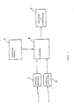
- Optical detectors 1 and 2 measure two spectral radiances from a heated target material (not shown) at different conditions of measurement, for example, at different wavelengths, at different viewing angles, etc. and transfer the measured signals to a computer 4.
- the detectors 1 and 2 are preferably, though not necessarily, designed for each specific application. For example, if galvannealed steel in an alloying furnace is the target material, then the detectors are preferably set for two different wavelengths, e.g., 1.6 and 3.0 (u. m), but are set at the same viewing angle and direction of polarization.
- the detectors include germanium and lead sulfide.
- calibration data based on a blackbody furnace, (essential for any radiation thermometric technique) and apriori data relating two emissivities for the heated target material stored in terms of a mathematical expression, e.g., a polynomial function, or simply as a numerical data table.
- the emissivity data for the target material is generally gathered experimentally or by theoretically analyses prior to use of the present method will be discussed below with reference to several other figures.
- a second spectral radiance L 2 at wavelength X 2 measured at a detector, e.g., detector 2 of Figure 1 can be written as follows:
- Equations (6) and (7), as used herein, are termed "temperature equations.”
- equations (6) and (7) are rewritten as follows: Raising both sides of equation (13) to the ⁇ 2 / ⁇ 1 power and dividing into equation (12), the resultant emissivity relationship will be obtained. Substituting equation (11) into equation (14), the following spectral emissivity relationship at one condition relative to another can be defined as:
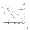
- a curve G prescribed by equation (15) derived from temperature equations (6) and (7), represents possible values of emissivities ⁇ 1 and 62 for various target material temperatures. Then, if an emissivity function, prescribed by a curve F, is defined for the target material from apriori knowledge as then the intersection of curves F and G represents unique emissivity values satisfying both the emissivity function, equation (16) and temperature equations (6) and (7) or (15), the values which define a true temperature of the target material.
- the relationship between two emissivities of the target material is determined apriori through experiments or theoretical analysis.
- the relationship between the spectral emissivities may be specified as a polynomial or other mathematical expression.
- the spectral radiances from the object L 1 and L 2 are measured under specified conditions at viewing angles 0 1 , 0 2 measured from the normal to the surface and at polarization conditions denoted by P, and P 2
- the blackbody radiances L b (X ,T) are determined by conventional means from observations on a reference blackbody.
- at least one measuring condition must be varied for differentiating the two emissivities. Measuring conditions which can be varied include wavelength X, detector viewing angle e, direction of polarization parameters P or any combination of the above.
- the emissivity function is derived from actual measured values of two emissivities of the target material, more accurate temperature measurement is possible than by conventional spectral and ratio pyrometry which assume either constant emissivity or a constant ratio of emissivities.
- the emissivity function can be stored in the computer memory 3 either as a mathematical expression, such as a polynominal function, or as a numerical data table.
- the computer 4 receives the two spectral radiance signals from detectors 1 and 2, then reads the blackbody calibration data and the emissivity function from memory to calculate the true temperature and spectral emissivities by trial and error using equations (6), (7) and (16). The calculated results are fed to a recorder or temperature controller 5.
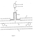
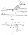
- Figure 2 shows one embodiment of the invention adapted to a continuous annealing furnace used in the steel industry.
- a steel strip 6 is conveyed in a continuous annealing furnace supported by rolls 10.
- Spectral radiances are measured normal to the steel strip at two different wavelengths by a detector 7 through an optical window 8.
- a water-cooled flange 9, whose surface is blackened with black-paint or by oxidation and roughening treatment, is used, if necessary, to reduce stray radiation from furnace wall 11.
- a water cooled flange is not necessary.
- the optical clarity of window 8 may be maintained by use of a purging gas.
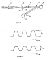
- Figure 3a illustrates one example of an optical system of a detection device for use in the method of the invention.
- Spectral radiation from the target material (not shown) is focused by a lens 12 on an aperture 13, the transmitted flux then being collimated by lens 16 and directed to a detector 18.
- a bandpass filter 17 transmits one narrow spectral portion of radiation to detector 18, and reflects the remaining portion of radiation toward detector 20.
- a second bandpass filter 19 transmits another narrow spectral portion of radiation to detector 20.
- An optical chopper comprising chopping blade 14 and a motor 15, is used to generate AC signals in order to reduce other noise components.
- Figure 3b shows an example of the output signals of detectors 18 and 20 from the optical system of Figure 3a.
- Two signals, L, and L 2 which are proportional to two spectral radiances from the target material, are fed to a computer for temperature calculation as described above.
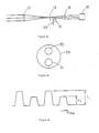
- FIGs 4a and 4b illustrate another example of an optical system for use in the method of the present invention.
- chopping blade 29 of the optical chopper has two bandpass fillers 30, 31 of different wavelengths to generate a signal as shown in Figure 4c.
- only one detector, capable of detecting spectral radiances at two different wavelengths, is necessary for measurement.
- Figure 4c presents an example of detected signals, L 1 and L 2 , which correspond to two spectral radiances from the target material, measured using a synchronous signal from the optical chopper of Figure 4b.
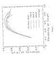
- Figure 5 shows an example of the relationship between two normal spectral emissivities of cold rolled carbon steel as it undergoes oxidation at different temperatures.
- Normal spectral emissivities at 1.6 lm and 3.0 "m were measured using three steel specimens at temperatures of about 700, 800 and 900 K. The steel specimens were oxidized gradually by introducing oxygen in a furnace in which the specimens were heated. Three curves were generated at 700, 800 and 900K which illustrate the variation of spectral emissivities during oxidation.
- spectral emissivities during oxidation show a very complex behavior which also changes due to the temperature.
- an average emissivity relationship between two spectral emissivities designated by solid line in figure 5, provides a good approximation to all three temperature curves.
- the emissivity relationship is thereafter used to generate an emissivity function for calculating the true temperature of the target material according to the method of the invention.
- thermoelectric it is not essential for the method of the invention to generate an emmisivity function for each approximate temperature to be measured.
- temperature is one of the parameters which causes a variation in the emissivity of materials, its influence is often much smaller than the effect of changing surface characteristics, e.g. degree of oxidation, alloying, chemical composition, roughness, etc.
- an emissivity function be generated for each approximate temperature to be measured.
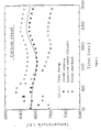
- Figure 6 shows an example of temperature measurement of cold-rolled carbon steel by the method of the invention as it is oxidized.
- the relationship between two spectral emissivities at 1.6 ⁇ m and 3.0 "m is stored in computer memory as a third order polynomial emissivity function.
- the average value of emissivities and the average value of the ratio of two emissivities were also stored in the computer memory.
- a solid line shows the true temperature of the object measured by a thermocouple attached to the object.
- Solid circles represent the temperatures measured by the method of this invention, and open triangle and squares represent temperature measurements obtained by conventional spectral pyrometry using 1.6 a m and ratio pyrometry using 1.6 ⁇ m and 3.0 u. m, respectively.
- the dominant cause of variation in spectral emissivity for cold-rolled steel is oxidation, and as shown in Figure 6, the method of this invention is quite advantageous to such kind of radiation thermometric application. It is also known that the spectral emissivity of galvannealed steel during the alloying process shows a significant change. However, the dominant cause of this variation is not oxidation but the change of iron and zinc composition and a surface roughening effect due to the growth of alloy crystal on the surface. However, the method of this invention is also applicable to galvannealed steel with excellent accuracy.
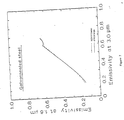
- Figure 7 shows the relationship between two . spectral emissivities at 1.6 u. m and 3.0 a m of galvannealed steel as alloying of iron and zinc proceeds on the surface.
- Four specimens were used for the measurement of the relationship between two emissivities at 720 K through 800 K for different heating rates, and since these specimens showed fairly good coincidence with each other, only one example of actual data is shown as a dotted line in Figure 7.
- a solid line represents the average curve for all four specimens.
- Figure 8 illustrates another example of the improved temperature measurement of galvannealed steel using the method of the present invention.
- Open triangles and squares represent temperatures measured by conventional spectral and ratio color pyrometry using average values of emissivity and emissivity ratios, respectively.
- the method of the invention provides superior accuracy compared to conventional methods during the galvannealing process.
- the spectral emissivity is also a function of viewing angle from the normal to the target material's surface and/or direction of polarization of radiation
- other aspects of this invention employ two radiances measured at either different viewing angles or different directions of polarization.
- Figure 9a illustrates an alternate embodiment of the invention applied to a steel strip 6 in a continuous annealing furnace.
- Spectral radiances are measured at the same wavelength and at an oblique angle from the normal to the target material surface, but at different directions of polarization by detector 22.
- a water cooled flagne 21 is used to reduce stray radiation from the wall, if necessary, while item 8 denotes a transmitting optical window.
- the detector viewing angle a can be adjusted to optimize the system's performance based on data obtained by experiments as well as practical engineering conditions.
- Figure 9b illustrates an optical system for use in the detector 22 of Figure 9a.
- a lens 12 focuses the radiant flux on an optical aperture 13, and the transmitted flux is collimated by another lens 16 and directed to polarizing prism 23.
- a bandpass filer 17 transmits a narrow spectral portion of radiation to the prism 23. Components of two different polarizations of radiation are transmitted or reflected toward detectors 18,20.
- a chopping blade 14 and a motor 15 form an optical chopper.
- Figure 10 illustrates another embodiment of this invention applied to a steel strip 6 in a continuous annealing furnace. Spectral radiances at the same wavelength are measured at different viewing angles e by two detecting devices 27,28 through transmitting windows 24,25. Item 26 denotes a water cooled flange. Item 10 is a supporting roll and item 11 denotes the wall of the furnace. The detector viewing angle 9 can also be adjusted for the optimum operation of the system considering the experimental data as well as practical engineering conditions.
- emissivity function data is generally gathered experimentally for a particular process which employs a specific target material e.g. carbon steel, as shown in Figure 12.
- the emissivity function data is either stored as a table or defined mathematically, for example, in terms of a polynomial equation i.e., equation (16) illustrated graphically in Fig. 13 and as curve F in Fig. 11, and stored in a computer.
- temperature equations (6) and (7) are stored in the computer for calculating emissivities based on observed spectral radiances L 1 and L 2 and an assumed target material temperature. Equation (15), derived from the temperature equations, is represented graphically as curve G in Fig. 11.
- the method according to the present mention is a trial and error method whereby spectral radiances L 1 and L 2 are observed at two different conditions, e.g. two different wavelenths, and a target material temperature T, is assumed and inputed into the computer. Based on this imputed data, emissivities ⁇ 1 and ⁇ 2 are calculated using temperature equations (6) and (7). The calculated emissivities ⁇ 1 and E2 represent a solution to equation (15) and lie on curve G of Figure 11. If the assumed temperature T i is below the true temperature T of the target material the calculated emissivities will lie on curve G at a point above the emissivity function defined by curve F.
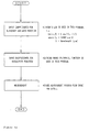
- FIG 14. A block diagram of the main numerical calculation program is illustrated in Figure 14.
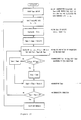
- FIG. 15 A flow chart for the iterative numerical calculation of the target material temperature T and emissivities ⁇ 1 and ⁇ 2 is shown in Figure 15.
- a blackbody function and an emissivity function are defined prior to measurement of the spectral radiances.
- Emissivity function data was gathered experimentally (See, for example, Figure 5) and the coefficients Ao, A 1 , A 2 and A3 were calculated and inputed into the main program.
- T max , T min and T med initial parameters for maximum, minimum and median values of temperature, defined as T max , T min and T med are estimated and inputed into the program.
- T med is the numerical average of T max and Tmin.
- the temperature parameters correspond to emissivities ⁇ 2min , E2max and ⁇ 2med , respectively.
- Identical equations are used for T max and T med to calculate maximum and median emmisivities.
- the emissivity function is then calculated using the polynomial function defined above and deviations, ⁇ , i.e. the difference between the emissivity function f( E2 ) and E , the calculated emissivities ⁇ 1min and ⁇ 1med are determined.
- the deviations ⁇ min and ⁇ med are used to reset T min or T max for the subsequent iteration.
Landscapes
- Physics & Mathematics (AREA)
- General Physics & Mathematics (AREA)
- Spectroscopy & Molecular Physics (AREA)
- Radiation Pyrometers (AREA)
Applications Claiming Priority (2)
| Application Number | Priority Date | Filing Date | Title |
|---|---|---|---|
| US07/175,051 US4881823A (en) | 1988-03-29 | 1988-03-29 | Radiation thermometry |
| US175051 | 1988-03-29 |
Publications (3)
| Publication Number | Publication Date |
|---|---|
| EP0335224A2 true EP0335224A2 (de) | 1989-10-04 |
| EP0335224A3 EP0335224A3 (en) | 1990-10-31 |
| EP0335224B1 EP0335224B1 (de) | 1995-08-09 |
Family
ID=22638647
Family Applications (1)
| Application Number | Title | Priority Date | Filing Date |
|---|---|---|---|
| EP89104999A Expired - Lifetime EP0335224B1 (de) | 1988-03-29 | 1989-03-21 | Verfahren zur Strahlungsthermometrie |
Country Status (4)
| Country | Link |
|---|---|
| US (1) | US4881823A (de) |
| EP (1) | EP0335224B1 (de) |
| JP (1) | JPH0623672B2 (de) |
| DE (1) | DE68923722T2 (de) |
Cited By (7)
| Publication number | Priority date | Publication date | Assignee | Title |
|---|---|---|---|---|
| EP0592361A1 (de) * | 1992-10-06 | 1994-04-13 | Alusuisse-Lonza Services Ag | Temperaturmessung mit Zweiwellenlängenpyrometern |
| US5507576A (en) * | 1993-04-01 | 1996-04-16 | European Gas Turbines Sa | Bichromatic pyrometer |
| WO1997011340A1 (en) * | 1995-09-06 | 1997-03-27 | 3T True Temperature Technologies | Method and apparatus for true temperature determination |
| EP0846939A1 (de) * | 1994-05-30 | 1998-06-10 | Nkk Corporation | Verfahren zur Temperaturmessung mittels einer optischen Faser und Vorrichtung dafür |
| EP2505976A1 (de) * | 2011-03-29 | 2012-10-03 | Univ Paris Ouest Nanterre la Defense | Messung des Wärmeemissionsvermögens eines Körpers |
| CN103900723B (zh) * | 2014-04-25 | 2016-08-24 | 天津送变电易通电力科技有限公司 | 利用辐射谱的全部信息测火焰实际温度的方法及测量系统 |
| EP3351913A4 (de) * | 2015-09-16 | 2019-02-27 | Mitsubishi Materials Corporation | Verfahren zur messung der temperatur eines zu messenden objekts, staubtemperatur und staubkonzentration |
Families Citing this family (46)
| Publication number | Priority date | Publication date | Assignee | Title |
|---|---|---|---|---|
| US5132922A (en) * | 1989-01-12 | 1992-07-21 | Massachusetts Institute Of Technology | Emissivity independent multiwavelength pyrometer |
| US5249142A (en) * | 1989-03-31 | 1993-09-28 | Tokyo Electron Kyushu Limited | Indirect temperature-measurement of films formed on semiconductor wafers |
| US5150969A (en) * | 1990-03-12 | 1992-09-29 | Ivac Corporation | System and method for temperature determination and calibration in a biomedical probe |
| US5165791A (en) * | 1990-09-18 | 1992-11-24 | Sumitomo Electric Industries, Ltd. | Method and apparatus for measuring temperature based on infrared light |
| US5114242A (en) * | 1990-12-07 | 1992-05-19 | Ag Processing Technologies, Inc. | Bichannel radiation detection method |
| US5165796A (en) * | 1990-12-07 | 1992-11-24 | Ag Processing Technologies, Inc. | Bichannel radiation detection apparatus |
| US5086220A (en) * | 1991-02-05 | 1992-02-04 | The Babcock & Wilcox Company | Radiation imaging fiber optic temperature distribution monitor |
| JPH04333529A (ja) * | 1991-05-07 | 1992-11-20 | Nippon Steel Corp | ストリップ連続熱処理設備用冷却装置 |
| US5186541A (en) * | 1991-10-21 | 1993-02-16 | Gentri Controls, Inc. | Non-contact infrared temperature sensing system |
| US5314249A (en) * | 1991-11-19 | 1994-05-24 | Kawasaki Steel Corporation | Surface condition measurement apparatus |
| DE69209270T2 (de) * | 1991-12-13 | 1996-08-08 | Kawasaki Steel Co | Verfahren und Vorrichtung zur Prozesssteuerung eines Strahlung aussendenden Materials |
| US5505543A (en) * | 1994-01-21 | 1996-04-09 | The Boeing Company | Emissivity measurement apparatus and method |
| MY113681A (en) * | 1994-03-22 | 2002-04-30 | Casio Computer Co Ltd | Thermometer |
| US5868496A (en) * | 1994-06-28 | 1999-02-09 | Massachusetts Institute Of Technology | Non-contact surface temperature, emissivity, and area estimation |
| US5755511A (en) * | 1994-12-19 | 1998-05-26 | Applied Materials, Inc. | Method and apparatus for measuring substrate temperatures |
| US6179466B1 (en) * | 1994-12-19 | 2001-01-30 | Applied Materials, Inc. | Method and apparatus for measuring substrate temperatures |
| US5660472A (en) * | 1994-12-19 | 1997-08-26 | Applied Materials, Inc. | Method and apparatus for measuring substrate temperatures |
| FI100135B (fi) * | 1996-01-05 | 1997-09-30 | Vaisala Oy | Menetelmä ja lämpötila-anturirakenne säteilyvirheen eliminoimiseksi |
| US5690430A (en) * | 1996-03-15 | 1997-11-25 | Bethlehem Steel Corporation | Apparatus and method for measuring temperature and/or emissivity of steel strip during a coating process |
| US5864776A (en) * | 1997-08-27 | 1999-01-26 | Mitsubishi Electric America, Inc. | Apparatus and method for detecting an error in the placement of a lead frame on a surface of a die mold |
| JP4187329B2 (ja) * | 1997-11-21 | 2008-11-26 | オメガ エンジニアリング,インコーポレイテッド | 片手持ち型の計器を用いた放射率の表示方法及び放射率の表示手段を備える片手持ち型の計器 |
| US7155363B1 (en) * | 1997-12-01 | 2006-12-26 | Mks Instruments, Inc. | Thermal imaging for semiconductor process monitoring |
| DE19757447A1 (de) * | 1997-12-23 | 1999-07-01 | Braun Gmbh | Temperaturberechnungsverfahren für Strahlungsthermometer |
| US6007241A (en) * | 1998-02-20 | 1999-12-28 | Applied Materials, Inc. | Apparatus and method for measuring substrate temperature |
| US6183130B1 (en) | 1998-02-20 | 2001-02-06 | Applied Materials, Inc. | Apparatus for substrate temperature measurement using a reflecting cavity and detector |
| US6379038B1 (en) * | 1998-06-22 | 2002-04-30 | Ralph A. Felice | Temperature determining device and process |
| US6174080B1 (en) | 1998-08-06 | 2001-01-16 | Applied Materials, Inc. | Apparatus and methods for measuring substrate temperature |
| US6164816A (en) * | 1998-08-14 | 2000-12-26 | Applied Materials, Inc. | Tuning a substrate temperature measurement system |
| AU3726100A (en) * | 1999-03-08 | 2000-09-28 | C.I. Systems Ltd. | Method and apparatus for active pyrometric measurement of the temperature of a body whose emissivity varies with wavelength |
| US6947802B2 (en) * | 2000-04-10 | 2005-09-20 | Hypertherm, Inc. | Centralized control architecture for a laser materials processing system |
| US7186947B2 (en) * | 2003-03-31 | 2007-03-06 | Hypertherm, Inc. | Process monitor for laser and plasma materials processing of materials |
| AU2004271181A1 (en) * | 2003-09-04 | 2005-03-17 | Quartex | Temperature measuring apparatus |
| JP2007218591A (ja) * | 2006-02-14 | 2007-08-30 | Toyo Univ | ハイブリッド型表面温度計、温度分布測定装置及び測定方法 |
| US8251157B2 (en) | 2008-03-07 | 2012-08-28 | Milwaukee Electric Tool Corporation | Battery pack for use with a power tool and a non-motorized sensing tool |
| US20090257469A1 (en) * | 2008-04-09 | 2009-10-15 | Jones Mike N | Infrared thermometer |
| EP2251658B1 (de) * | 2009-05-12 | 2012-01-25 | LayTec Aktiengesellschaft | Verfahren zur Kalibrierung eines Pyrometers, Verfahren zur Bestimmung der Temperatur eines Halbleiterwafers und System zur Bestimmung der Temperatur eines Halbleiterwafers |
| JP6035831B2 (ja) | 2012-04-13 | 2016-11-30 | Jfeスチール株式会社 | 温度測定方法および温度測定装置 |
| CN105319239B (zh) * | 2015-12-03 | 2017-11-28 | 河南师范大学 | 一种材料极化方向发射率测量装置的控制方法 |
| FR3059824B1 (fr) * | 2016-12-07 | 2019-06-21 | Ulis | Capteur d'image infrarouge |
| CN108168709B (zh) * | 2017-12-21 | 2019-10-15 | 合肥工业大学 | 一种托卡马克偏滤器靶板温度精确测量方法 |
| JP7120834B2 (ja) * | 2018-07-11 | 2022-08-17 | 株式会社神戸製鋼所 | 酸化膜厚測定装置および該方法 |
| JP7751508B2 (ja) | 2022-02-25 | 2025-10-08 | 株式会社Screenホールディングス | 温度測定方法および熱処理装置 |
| CN115265825B (zh) * | 2022-07-06 | 2024-04-16 | 东北大学 | 内表面温度测量方法及装置、存储介质、终端 |
| KR20250022859A (ko) | 2022-08-05 | 2025-02-17 | 닛폰세이테츠 가부시키가이샤 | 온도 측정 장치 및 온도 측정 방법 |
| JP7827987B2 (ja) * | 2022-08-05 | 2026-03-11 | 日本製鉄株式会社 | 温度測定装置及び温度測定方法 |
| CN117232661B (zh) * | 2023-11-16 | 2024-02-23 | 中国人民解放军63921部队 | 一种多通道红外辐射测量系统及多波长实时温度测量方法 |
Family Cites Families (22)
| Publication number | Priority date | Publication date | Assignee | Title |
|---|---|---|---|---|
| DE1179733B (de) * | 1960-09-16 | 1964-10-15 | Siemens Ag | Korrekturschaltung fuer Farbpyrometer |
| US3537314A (en) * | 1966-04-09 | 1970-11-03 | Dary Yakovlevich Svet | Method and apparatus for measuring true or actual temperature of bodies by radiant energy |
| US3608817A (en) * | 1968-12-09 | 1971-09-28 | Dary Yakovlevich Svet | Method of controlling color of an object by its radiation and device for accomplishing the same |
| US3611805A (en) * | 1969-07-28 | 1971-10-12 | Chino Works Ltd | Radiation thermometer |
| US3616592A (en) * | 1970-02-09 | 1971-11-02 | Irving Rothman | Method of constructing building units |
| SU386269A1 (ru) * | 1971-04-22 | 1973-06-14 | Спектральный способ определения излучательнои способности нагретых тел | |
| US4020695A (en) * | 1975-09-18 | 1977-05-03 | Jones & Laughlin Steel Corporation | Method and apparatus for measurement of surface temperature |
| GB1599949A (en) * | 1977-04-04 | 1981-10-07 | Nippon Steel Corp | Method and an apparatus for simultaneous measurement of both temperature and emissivity of a heated material |
| JPS6046371B2 (ja) * | 1977-04-04 | 1985-10-15 | 新日本製鐵株式会社 | 金属の表面温度と放射率の同時測定方法および装置 |
| JPS55144513A (en) * | 1979-04-28 | 1980-11-11 | Jeol Ltd | Measuring method of emissivity |
| JPS6038646B2 (ja) * | 1979-06-05 | 1985-09-02 | 昭和電工株式会社 | 放射率測定法 |
| JPS5635026A (en) * | 1979-08-30 | 1981-04-07 | Toshiba Corp | Temperature estimating system for heated object |
| JPS6049849B2 (ja) * | 1980-08-01 | 1985-11-05 | 新日本製鐵株式会社 | 物体の表面温度と放射率の測定装置 |
| JPS57153228A (en) * | 1981-03-18 | 1982-09-21 | Shimadzu Corp | Measuring apparatus for temperature of atomizing furnace of sample for atom absorptiometry |
| DE3115887C2 (de) * | 1981-04-21 | 1986-07-03 | Deutsche Forschungs- und Versuchsanstalt für Luft- und Raumfahrt e.V., 5000 Köln | Verfahren und Vorrichtung zur berührungslosen Infrarot-Strahlungsmessung der Temperatur eines Strahlers |
| FR2508637A1 (fr) * | 1981-06-25 | 1982-12-31 | Paris X Nanterre Universite | Perfectionnements apportes aux procedes de mesures a distance de l'emissivite et/ou de la temperature vraie d'un corps a surface relativment lisse |
| JPS58169038A (ja) * | 1982-03-31 | 1983-10-05 | Nippon Light Metal Co Ltd | 二色形放射温度計 |
| US4579461A (en) * | 1983-02-14 | 1986-04-01 | United States Steel Corporation | Dual sensor radiation pyrometer |
| JPS60152924A (ja) * | 1984-01-23 | 1985-08-12 | Ulvac Corp | 放射温度測定方法 |
| JPS60165524A (ja) * | 1984-02-08 | 1985-08-28 | Ulvac Corp | 放射率測定方法 |
| US4561786A (en) * | 1984-03-15 | 1985-12-31 | Williamson Corporation | Temperature measuring apparatus |
| US4708493A (en) * | 1986-05-19 | 1987-11-24 | Quantum Logic Corporation | Apparatus for remote measurement of temperatures |
-
1988
- 1988-03-29 US US07/175,051 patent/US4881823A/en not_active Expired - Lifetime
- 1988-10-28 JP JP63271047A patent/JPH0623672B2/ja not_active Expired - Lifetime
-
1989
- 1989-03-21 EP EP89104999A patent/EP0335224B1/de not_active Expired - Lifetime
- 1989-03-21 DE DE68923722T patent/DE68923722T2/de not_active Expired - Lifetime
Cited By (10)
| Publication number | Priority date | Publication date | Assignee | Title |
|---|---|---|---|---|
| EP0592361A1 (de) * | 1992-10-06 | 1994-04-13 | Alusuisse-Lonza Services Ag | Temperaturmessung mit Zweiwellenlängenpyrometern |
| US5507576A (en) * | 1993-04-01 | 1996-04-16 | European Gas Turbines Sa | Bichromatic pyrometer |
| EP0846939A1 (de) * | 1994-05-30 | 1998-06-10 | Nkk Corporation | Verfahren zur Temperaturmessung mittels einer optischen Faser und Vorrichtung dafür |
| WO1997011340A1 (en) * | 1995-09-06 | 1997-03-27 | 3T True Temperature Technologies | Method and apparatus for true temperature determination |
| US6016190A (en) * | 1995-09-06 | 2000-01-18 | 3T True Temperature Technologies | Method and apparatus for true temperature determination |
| EP2505976A1 (de) * | 2011-03-29 | 2012-10-03 | Univ Paris Ouest Nanterre la Defense | Messung des Wärmeemissionsvermögens eines Körpers |
| FR2973507A1 (fr) * | 2011-03-29 | 2012-10-05 | Univ Paris Ouest Nanterre La Defense | Mesure de l'emissitivite thermique d'un corps |
| CN103900723B (zh) * | 2014-04-25 | 2016-08-24 | 天津送变电易通电力科技有限公司 | 利用辐射谱的全部信息测火焰实际温度的方法及测量系统 |
| US11359967B2 (en) | 2014-04-25 | 2022-06-14 | Tianjin Yitong Transmission & Distribution Electric Technology Co. Ltd. | Method for measuring actual temperature of flame by using all information of radiation spectrum and measurement system thereof |
| EP3351913A4 (de) * | 2015-09-16 | 2019-02-27 | Mitsubishi Materials Corporation | Verfahren zur messung der temperatur eines zu messenden objekts, staubtemperatur und staubkonzentration |
Also Published As
| Publication number | Publication date |
|---|---|
| JPH0623672B2 (ja) | 1994-03-30 |
| DE68923722D1 (de) | 1995-09-14 |
| EP0335224A3 (en) | 1990-10-31 |
| DE68923722T2 (de) | 1996-04-18 |
| JPH0285730A (ja) | 1990-03-27 |
| US4881823A (en) | 1989-11-21 |
| EP0335224B1 (de) | 1995-08-09 |
Similar Documents
| Publication | Publication Date | Title |
|---|---|---|
| US4881823A (en) | Radiation thermometry | |
| US4172383A (en) | Method and an apparatus for simultaneous measurement of both temperature and emissivity of a heated material | |
| US5690429A (en) | Method and apparatus for emissivity independent self-calibrating of a multiwavelength pyrometer | |
| GB2101309A (en) | Improvements to processes for the remote measurement of the emissivity and/or the true temperature of a body with relatively smooth surface | |
| Tanaka et al. | Theory of a new radiation thermometry method and an experimental study using galvannealed steel specimens | |
| DeWitt et al. | Measurement of surface temperatures and spectral emissivities duringlaser irradiation | |
| JPS6049246B2 (ja) | 赤外線による温度測定方法における測定値補償方法 | |
| JP2002303551A (ja) | 炉内金属材の温度測定方法および装置 | |
| Richmond et al. | 41-AN APPROACH TO THERMAL EMITTANCE STANDARDS | |
| JPH05273043A (ja) | 放射温度測定装置、放射率測定装置及び放射率累乗比−放射率相関決定の方法 | |
| JP2632086B2 (ja) | 放射測温法及び該測温法に用いる放射温度計 | |
| JPH05231944A (ja) | 多波長を用いた放射測温方法 | |
| JPH06147989A (ja) | 比較的低温物体の表面温度測定方法及び装置 | |
| De Witt | Advances and Challenges in Radiation Thermometry | |
| JPH08219891A (ja) | 鋼板の表面性状測定方法及び鋼板温度測定方法 | |
| JPH0933353A (ja) | 放射測温方法およびその測温装置 | |
| RU1770779C (ru) | Способ бесконтактного определени температуры | |
| JPH05215610A (ja) | 表面状態測定装置 | |
| JPH04276527A (ja) | 炉内温度計 | |
| JP3424373B2 (ja) | 赤外線放射温度計測方法 | |
| JPH0579920A (ja) | 二色放射測温法および二色放射温度計 | |
| JPH06265410A (ja) | 輻射を用いたプロセス状態検出装置及び制御装置 | |
| Tanaka et al. | Application of a new radiation thermometry method to galvannealed and cold-rolled steels | |
| JPH0815036A (ja) | 新しい内挿公式を利用して輻射温度計及び光計測装備を矯正する方法 | |
| JPH0310128A (ja) | 高温炉内における温度と放射率の同時測定方法 |
Legal Events
| Date | Code | Title | Description |
|---|---|---|---|
| PUAI | Public reference made under article 153(3) epc to a published international application that has entered the european phase |
Free format text: ORIGINAL CODE: 0009012 |
|
| AK | Designated contracting states |
Kind code of ref document: A2 Designated state(s): DE FR GB IT |
|
| PUAL | Search report despatched |
Free format text: ORIGINAL CODE: 0009013 |
|
| AK | Designated contracting states |
Kind code of ref document: A3 Designated state(s): DE FR GB IT |
|
| 17P | Request for examination filed |
Effective date: 19910417 |
|
| 17Q | First examination report despatched |
Effective date: 19920519 |
|
| GRAA | (expected) grant |
Free format text: ORIGINAL CODE: 0009210 |
|
| AK | Designated contracting states |
Kind code of ref document: B1 Designated state(s): DE FR GB IT |
|
| ITF | It: translation for a ep patent filed | ||
| REF | Corresponds to: |
Ref document number: 68923722 Country of ref document: DE Date of ref document: 19950914 |
|
| ET | Fr: translation filed | ||
| PLBE | No opposition filed within time limit |
Free format text: ORIGINAL CODE: 0009261 |
|
| STAA | Information on the status of an ep patent application or granted ep patent |
Free format text: STATUS: NO OPPOSITION FILED WITHIN TIME LIMIT |
|
| 26N | No opposition filed | ||
| REG | Reference to a national code |
Ref country code: GB Ref legal event code: IF02 |
|
| PGFP | Annual fee paid to national office [announced via postgrant information from national office to epo] |
Ref country code: IT Payment date: 20080327 Year of fee payment: 20 Ref country code: GB Payment date: 20080326 Year of fee payment: 20 |
|
| PGFP | Annual fee paid to national office [announced via postgrant information from national office to epo] |
Ref country code: DE Payment date: 20080313 Year of fee payment: 20 Ref country code: FR Payment date: 20080311 Year of fee payment: 20 |
|
| REG | Reference to a national code |
Ref country code: GB Ref legal event code: PE20 Expiry date: 20090320 |
|
| PG25 | Lapsed in a contracting state [announced via postgrant information from national office to epo] |
Ref country code: GB Free format text: LAPSE BECAUSE OF EXPIRATION OF PROTECTION Effective date: 20090320 |