EP0336862A1 - Procédé de réalisation d'un chanfrein extérieur sur une pièce cylindrique emboutie - Google Patents
Procédé de réalisation d'un chanfrein extérieur sur une pièce cylindrique emboutie Download PDFInfo
- Publication number
- EP0336862A1 EP0336862A1 EP89420120A EP89420120A EP0336862A1 EP 0336862 A1 EP0336862 A1 EP 0336862A1 EP 89420120 A EP89420120 A EP 89420120A EP 89420120 A EP89420120 A EP 89420120A EP 0336862 A1 EP0336862 A1 EP 0336862A1
- Authority
- EP
- European Patent Office
- Prior art keywords
- punch
- cup
- stamping
- die
- carried out
- Prior art date
- Legal status (The legal status is an assumption and is not a legal conclusion. Google has not performed a legal analysis and makes no representation as to the accuracy of the status listed.)
- Granted
Links
- 238000004519 manufacturing process Methods 0.000 title claims abstract description 7
- 238000000034 method Methods 0.000 claims description 8
- 239000011159 matrix material Substances 0.000 claims description 3
- 230000002093 peripheral effect Effects 0.000 claims description 2
- 230000000694 effects Effects 0.000 claims 1
- 101100327917 Caenorhabditis elegans chup-1 gene Proteins 0.000 description 4
- 238000005520 cutting process Methods 0.000 description 3
- 238000000605 extraction Methods 0.000 description 2
- 239000002184 metal Substances 0.000 description 2
- 238000004140 cleaning Methods 0.000 description 1
- 230000000295 complement effect Effects 0.000 description 1
- 235000014510 cooky Nutrition 0.000 description 1
- 238000005553 drilling Methods 0.000 description 1
- 239000000463 material Substances 0.000 description 1
- 238000003860 storage Methods 0.000 description 1
Images

Classifications
-
- B—PERFORMING OPERATIONS; TRANSPORTING
- B21—MECHANICAL METAL-WORKING WITHOUT ESSENTIALLY REMOVING MATERIAL; PUNCHING METAL
- B21D—WORKING OR PROCESSING OF SHEET METAL OR METAL TUBES, RODS OR PROFILES WITHOUT ESSENTIALLY REMOVING MATERIAL; PUNCHING METAL
- B21D35/00—Combined processes according to or processes combined with methods covered by groups B21D1/00 - B21D31/00
-
- B—PERFORMING OPERATIONS; TRANSPORTING
- B21—MECHANICAL METAL-WORKING WITHOUT ESSENTIALLY REMOVING MATERIAL; PUNCHING METAL
- B21D—WORKING OR PROCESSING OF SHEET METAL OR METAL TUBES, RODS OR PROFILES WITHOUT ESSENTIALLY REMOVING MATERIAL; PUNCHING METAL
- B21D22/00—Shaping without cutting, by stamping, spinning, or deep-drawing
- B21D22/20—Deep-drawing
- B21D22/26—Deep-drawing for making peculiarly, e.g. irregularly, shaped articles
Definitions
- the present invention relates to a method for producing an external chamfer on a stamped cylindrical part.
- Such an external chamfer is conventionally produced by a resumption in turning of the straight edge of the stamped part, this resumption being carried out by means of a tool which removes chips in sufficient quantity to produce the chamfer.
- the invention aims to remedy this drawback.
- a method for producing an external chamfer on a stamped cylindrical part consisting, starting from a flat metallic part: - First of all to carry out a conical pre-stamping of the part to be obtained, using a punch whose end piece has a shape of a truncated cone with an angle substantially equal to that of the chamfer to be obtained, with provision for a peripheral rim plan, - then axially severing the outer periphery of the frustoconical end piece obtained, for example by vertical guillotine shears, - And then straighten, by a final stamping, the frustoconical side wall of this stamped in order to obtain a cup with coaxial wall, the edge of this cup then being provided with an external chamfer.
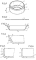
- the part to be obtained 1 is a cup whose bottom 5 is pierced with an orifice 2 for the passage of a drive shaft, and whose edge is provided with an external chamfer 3 This chamfer 3 is practically essential for carrying out the introduction of the cup 1 into an associated bore.
- FIGS 2 to 6 show the essential successive stages in the manufacture of the cup 1.
- the first operation is performed on a first station. It consists of cutting, in a very conventional manner between punch and die, a metal disc 4 of diameter much larger than that of the cup 3.
- This disc 4 is then transferred to another station, where a conical pre-stamping of this disc 4 is carried out, FIG. 3, the angle at the apex ⁇ of the pre-stamping cone being equal to that of the chamfer to be obtained, while is provided , at the periphery of this stamped, a flat edge.
- the tool is shaped so that the small base 5 of the truncated cone 6 obtained has the same diameter as the bottom of the cup to be obtained, and that its flank or apothem 7 has a constant length L substantially equal to the height H (FIG. 1) of this cup.
- the part 6 is then transferred to another station, comprising a guillotine shears with circular periphery which axially cuts, in the vertical direction 8, the external periphery of the frustoconical stamp 6.
- the stamp 6 is then transferred to a fourth station, where its side 7 is straightened axially, that is to say vertically: this side 7 then becomes circular cylindrical and perpendicular to the bottom 5 of the stamp.
- This side 7 is then provided with an external chamfer 3 of angle ⁇ , which is the result that we aim to obtain.
- the piece 6 obtained is then optionally passed through a calibration station, then is made, on a last station ( Figure 6), the central hole 2 for passage of the drive shaft of the cup.
- the tools used for cutting the disc 4 ( Figure 2) and for drilling the hole 2 ( Figure 6) are conventional tools operating as a cookie cutter. They are therefore not represented.
- FIG. 7 shows the tool used for stamping, according to FIG. 3, the frustoconical part 6 from the disc 4.
- This tool comprises a complementary punch 10 and a matrix 11, of frustoconical shape.
- a conventional sidewall press 12 comes to press strongly on the periphery of the disc 4 in order to maintain it during stamping, which prevents the material from wrinkling.
- an extraction pusher 24, pushed upwards by an axial spring 13, equips the die 11.
- FIG. 8 The tool allowing the axial sectioning, according to FIG. 4, of the periphery of the stamping 6, is represented in FIG. 8. It is a circular cutting tool comprising a circular cylindrical punch 14, an associated die 15, a press -wall 16, and an extraction pusher 17 pushed back by a spring 18.
- the tool used for the straightening according to FIG. 5 is represented in FIG. 9. It comprises a beveled flank press 19, a circular cylindrical matrix, of diameter D equal to the external diameter of the cup 1 to be obtained, a pusher 21 with spring. 22, and a circular cylindrical punch 23, of diameter d equal to the inside diameter of the aforementioned cup 1.
Landscapes
- Engineering & Computer Science (AREA)
- Mechanical Engineering (AREA)
- Forging (AREA)
- Shaping Metal By Deep-Drawing, Or The Like (AREA)
- Superconductors And Manufacturing Methods Therefor (AREA)
- Photoreceptors In Electrophotography (AREA)
- Metal Extraction Processes (AREA)
- Containers And Plastic Fillers For Packaging (AREA)
- Processing Of Meat And Fish (AREA)
- Adornments (AREA)
- Polishing Bodies And Polishing Tools (AREA)
Abstract
Description
- La présente invention se rapporte à un procédé de réalisation d'un chanfrein extérieur sur une pièce cylindrique emboutie.
- Pour faciliter l'introduction d'une pièce cylindrique emboutie dans un alésage, il est nécessaire que cette pièce cylindrique ait un chanfrein sur tout son pourtour extérieur, sans quoi, l'introduction de la pièce dans son alésage associé peut être rendue impossible en raison d'irrégularités, aussi minimes soient-elles.
- Un tel chanfrein extérieur est classiquement réalisé par une reprise en tournage de la tranche droite de la pièce emboutie, cette reprise étant effectuée au moyen d'un outil qui enlève des copeaux en quantité suffisante pour réaliser le chanfrein.
- Cette solution traditionnelle est d'un prix de revient élevé. Il faut en effet insérer, dans la chaîne de fabrication, un poste de stockage des pièces embouties mais non encore chanfreinées, puis veiller à transférer ces pièces sur le tour pour y réaliser une opération d'enlèvement de métal. Il faut ensuite prévoir une opération particulière de nettoyage de ces mêmes pièces, de sorte que cette série d'interventions spéciales pénalise lourdement le prix de revient de chaque pièce.
- L'invention vise à remédier à cet inconvénient. Elle se rapporte à cet effet à un procédé de réalisation d'un chanfrein extérieur sur une pièce cylindrique emboutie, ce procédé consistant, en partant d'une pièce métallique plane :
- à réaliser tout d'abord un préemboutissage conique de la pièce à obtenir, en utilisant un poinçon dont l'embout a une forme de tronc de cône d'angle substantiellement égal à celui du chanfrein à obtenir, avec ménagement d'un rebord périphérique plan,
- à sectionner ensuite axialement le pourtour extérieur de l'embout tronconique obtenu, par effet de cisaille-guillotine à coupe verticale par exemple,
- et à redresser ensuite, par un emboutissage final, la paroi latérale tronconique de cet embouti afin d'obtenir une coupelle à paroi coaxiale, le bord de cette coupelle étant alors muni d'un chanfrein extérieur. - L'invention sera bien comprise, et ses avantages et autres caractéristiques ressortiront, au cours de la description suivante d'un exemple non limitatif de réalisation, en référence au dessin schématique annexé dans lequel :
- Figure 1 est une vue en perspective de la pièce à obtenir ;
- Figures 2 à 6 montrent les phases successives d'obtention de cette pièce par le procédé de l'invention ;
- Figures 7 à 9 montrent les trois outils utilisés pour la mise en oeuvre de ce procédé, dans les trois phases successives essentielles d'exécution de ce procédé.
- En se référant à la figure 1, la pièce à obtenir 1 est une coupelle dont le fond 5 est percé d'un orifice 2 pour le passage d'un arbre d'entraînement, et dont le bord est muni d'un chanfrein extérieur 3. Ce chanfrein 3 est pratiquement indispensable pour réaliser l'introduction de la coupelle 1 dans un alésage associé.
- Les figures 2 à 6 montrent les phases successives essentielles de fabrication de la coupelle 1.
- La première opération, figure 2, est effectuée sur un premier poste. Elle consiste à découper, de manière très classique entre poinçon et matrice, un disque métallique 4 de diamètre nettement supérieur à celui de la coupelle 3.
- Ce disque 4 est ensuite transféré vers un autre poste, où est réalisé, figure 3, un préemboutissage conique de ce disque 4, l'angle au sommet α du cône de préemboutissage étant égal à celui du chanfrein à obtenir, tandis qu'est ménagé, à la périphérie de ce préembouti, un rebord plan. L'outil est conformé pour que la petite base 5 du tronc de cône 6 obtenu ait le même diamètre que le fond de la coupelle à obtenir, et que son flanc ou apothème 7 ait une longueur constante L sensiblement égale à la hauteur H (figure 1) de cette coupelle.
- La pièce 6 est alors transférée sur un autre poste, comportant une cisaille-guillotine à pourtour circulaire qui sectionne axialement, selon la direction verticale 8, le pourtour extérieur de l'embouti tronconique 6.
- Le résultat obtenu est représenté en vue partiellement agrandie sur la figure 4 : le bord extérieur 9 de l'embouti 6 forme un angle égal à la valeur α précitée avec son flanc ou apothème 7.
- L'embouti 6 est alors transféré sur un quatrième poste, où son flanc 7 est redressé axialement, c'est-à-dire à la verticale : ce flanc 7 devient alors cylindrique circulaire et perpendiculaire au fond 5 de l'embouti.
- Ce flanc 7 se trouve alors muni d'un chanfrein extérieur 3 d'angle α, ce qui est le résultat que l'on vise à obtenir.
- La pièce 6 obtenue est ensuite facultativement passée par un poste de calibrage, puis est réalisé, sur un dernier poste (figure 6), le trou central 2 de passage de l'arbre d'entraînement de la coupelle.
- Les outils utilisés pour la découpe du disque 4 (figure 2) et pour le perçage du trou 2 (figure 6) sont des outils classiques fonctionnant en emporte-pièce. Ils ne sont en conséquence pas représentés.
- La figure 7 montre l'outil utilisé pour l'emboutissage, selon figure 3, de la pièce tronconique 6 à partir du disque 4. Cet outil comporte un poinçon 10 et une matrice 11 complémentaires, de forme tronconique. Un presse-flanc classique 12 vient appuyer fortement sur le pourtour du disque 4 afin de le maintenir pendant l'emboutissage, ce qui évite à la matière de plisser. De manière classique également, un poussoir d'extraction 24, repoussé vers le haut par un ressort axial 13, équipe la matrice 11.
- L'outil permettant le sectionnement axial, selon figure 4, du pourtour de l'embouti 6, est représenté figure 8. Il s'agit d'un outil de découpe circulaire comportant un poinçon cylindrique circulaire 14, une matrice associée 15, un presse-flanc 16, et un poussoir d'extraction 17 repoussé par un ressort 18.
- L'outil utilisé pour le redressement selon figure 5 est représenté à la figure 9. Il comporte un presse-flanc biseauté 19, une matrice cylindrique circulaire, de diamètre D égal au diamètre extérieur de la coupelle 1 à obtenir, un poussoir 21 avec ressort 22, et un poinçon 23 cylindrique circulaire, de diamètre d égal au diamètre intérieur de la coupelle 1 précitée.
Claims (4)
- à réaliser tout d'abord un préemboutissage conique (6) de la pièce à obtenir, par utilisation d'un poinçon (10) dont l'embout a une forme de tronc de cône d'angle (α) substantiellement égal à celui du chanfrein (3) à obtenir, avec ménagement d'un rebord périphérique plan,
- à sectionner ensuite axialement le pourtour de l'embouti tronconique (6) obtenu et
- à redresser, par un emboutissage final, la paroi latérale tronconique (7) de cet embouti (6) afin d'obtenir une coupelle (1) à paroi coaxiale dont le bord se trouve alors muni d'un chanfrein extérieur (3).
Priority Applications (1)
| Application Number | Priority Date | Filing Date | Title |
|---|---|---|---|
| AT89420120T ATE81804T1 (de) | 1988-04-06 | 1989-03-31 | Verfahren zur herstellung einer aeusseren schraegkante an einem zylindrischen ziehteil. |
Applications Claiming Priority (2)
| Application Number | Priority Date | Filing Date | Title |
|---|---|---|---|
| FR8804971A FR2629742B1 (fr) | 1988-04-06 | 1988-04-06 | Procede de realisation d'un chanfrein exterieur sur une piece cylindrique emboutie |
| FR8804971 | 1988-04-06 |
Publications (2)
| Publication Number | Publication Date |
|---|---|
| EP0336862A1 true EP0336862A1 (fr) | 1989-10-11 |
| EP0336862B1 EP0336862B1 (fr) | 1992-10-28 |
Family
ID=9365324
Family Applications (1)
| Application Number | Title | Priority Date | Filing Date |
|---|---|---|---|
| EP89420120A Expired - Lifetime EP0336862B1 (fr) | 1988-04-06 | 1989-03-31 | Procédé de réalisation d'un chanfrein extérieur sur une pièce cylindrique emboutie |
Country Status (8)
| Country | Link |
|---|---|
| US (1) | US4910989A (fr) |
| EP (1) | EP0336862B1 (fr) |
| AT (1) | ATE81804T1 (fr) |
| CA (1) | CA1289418C (fr) |
| DE (1) | DE68903291T2 (fr) |
| ES (1) | ES2035619T3 (fr) |
| FR (1) | FR2629742B1 (fr) |
| GR (1) | GR3006221T3 (fr) |
Cited By (5)
| Publication number | Priority date | Publication date | Assignee | Title |
|---|---|---|---|---|
| DE4109447A1 (de) * | 1990-07-19 | 1992-01-23 | Degussa | Oberflaechenmodifizierte siliciumdioxide |
| EP0791414A1 (fr) * | 1996-02-26 | 1997-08-27 | Karl Marbach GmbH + Co. | Outil de découpage et d'empartissage |
| US5755132A (en) * | 1996-02-26 | 1998-05-26 | Karl Marbach Gmbh & Co. | Punching and forming tool |
| CN111822942A (zh) * | 2019-04-22 | 2020-10-27 | 安克创新科技股份有限公司 | 装饰网的加工方法 |
| CN112808858A (zh) * | 2021-01-25 | 2021-05-18 | 重庆理工大学 | 用于制作弹簧抱挎的级进模 |
Families Citing this family (7)
| Publication number | Priority date | Publication date | Assignee | Title |
|---|---|---|---|---|
| BRPI0617293A2 (pt) * | 2005-10-11 | 2011-07-19 | Leonard Reiffel | recipientes e método e aparelho para formar recipientes |
| CN101628409B (zh) * | 2008-07-15 | 2011-06-22 | 施俊兆 | 金属工具盒的成型方法 |
| CN102139436B (zh) * | 2010-01-29 | 2013-08-14 | 江苏白雪电器股份有限公司 | 一种金属防护罩的加工方法 |
| CN102615184A (zh) * | 2012-04-04 | 2012-08-01 | 无锡欧易博阀业科技有限公司 | 盘状工件拉伸模具 |
| CN102974976A (zh) * | 2012-11-15 | 2013-03-20 | 重庆黄龙机械制造有限公司 | 金属周转箱的制作方法 |
| WO2014134767A1 (fr) * | 2013-03-04 | 2014-09-12 | Ding Yuwu | Procédé de production et de fabrication de rayon annulaire en acier pour voiture et moule spécifique associé |
| CN104384844A (zh) * | 2014-10-08 | 2015-03-04 | 柳州科尔特锻造机械有限公司 | 一种工程机械钢圈轮辐生产工艺 |
Citations (5)
| Publication number | Priority date | Publication date | Assignee | Title |
|---|---|---|---|---|
| US2321085A (en) * | 1941-11-06 | 1943-06-08 | Electromaster Inc | Method for producing drawn cups with faced and beveled edges |
| US2611475A (en) * | 1948-10-07 | 1952-09-23 | Remington Arms Co Inc | Cup drawing apparatus |
| US3406554A (en) * | 1965-07-06 | 1968-10-22 | Continental Can Co | Apparatus for and method of forming containers |
| DE1932139A1 (de) * | 1969-06-25 | 1971-01-21 | Dynamit Nobel Ag | Verfahren zur Herstellung tiefgezogener Hohlkoerper |
| US4534201A (en) * | 1982-12-29 | 1985-08-13 | American Can Company | Undercut punch to control ironing |
Family Cites Families (5)
| Publication number | Priority date | Publication date | Assignee | Title |
|---|---|---|---|---|
| US161634A (en) * | 1875-04-06 | Improvement in methods of producing flanged lids and collars for sheet-metal cans | ||
| US448748A (en) * | 1891-03-24 | Method of and machine for making cup-shaped articles | ||
| US2415940A (en) * | 1944-10-05 | 1947-02-18 | Remington Arms Co Inc | Metal cupping process |
| SU590053A1 (ru) * | 1976-05-10 | 1978-01-30 | Ижевский механический институт | Способ получени кольцевых деталей |
| SU1016008A1 (ru) * | 1980-07-14 | 1983-05-07 | Предприятие П/Я М-5344 | Способ получени полых изделий с выступом на дне |
-
1988
- 1988-04-06 FR FR8804971A patent/FR2629742B1/fr not_active Expired - Fee Related
-
1989
- 1989-03-30 CA CA000595247A patent/CA1289418C/fr not_active Expired - Lifetime
- 1989-03-31 DE DE8989420120T patent/DE68903291T2/de not_active Expired - Fee Related
- 1989-03-31 AT AT89420120T patent/ATE81804T1/de not_active IP Right Cessation
- 1989-03-31 ES ES198989420120T patent/ES2035619T3/es not_active Expired - Lifetime
- 1989-03-31 EP EP89420120A patent/EP0336862B1/fr not_active Expired - Lifetime
- 1989-04-03 US US07/332,564 patent/US4910989A/en not_active Expired - Fee Related
-
1992
- 1992-11-12 GR GR920402557T patent/GR3006221T3/el unknown
Patent Citations (5)
| Publication number | Priority date | Publication date | Assignee | Title |
|---|---|---|---|---|
| US2321085A (en) * | 1941-11-06 | 1943-06-08 | Electromaster Inc | Method for producing drawn cups with faced and beveled edges |
| US2611475A (en) * | 1948-10-07 | 1952-09-23 | Remington Arms Co Inc | Cup drawing apparatus |
| US3406554A (en) * | 1965-07-06 | 1968-10-22 | Continental Can Co | Apparatus for and method of forming containers |
| DE1932139A1 (de) * | 1969-06-25 | 1971-01-21 | Dynamit Nobel Ag | Verfahren zur Herstellung tiefgezogener Hohlkoerper |
| US4534201A (en) * | 1982-12-29 | 1985-08-13 | American Can Company | Undercut punch to control ironing |
Cited By (7)
| Publication number | Priority date | Publication date | Assignee | Title |
|---|---|---|---|---|
| DE4109447A1 (de) * | 1990-07-19 | 1992-01-23 | Degussa | Oberflaechenmodifizierte siliciumdioxide |
| EP0791414A1 (fr) * | 1996-02-26 | 1997-08-27 | Karl Marbach GmbH + Co. | Outil de découpage et d'empartissage |
| US5755132A (en) * | 1996-02-26 | 1998-05-26 | Karl Marbach Gmbh & Co. | Punching and forming tool |
| CN111822942A (zh) * | 2019-04-22 | 2020-10-27 | 安克创新科技股份有限公司 | 装饰网的加工方法 |
| CN111822942B (zh) * | 2019-04-22 | 2022-04-29 | 安克创新科技股份有限公司 | 装饰网的加工方法 |
| CN112808858A (zh) * | 2021-01-25 | 2021-05-18 | 重庆理工大学 | 用于制作弹簧抱挎的级进模 |
| CN112808858B (zh) * | 2021-01-25 | 2022-11-15 | 重庆理工大学 | 用于制作弹簧抱挎的级进模 |
Also Published As
| Publication number | Publication date |
|---|---|
| US4910989A (en) | 1990-03-27 |
| DE68903291T2 (de) | 1993-06-17 |
| ES2035619T3 (es) | 1993-04-16 |
| CA1289418C (fr) | 1991-09-24 |
| ATE81804T1 (de) | 1992-11-15 |
| EP0336862B1 (fr) | 1992-10-28 |
| DE68903291D1 (de) | 1992-12-03 |
| GR3006221T3 (fr) | 1993-06-21 |
| FR2629742A1 (fr) | 1989-10-13 |
| FR2629742B1 (fr) | 1994-01-14 |
Similar Documents
| Publication | Publication Date | Title |
|---|---|---|
| EP0336862B1 (fr) | Procédé de réalisation d'un chanfrein extérieur sur une pièce cylindrique emboutie | |
| BE1003541A3 (fr) | Procede et appareil pour former des panneaux d'extremites de recipients. | |
| FR2563756A1 (fr) | Procede et appareil pour former un panneau de bout de recipient | |
| EP0363285B1 (fr) | Capsule de surbouchage en aluminium à découpage facile et son procédé de fabrication | |
| FR2542224A1 (fr) | Matrice de retenue d'ebauche | |
| EP0117213A1 (fr) | Outillage de formage à froid de pièces métalliques comportant des éléments axiaux opposés | |
| EP0310726B1 (fr) | Procédé de fabrication de boîtes métalliques tronconiques et outillage pour la mise en oeuvre de ce procédé | |
| CA2031859C (fr) | Procede et dispositif d'emboutissage de recipients de forme tronconique, et recipient ainsi embouti | |
| FR2515885A1 (fr) | Procede de production d'une electrode composite pour bougie d'allumage et cette electrode | |
| FR2549401A1 (fr) | Procede et dispositif de fabrication de cages a poches pour roulements | |
| EP0243257B1 (fr) | Procédé de fabrication d'embases pour tubes à vide ne nécessitant pas de coupe des conducteurs intérieurs après moulage, et dispositif de mise en oeuvre | |
| CH500024A (fr) | Procédé de fabrication de produits métalliques par emboutissage | |
| FR2631262A1 (fr) | Procede pour la production de profiles metalliques creux, et dispositif pour l'execution du procede | |
| TW202606827A (zh) | 利用沖床沖壓特殊工件之成型方法 | |
| FR2695338A1 (fr) | Procédé pour la réalisation de rangées de piqûres sur une surface d'outil destiné à présenter une fonction de râpe, et outils réalisés. | |
| EP0034977A1 (fr) | Procédé industriel de fabrication de bijoux, notamment de bagues, de préférence en métal précieux, comportant des pierres serties, dispositif permettant de mettre en oeuvre ledit procédé de bijoux obtenus | |
| EP0337882A1 (fr) | Procédé et dispositif pour la réalisation de légumes ou fruits tournés et légumes ou fruits tournés obtenus par ce procédé | |
| BE528289A (fr) | ||
| CH380431A (fr) | Dispositif pour évider et couper des fruits avec élimination du trognon | |
| BE464669A (fr) | ||
| BE517037A (fr) | ||
| FR2709111A1 (fr) | Barquette métallique notamment en acier à deux compartiments et procédé de fabrication de ce type de barquettes. | |
| CH103565A (fr) | Procédé et machine pour la fabrication d'une ébauche de tube compressible et ébauche obtenue par ledit procédé. | |
| BE508433A (fr) | ||
| FR2638393A1 (fr) | Procede et dispositif pour fabriquer une boite de carton a fenetre transparente, et boite d'emballage ainsi fabriquee |
Legal Events
| Date | Code | Title | Description |
|---|---|---|---|
| PUAI | Public reference made under article 153(3) epc to a published international application that has entered the european phase |
Free format text: ORIGINAL CODE: 0009012 |
|
| AK | Designated contracting states |
Kind code of ref document: A1 Designated state(s): AT BE CH DE ES FR GB GR IT LI LU NL SE |
|
| 17P | Request for examination filed |
Effective date: 19900120 |
|
| RAP1 | Party data changed (applicant data changed or rights of an application transferred) |
Owner name: A2C GROUPE PRATIC-ADEMVA |
|
| 17Q | First examination report despatched |
Effective date: 19920318 |
|
| RTI1 | Title (correction) | ||
| GRAA | (expected) grant |
Free format text: ORIGINAL CODE: 0009210 |
|
| ITF | It: translation for a ep patent filed | ||
| AK | Designated contracting states |
Kind code of ref document: B1 Designated state(s): AT BE CH DE ES FR GB GR IT LI LU NL SE |
|
| PG25 | Lapsed in a contracting state [announced via postgrant information from national office to epo] |
Ref country code: GR Free format text: LAPSE BECAUSE OF FAILURE TO SUBMIT A TRANSLATION OF THE DESCRIPTION OR TO PAY THE FEE WITHIN THE PRESCRIBED TIME-LIMIT Effective date: 19921028 |
|
| REF | Corresponds to: |
Ref document number: 81804 Country of ref document: AT Date of ref document: 19921115 Kind code of ref document: T |
|
| REF | Corresponds to: |
Ref document number: 68903291 Country of ref document: DE Date of ref document: 19921203 |
|
| GBT | Gb: translation of ep patent filed (gb section 77(6)(a)/1977) | ||
| PG25 | Lapsed in a contracting state [announced via postgrant information from national office to epo] |
Ref country code: LU Free format text: LAPSE BECAUSE OF NON-PAYMENT OF DUE FEES Effective date: 19930331 Ref country code: LI Effective date: 19930331 Ref country code: GB Effective date: 19930331 Ref country code: CH Effective date: 19930331 Ref country code: BE Effective date: 19930331 Ref country code: AT Effective date: 19930331 |
|
| PG25 | Lapsed in a contracting state [announced via postgrant information from national office to epo] |
Ref country code: SE Effective date: 19930401 Ref country code: ES Free format text: LAPSE BECAUSE OF NON-PAYMENT OF DUE FEES Effective date: 19930401 |
|
| REG | Reference to a national code |
Ref country code: ES Ref legal event code: FG2A Ref document number: 2035619 Country of ref document: ES Kind code of ref document: T3 |
|
| REG | Reference to a national code |
Ref country code: GR Ref legal event code: FG4A Free format text: 3006221 |
|
| PLBE | No opposition filed within time limit |
Free format text: ORIGINAL CODE: 0009261 |
|
| STAA | Information on the status of an ep patent application or granted ep patent |
Free format text: STATUS: NO OPPOSITION FILED WITHIN TIME LIMIT |
|
| BERE | Be: lapsed |
Owner name: A2C GROUPE PRATIC-ADEMVA Effective date: 19930331 |
|
| PG25 | Lapsed in a contracting state [announced via postgrant information from national office to epo] |
Ref country code: NL Effective date: 19931001 |
|
| 26N | No opposition filed | ||
| NLV4 | Nl: lapsed or anulled due to non-payment of the annual fee | ||
| REG | Reference to a national code |
Ref country code: CH Ref legal event code: PL |
|
| GBPC | Gb: european patent ceased through non-payment of renewal fee |
Effective date: 19930331 |
|
| REG | Reference to a national code |
Ref country code: GR Ref legal event code: MM2A Free format text: 3006221 |
|
| EUG | Se: european patent has lapsed |
Ref document number: 89420120.1 Effective date: 19931110 |
|
| PGFP | Annual fee paid to national office [announced via postgrant information from national office to epo] |
Ref country code: DE Payment date: 19980218 Year of fee payment: 10 |
|
| PGFP | Annual fee paid to national office [announced via postgrant information from national office to epo] |
Ref country code: FR Payment date: 19980305 Year of fee payment: 10 |
|
| REG | Reference to a national code |
Ref country code: ES Ref legal event code: FD2A Effective date: 19990503 |
|
| PG25 | Lapsed in a contracting state [announced via postgrant information from national office to epo] |
Ref country code: FR Free format text: LAPSE BECAUSE OF NON-PAYMENT OF DUE FEES Effective date: 19991130 |
|
| REG | Reference to a national code |
Ref country code: FR Ref legal event code: ST |
|
| PG25 | Lapsed in a contracting state [announced via postgrant information from national office to epo] |
Ref country code: DE Free format text: LAPSE BECAUSE OF NON-PAYMENT OF DUE FEES Effective date: 20000101 |
|
| PG25 | Lapsed in a contracting state [announced via postgrant information from national office to epo] |
Ref country code: IT Free format text: LAPSE BECAUSE OF NON-PAYMENT OF DUE FEES;WARNING: LAPSES OF ITALIAN PATENTS WITH EFFECTIVE DATE BEFORE 2007 MAY HAVE OCCURRED AT ANY TIME BEFORE 2007. THE CORRECT EFFECTIVE DATE MAY BE DIFFERENT FROM THE ONE RECORDED. Effective date: 20050331 |