EP0336862B1 - Verfahren zur Herstellung einer äusseren Schrägkante an einem zylindrischen Ziehteil - Google Patents
Verfahren zur Herstellung einer äusseren Schrägkante an einem zylindrischen Ziehteil Download PDFInfo
- Publication number
- EP0336862B1 EP0336862B1 EP89420120A EP89420120A EP0336862B1 EP 0336862 B1 EP0336862 B1 EP 0336862B1 EP 89420120 A EP89420120 A EP 89420120A EP 89420120 A EP89420120 A EP 89420120A EP 0336862 B1 EP0336862 B1 EP 0336862B1
- Authority
- EP
- European Patent Office
- Prior art keywords
- punch
- die
- truncated cone
- shape
- chamfer
- Prior art date
- Legal status (The legal status is an assumption and is not a legal conclusion. Google has not performed a legal analysis and makes no representation as to the accuracy of the status listed.)
- Expired - Lifetime
Links
- 238000004519 manufacturing process Methods 0.000 title claims abstract description 7
- 238000000034 method Methods 0.000 claims description 8
- 239000002184 metal Substances 0.000 claims description 3
- 230000002093 peripheral effect Effects 0.000 claims description 2
- 238000007493 shaping process Methods 0.000 claims 2
- 230000000694 effects Effects 0.000 claims 1
- 238000010008 shearing Methods 0.000 claims 1
- 101100327917 Caenorhabditis elegans chup-1 gene Proteins 0.000 description 4
- 238000005520 cutting process Methods 0.000 description 3
- 238000000605 extraction Methods 0.000 description 2
- 239000000463 material Substances 0.000 description 2
- 239000011159 matrix material Substances 0.000 description 2
- 238000004140 cleaning Methods 0.000 description 1
- 230000000295 complement effect Effects 0.000 description 1
- 235000014510 cooky Nutrition 0.000 description 1
- 238000005553 drilling Methods 0.000 description 1
- 238000003860 storage Methods 0.000 description 1
Images

Classifications
-
- B—PERFORMING OPERATIONS; TRANSPORTING
- B21—MECHANICAL METAL-WORKING WITHOUT ESSENTIALLY REMOVING MATERIAL; PUNCHING METAL
- B21D—WORKING OR PROCESSING OF SHEET METAL OR METAL TUBES, RODS OR PROFILES WITHOUT ESSENTIALLY REMOVING MATERIAL; PUNCHING METAL
- B21D35/00—Combined processes according to or processes combined with methods covered by groups B21D1/00 - B21D31/00
-
- B—PERFORMING OPERATIONS; TRANSPORTING
- B21—MECHANICAL METAL-WORKING WITHOUT ESSENTIALLY REMOVING MATERIAL; PUNCHING METAL
- B21D—WORKING OR PROCESSING OF SHEET METAL OR METAL TUBES, RODS OR PROFILES WITHOUT ESSENTIALLY REMOVING MATERIAL; PUNCHING METAL
- B21D22/00—Shaping without cutting, by stamping, spinning, or deep-drawing
- B21D22/20—Deep-drawing
- B21D22/26—Deep-drawing for making peculiarly, e.g. irregularly, shaped articles
Definitions
- the present invention relates to a method for producing an external chamfer on a stamped cylindrical part.
- Such an external chamfer is conventionally produced by a resumption in turning of the straight edge of the stamped part, this resumption being carried out by means of a tool which removes chips in sufficient quantity to produce the chamfer.
- the part to be obtained 1 is a cup whose bottom 5 is pierced with an orifice 2 for the passage of a drive shaft, and whose edge is provided with an external chamfer 3 This chamfer 3 is practically essential for carrying out the introduction of the cup 1 into an associated bore.
- FIGS 2 to 6 show the essential successive stages in the manufacture of the cup 1.
- the first operation is performed on a first station. It consists of cutting, in a very conventional manner between punch and die, a metal disc 4 of diameter much larger than that of the cup 3.
- This disc 4 is then transferred to another station, where is carried out, FIG. 3, a conical pre-stamping of this disc 4, the angle at the top ⁇ of the pre-stamping cone being equal to that of the chamfer to be obtained, while is provided , at the periphery of this stamped, a flat edge.
- the tool is shaped so that the small base 5 of the truncated cone 6 obtained has the same diameter as the bottom of the cup to be obtained, and that its flank or apothem 7 has a constant length L substantially equal to the height H (FIG. 1) of this cup.
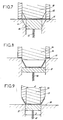
- the part 6 is then transferred to another station, comprising a guillotine shears with circular periphery which axially cuts, in the vertical direction 8, the external periphery of the frustoconical stamp 6.
- the outer edge 9 of the stamped part 6 forms an angle equal to the above-mentioned value ⁇ with its flank or apothem 7.
- the stamp 6 is then transferred to a fourth station, where its side 7 is straightened axially, that is to say vertically: this side 7 then becomes circular cylindrical and perpendicular to the bottom 5 of the stamp.
- This side 7 is then provided with an external chamfer 3 of angle ⁇ , which is the result that we aim to obtain.
- the piece 6 obtained is then optionally passed through a calibration station, then is made, on a last station ( Figure 6), the central hole 2 for passage of the drive shaft of the cup.
- the tools used for cutting the disc 4 ( Figure 2) and for drilling the hole 2 ( Figure 6) are conventional tools operating as a cookie cutter. They are therefore not represented.
- FIG. 7 shows the tool used for stamping, according to FIG. 3, the frustoconical part 6 from the disc 4.
- This tool comprises a complementary punch 10 and a matrix 11, of frustoconical shape.
- a conventional sidewall press 12 comes to press strongly on the periphery of the disc 4 in order to maintain it during stamping, which prevents the material from wrinkling.
- an extraction pusher 24, pushed upwards by an axial spring 13, equips the die 11.
- FIG. 8 The tool allowing the axial sectioning, according to FIG. 4, of the periphery of the stamping 6, is represented in FIG. 8. It is a circular cutting tool comprising a circular cylindrical punch 14, an associated die 15, a press -wall 16, and an extraction pusher 17 pushed back by a spring 18.
- the tool used for straightening according to FIG. 5 is represented in FIG. 9. It comprises a beveled flank press 19, a circular cylindrical matrix, of diameter D equal to the external diameter of the cup 1 to be obtained, a pusher 21 with spring. 22, and a circular cylindrical punch 23, of diameter d equal to the inside diameter of the aforementioned cup 1.
Landscapes
- Engineering & Computer Science (AREA)
- Mechanical Engineering (AREA)
- Forging (AREA)
- Shaping Metal By Deep-Drawing, Or The Like (AREA)
- Superconductors And Manufacturing Methods Therefor (AREA)
- Photoreceptors In Electrophotography (AREA)
- Metal Extraction Processes (AREA)
- Containers And Plastic Fillers For Packaging (AREA)
- Processing Of Meat And Fish (AREA)
- Adornments (AREA)
- Polishing Bodies And Polishing Tools (AREA)
Claims (4)
- Verfahren zur Herstellung einer äußeren Schrägkante (3) an einem zylindrischen Hohlteil, ausgehend von einem ebenen Metallblech,
dadurch gekennzeichnet,- daß zunächst eine konische Vorhöhlung (6) des herzustellenden Teils unter Verwendung eines Stempels (10) hergestellt wird, dessen Höhlung die Form -eines Kegelstumpfes hat, dessen Konuswinkel (α) im wesentlichen gleich demjenigen der herzustellenden Schrägkante (3) ist, einschließlich einem ebenen Umfangsflansch,- worauf der Umfang des kegelstumpfförmigen Hohlteils (6) axial geschnitten wird,- daß in einem letzten Schritt die kegelstumpfförmige Seitenwand (7) des Hohlteils (6) aufgerichtet wird zwecks Herstellung einer Schale (1) mit koaxialer Wand, deren Kante nunmehr eine äußere Schrägkante (3) hat. - Verfahren nach Anspruch 1,
dadurch gekennzeichnet,
daß der Flansch oder die Fläche (7) des Kegelstumpfs (6) eine konstante Länge hat, die im wesentlichen gleich der Höhe (H) der herzustellenden Schale (1) ist, und daß die kleine Basis (5) dieses Teils einen Durchmesser gleich demjenigen des Bodens der Schale (1) hat. - Verfahren nach Anspruch 1 oder 2,
dadurch gekennzeichnet,
daß die drei Verfahrensschritte nacheinander an drei unterschiedlichen Stationen durchgeführt werden, die jeweils ein Werkzeug mit Stempel und Matrize haben, wobei ein Transport von einer Station zur nächsten durchgeführt wird. - Verfahren nach Anspruch 1,
dadurch gekennzeichnet,
daß die erste Phase durch ein Ausbauchen zwischen einem Stempel (10) und einer kegelstumpfförmigen Matrize (11) durchgeführt wird, daß die zweite Phase durch einen Stempel (14) und einer Matritze (15) durchgeführt wird, die einen Schneidvorgang ausüben, und daß die dritte Phase unter Verwendung eines abgeschrägten Preßflansches (19), eines Stempels (23) und einer Matrize (20) durchgeführt wird, die zylindrisch sind, wobei der Stempel (23) einen Durchmesser (d) hat, der kleiner ist als derjenige (D) der Matrize (20).
Priority Applications (1)
| Application Number | Priority Date | Filing Date | Title |
|---|---|---|---|
| AT89420120T ATE81804T1 (de) | 1988-04-06 | 1989-03-31 | Verfahren zur herstellung einer aeusseren schraegkante an einem zylindrischen ziehteil. |
Applications Claiming Priority (2)
| Application Number | Priority Date | Filing Date | Title |
|---|---|---|---|
| FR8804971 | 1988-04-06 | ||
| FR8804971A FR2629742B1 (fr) | 1988-04-06 | 1988-04-06 | Procede de realisation d'un chanfrein exterieur sur une piece cylindrique emboutie |
Publications (2)
| Publication Number | Publication Date |
|---|---|
| EP0336862A1 EP0336862A1 (de) | 1989-10-11 |
| EP0336862B1 true EP0336862B1 (de) | 1992-10-28 |
Family
ID=9365324
Family Applications (1)
| Application Number | Title | Priority Date | Filing Date |
|---|---|---|---|
| EP89420120A Expired - Lifetime EP0336862B1 (de) | 1988-04-06 | 1989-03-31 | Verfahren zur Herstellung einer äusseren Schrägkante an einem zylindrischen Ziehteil |
Country Status (8)
| Country | Link |
|---|---|
| US (1) | US4910989A (de) |
| EP (1) | EP0336862B1 (de) |
| AT (1) | ATE81804T1 (de) |
| CA (1) | CA1289418C (de) |
| DE (1) | DE68903291T2 (de) |
| ES (1) | ES2035619T3 (de) |
| FR (1) | FR2629742B1 (de) |
| GR (1) | GR3006221T3 (de) |
Families Citing this family (12)
| Publication number | Priority date | Publication date | Assignee | Title |
|---|---|---|---|---|
| EP0466958B1 (de) * | 1990-07-19 | 1992-06-03 | Degussa Aktiengesellschaft | Oberflächenmodifizierte Siliciumdioxide |
| US5755132A (en) * | 1996-02-26 | 1998-05-26 | Karl Marbach Gmbh & Co. | Punching and forming tool |
| DE29611523U1 (de) * | 1996-02-26 | 1996-08-29 | Karl Marbach GmbH & Co., 74080 Heilbronn | Stanz- und Formwerkzeug |
| CA2675504A1 (en) * | 2005-10-11 | 2007-04-19 | Iron Mount Corporation | Containers and method and apparatus for forming containers |
| CN101628409B (zh) * | 2008-07-15 | 2011-06-22 | 施俊兆 | 金属工具盒的成型方法 |
| CN102139436B (zh) * | 2010-01-29 | 2013-08-14 | 江苏白雪电器股份有限公司 | 一种金属防护罩的加工方法 |
| CN102615184A (zh) * | 2012-04-04 | 2012-08-01 | 无锡欧易博阀业科技有限公司 | 盘状工件拉伸模具 |
| CN102974976A (zh) * | 2012-11-15 | 2013-03-20 | 重庆黄龙机械制造有限公司 | 金属周转箱的制作方法 |
| CN104428102A (zh) * | 2013-03-04 | 2015-03-18 | 丁玉武 | 一种汽车钢圈轮辐生产制造工艺及其专用模具 |
| CN104384844A (zh) * | 2014-10-08 | 2015-03-04 | 柳州科尔特锻造机械有限公司 | 一种工程机械钢圈轮辐生产工艺 |
| CN111822942B (zh) * | 2019-04-22 | 2022-04-29 | 安克创新科技股份有限公司 | 装饰网的加工方法 |
| CN112808858B (zh) * | 2021-01-25 | 2022-11-15 | 重庆理工大学 | 用于制作弹簧抱挎的级进模 |
Family Cites Families (10)
| Publication number | Priority date | Publication date | Assignee | Title |
|---|---|---|---|---|
| US161634A (en) * | 1875-04-06 | Improvement in methods of producing flanged lids and collars for sheet-metal cans | ||
| US448748A (en) * | 1891-03-24 | Method of and machine for making cup-shaped articles | ||
| US2321085A (en) * | 1941-11-06 | 1943-06-08 | Electromaster Inc | Method for producing drawn cups with faced and beveled edges |
| US2415940A (en) * | 1944-10-05 | 1947-02-18 | Remington Arms Co Inc | Metal cupping process |
| US2611475A (en) * | 1948-10-07 | 1952-09-23 | Remington Arms Co Inc | Cup drawing apparatus |
| US3406554A (en) * | 1965-07-06 | 1968-10-22 | Continental Can Co | Apparatus for and method of forming containers |
| DE1932139A1 (de) * | 1969-06-25 | 1971-01-21 | Dynamit Nobel Ag | Verfahren zur Herstellung tiefgezogener Hohlkoerper |
| SU590053A1 (ru) * | 1976-05-10 | 1978-01-30 | Ижевский механический институт | Способ получени кольцевых деталей |
| SU1016008A1 (ru) * | 1980-07-14 | 1983-05-07 | Предприятие П/Я М-5344 | Способ получени полых изделий с выступом на дне |
| US4534201A (en) * | 1982-12-29 | 1985-08-13 | American Can Company | Undercut punch to control ironing |
-
1988
- 1988-04-06 FR FR8804971A patent/FR2629742B1/fr not_active Expired - Fee Related
-
1989
- 1989-03-30 CA CA000595247A patent/CA1289418C/fr not_active Expired - Lifetime
- 1989-03-31 AT AT89420120T patent/ATE81804T1/de not_active IP Right Cessation
- 1989-03-31 ES ES198989420120T patent/ES2035619T3/es not_active Expired - Lifetime
- 1989-03-31 DE DE8989420120T patent/DE68903291T2/de not_active Expired - Fee Related
- 1989-03-31 EP EP89420120A patent/EP0336862B1/de not_active Expired - Lifetime
- 1989-04-03 US US07/332,564 patent/US4910989A/en not_active Expired - Fee Related
-
1992
- 1992-11-12 GR GR920402557T patent/GR3006221T3/el unknown
Also Published As
| Publication number | Publication date |
|---|---|
| US4910989A (en) | 1990-03-27 |
| DE68903291T2 (de) | 1993-06-17 |
| GR3006221T3 (de) | 1993-06-21 |
| ES2035619T3 (es) | 1993-04-16 |
| EP0336862A1 (de) | 1989-10-11 |
| ATE81804T1 (de) | 1992-11-15 |
| FR2629742B1 (fr) | 1994-01-14 |
| FR2629742A1 (fr) | 1989-10-13 |
| CA1289418C (fr) | 1991-09-24 |
| DE68903291D1 (de) | 1992-12-03 |
Similar Documents
| Publication | Publication Date | Title |
|---|---|---|
| EP0336862B1 (de) | Verfahren zur Herstellung einer äusseren Schrägkante an einem zylindrischen Ziehteil | |
| BE1003541A3 (fr) | Procede et appareil pour former des panneaux d'extremites de recipients. | |
| EP0363285B1 (de) | Leicht zu öffnende Flaschenkapsel aus Aluminiumfolie sowie Verfahren zu ihrer Herstellung | |
| FR2548090A1 (fr) | Procede pour former par extrusion a froid un culot de bougie d'allumage | |
| EP0514249B1 (de) | Verfahren zur Herstellung eines Rohrbündelwärmetauschers | |
| EP0310726B1 (de) | Verfahren zum Herstellen konischer Metalldosen und Werkzeug zur Durchführung des Verfahrens | |
| CA2031859C (fr) | Procede et dispositif d'emboutissage de recipients de forme tronconique, et recipient ainsi embouti | |
| FR2515885A1 (fr) | Procede de production d'une electrode composite pour bougie d'allumage et cette electrode | |
| EP0099306B1 (de) | Verfahren und Vorrichtung zum Herstellen von Kunststoffgegenständen, die durch leicht trennbare Verbindungslaschen miteinander verbunden sind, durch Thermoformen | |
| FR2631262A1 (fr) | Procede pour la production de profiles metalliques creux, et dispositif pour l'execution du procede | |
| JPH05318009A (ja) | 装飾部品の製造方法 | |
| RU2146177C1 (ru) | Способ прессования труб большого диаметра | |
| CH500024A (fr) | Procédé de fabrication de produits métalliques par emboutissage | |
| CH103565A (fr) | Procédé et machine pour la fabrication d'une ébauche de tube compressible et ébauche obtenue par ledit procédé. | |
| FR2659035A1 (fr) | Procede de decoupage de pieces metalliques et moyens pour sa mise en óoeuvre. | |
| BE507071A (de) | ||
| FR2469230A1 (fr) | Procede de fabrication d'un element filete et dispositif pour la mise en oeuvre de ce procede | |
| FR2709111A1 (fr) | Barquette métallique notamment en acier à deux compartiments et procédé de fabrication de ce type de barquettes. | |
| BE464669A (de) | ||
| BE533351A (de) | ||
| BE528289A (de) | ||
| BE508433A (de) | ||
| BE481743A (de) | ||
| BE504757A (de) | ||
| FR2761632A1 (fr) | Procede de formage d'un alesage muni d'une portee a vis et piece ainsi obtenue |
Legal Events
| Date | Code | Title | Description |
|---|---|---|---|
| PUAI | Public reference made under article 153(3) epc to a published international application that has entered the european phase |
Free format text: ORIGINAL CODE: 0009012 |
|
| AK | Designated contracting states |
Kind code of ref document: A1 Designated state(s): AT BE CH DE ES FR GB GR IT LI LU NL SE |
|
| 17P | Request for examination filed |
Effective date: 19900120 |
|
| RAP1 | Party data changed (applicant data changed or rights of an application transferred) |
Owner name: A2C GROUPE PRATIC-ADEMVA |
|
| 17Q | First examination report despatched |
Effective date: 19920318 |
|
| RTI1 | Title (correction) | ||
| GRAA | (expected) grant |
Free format text: ORIGINAL CODE: 0009210 |
|
| ITF | It: translation for a ep patent filed | ||
| AK | Designated contracting states |
Kind code of ref document: B1 Designated state(s): AT BE CH DE ES FR GB GR IT LI LU NL SE |
|
| PG25 | Lapsed in a contracting state [announced via postgrant information from national office to epo] |
Ref country code: GR Free format text: LAPSE BECAUSE OF FAILURE TO SUBMIT A TRANSLATION OF THE DESCRIPTION OR TO PAY THE FEE WITHIN THE PRESCRIBED TIME-LIMIT Effective date: 19921028 |
|
| REF | Corresponds to: |
Ref document number: 81804 Country of ref document: AT Date of ref document: 19921115 Kind code of ref document: T |
|
| REF | Corresponds to: |
Ref document number: 68903291 Country of ref document: DE Date of ref document: 19921203 |
|
| GBT | Gb: translation of ep patent filed (gb section 77(6)(a)/1977) | ||
| PG25 | Lapsed in a contracting state [announced via postgrant information from national office to epo] |
Ref country code: LU Free format text: LAPSE BECAUSE OF NON-PAYMENT OF DUE FEES Effective date: 19930331 Ref country code: LI Effective date: 19930331 Ref country code: GB Effective date: 19930331 Ref country code: CH Effective date: 19930331 Ref country code: BE Effective date: 19930331 Ref country code: AT Effective date: 19930331 |
|
| PG25 | Lapsed in a contracting state [announced via postgrant information from national office to epo] |
Ref country code: SE Effective date: 19930401 Ref country code: ES Free format text: LAPSE BECAUSE OF NON-PAYMENT OF DUE FEES Effective date: 19930401 |
|
| REG | Reference to a national code |
Ref country code: ES Ref legal event code: FG2A Ref document number: 2035619 Country of ref document: ES Kind code of ref document: T3 |
|
| REG | Reference to a national code |
Ref country code: GR Ref legal event code: FG4A Free format text: 3006221 |
|
| PLBE | No opposition filed within time limit |
Free format text: ORIGINAL CODE: 0009261 |
|
| STAA | Information on the status of an ep patent application or granted ep patent |
Free format text: STATUS: NO OPPOSITION FILED WITHIN TIME LIMIT |
|
| BERE | Be: lapsed |
Owner name: A2C GROUPE PRATIC-ADEMVA Effective date: 19930331 |
|
| PG25 | Lapsed in a contracting state [announced via postgrant information from national office to epo] |
Ref country code: NL Effective date: 19931001 |
|
| 26N | No opposition filed | ||
| NLV4 | Nl: lapsed or anulled due to non-payment of the annual fee | ||
| REG | Reference to a national code |
Ref country code: CH Ref legal event code: PL |
|
| GBPC | Gb: european patent ceased through non-payment of renewal fee |
Effective date: 19930331 |
|
| REG | Reference to a national code |
Ref country code: GR Ref legal event code: MM2A Free format text: 3006221 |
|
| EUG | Se: european patent has lapsed |
Ref document number: 89420120.1 Effective date: 19931110 |
|
| PGFP | Annual fee paid to national office [announced via postgrant information from national office to epo] |
Ref country code: DE Payment date: 19980218 Year of fee payment: 10 |
|
| PGFP | Annual fee paid to national office [announced via postgrant information from national office to epo] |
Ref country code: FR Payment date: 19980305 Year of fee payment: 10 |
|
| REG | Reference to a national code |
Ref country code: ES Ref legal event code: FD2A Effective date: 19990503 |
|
| PG25 | Lapsed in a contracting state [announced via postgrant information from national office to epo] |
Ref country code: FR Free format text: LAPSE BECAUSE OF NON-PAYMENT OF DUE FEES Effective date: 19991130 |
|
| REG | Reference to a national code |
Ref country code: FR Ref legal event code: ST |
|
| PG25 | Lapsed in a contracting state [announced via postgrant information from national office to epo] |
Ref country code: DE Free format text: LAPSE BECAUSE OF NON-PAYMENT OF DUE FEES Effective date: 20000101 |
|
| PG25 | Lapsed in a contracting state [announced via postgrant information from national office to epo] |
Ref country code: IT Free format text: LAPSE BECAUSE OF NON-PAYMENT OF DUE FEES;WARNING: LAPSES OF ITALIAN PATENTS WITH EFFECTIVE DATE BEFORE 2007 MAY HAVE OCCURRED AT ANY TIME BEFORE 2007. THE CORRECT EFFECTIVE DATE MAY BE DIFFERENT FROM THE ONE RECORDED. Effective date: 20050331 |