EP0339829A2 - Kontinuierliches selbstnachtränkendes Farbbandkassettensystem - Google Patents
Kontinuierliches selbstnachtränkendes Farbbandkassettensystem Download PDFInfo
- Publication number
- EP0339829A2 EP0339829A2 EP89303630A EP89303630A EP0339829A2 EP 0339829 A2 EP0339829 A2 EP 0339829A2 EP 89303630 A EP89303630 A EP 89303630A EP 89303630 A EP89303630 A EP 89303630A EP 0339829 A2 EP0339829 A2 EP 0339829A2
- Authority
- EP
- European Patent Office
- Prior art keywords
- ribbon
- wick
- ink
- chamber
- further characterized
- Prior art date
- Legal status (The legal status is an assumption and is not a legal conclusion. Google has not performed a legal analysis and makes no representation as to the accuracy of the status listed.)
- Withdrawn
Links
Images


Classifications
-
- B—PERFORMING OPERATIONS; TRANSPORTING
- B41—PRINTING; LINING MACHINES; TYPEWRITERS; STAMPS
- B41J—TYPEWRITERS; SELECTIVE PRINTING MECHANISMS, i.e. MECHANISMS PRINTING OTHERWISE THAN FROM A FORME; CORRECTION OF TYPOGRAPHICAL ERRORS
- B41J31/00—Ink ribbons; Renovating or testing ink ribbons
- B41J31/14—Renovating or testing ink ribbons
- B41J31/16—Renovating or testing ink ribbons while fitted in the machine using the ink ribbons
-
- B—PERFORMING OPERATIONS; TRANSPORTING
- B41—PRINTING; LINING MACHINES; TYPEWRITERS; STAMPS
- B41J—TYPEWRITERS; SELECTIVE PRINTING MECHANISMS, i.e. MECHANISMS PRINTING OTHERWISE THAN FROM A FORME; CORRECTION OF TYPOGRAPHICAL ERRORS
- B41J32/00—Ink-ribbon cartridges
- B41J32/02—Ink-ribbon cartridges for endless ribbons
Definitions
- This invention relates to printing ribbon cartridges and more particularly to printing ribbon cartridges characterized by a continuous, self-inking ribbon cartridge system.
- Printing ribbon spools or cartridges which include a means for replenishing the ink drawn from a printing ribbon are well known in the art. Most typically, these reinking devices comprise an inking roller impregnated with ink which is pressed against a ribbon. Other ribbon spools have a liquid ink reservoir with a wick placed in contact with a ribbon.
- spools or cartridges characterized by a roller mechanism include the reinking device disclosed in U.S. Patent No. 4,653,947.
- the '197 device includes a rotatable pinch roller mounted on an inker case, a force ink-impregnated inking roller tangent to the pinch roller which is configured with a spring biasing mechanism to maintain a constant relation with the pinch roller.
- the inker case is pivotably mounted within the cartridge housing and the spring is biased such that the pinch roller mounted to the inker case is urged into frictional contact with the drive roller with the ribbon passing therebetween. Ink is passed to the ribbon as the ribbon is pulled between the pinch and ink rollers.
- the '947 reinking cartridge is exemplary of roller type reinking devices of the prior art. All roller type devices are characterized by an ink-pregnated ribbon placed in a cartridge or on a spool. The ink is somewhat replenished as it is drawn past the ink roller. Most importantly, that portion of the ribbon in contact with the roller will become soaked with excessive ink because the ribbon is in continuous contact with the ink-impregnated roller all of the time, even when the printer is not in use. Consequently, characters printed for a time after the printer has restarted will be nonuniform (excessively dark), lowering the print quality of the document.
- roller type reinking cartridges have a finite shelf life, since the reinking roller begins to dry as soon as the cartridge leaves the factory. Lastly, there is no control over the amount of ink which is provided to the ribbon. When the inking cartridge is fresh an unnecessary large quantity of ink will be provided to the ribbon and, as the cartridge ages, the ribbon will provide an undesirably small quantity of ink.
- a ribbon cartridge device it would be advantageous for a ribbon cartridge device to provide a continuous self-inking of the ribbon.
- This device should not be susceptible to leakage and should be easily adapted for use in a variety of cartridge type printing machines.
- the present invention is directed towards such a ribbon cartridge.
- An object of the present invention is to provide for a ribbon cartridge system which provides continuous self-inking of a ribbon, and/or a ribbon cartridge system which is easily adaptable to existing printing device configurations, and/or a ribbon cartridge system that generates characters of uniform print density, and/or a closed ribbon cartridge system having an ink reservoir which recirculates excessive ink, avoiding any ink leakage, and/or a ribbon cartridge having an ink reservoir which can be used at any angle, and/or a ribbon cartridge system whose print quality is controlled with an air ink exchange mechanism that is configured in accordance with the printer speed, and/or a ribbon cartridge system which provides ink to the ribbon only when the printer is in use, and/or a ribbon cartridge system which is contained in an insert to be configured in a convention ribbon cartridge case or shell, and/or to provide improvements in such apparatus generally.
- a reservoir element for use with a ribbon cartridge having a case and further having an endless ribbon circulating therein includes a container having liquid ink initially sealed in a first chamber and a means for enabling the ink to flow into a second container chamber.
- a wick is configured with the second container chamber to controllably present ink at the exterior of the container after the second chamber receives the ink.
- a ribbon cartridge system for use with a printing device includes an endless ribbon and a case for receiving the ribbon.
- the case is adapted to be received by the printing device so as to enable the ribbon to be advanced while the printing device is in use.
- a plurality of rollers guide the ribbon to and from the case.
- An ink reservoir element is also included, and comprises a container having liquid ink initially sealed in a first chamber, and includes a means for selectively enabling the ink to flow into a second container chamber.
- a wick is configured with the second container chamber to controllably present the ink at the exterior of the container. After the seal between the first and second container chamber is broken, the ink migrates to the second chamber and saturates the wick.
- An apparatus provides that excess ink is recirculated back from the wick, eliminating any possibility of drippage.
- a ribbon tensioning apparatus is included in the case and is configured to allow the ribbon to communicate with the wick only when the ribbon is advanced by the printing device.
- FIG. 1 there is a top illustration of a ribbon cartridge 10 provided according to the present invention.
- the ribbon cartridge 10 has a conventional external configuration and is adapted for use with a variety of conventional printers and is therefore interchangeable with a variety of existing ribbon cartridges, such as an Epson RX-100, FX-100, a Burroughs AP1354 or Newcoat BM 153.
- existing ribbon cartridges such as an Epson RX-100, FX-100, a Burroughs AP1354 or Newcoat BM 153.
- a ribbon cartridge provided according to the present invention is easily adapted in accordance with the intended printer application.
- the ribbon cartridge 10 is exemplary of endless ribbon type cartridges used with computer printers, teleprinters and typewriters.
- a ribbon 12 extends between roller assemblies 14 and 16 which hold the ribbon in a spaced relation with re spect to a body 18.
- a receiving roller assembly 20 comprised of first and second tension rollers 22 and 24.
- An extended portion of the first roller 22 is received by an advancing mechanism in the printer, not shown and not part of the present invention.
- the roller 22 is rotated in a counterclockwise manner to advance ribbon 12 from right to left.
- Roller 24 is urged against roller 22 by a spring 26, as is well known in the art.
- the ribbon is of an endless type and is fed into a cavity 28 in a well known manner.
- the tensioning apparatus comprises a spring 32 which urges a cylinder 34 against a rear wall 36 of the cartridge body.
- the ribbon passes therebetween.
- the spring and cylinder combination is laterally located by retaining walls 38 and 40.
- ink reservoir 42 provides ink in a selectively controlled, continuous fashion through wick 44 only when the printer in use.
- Ribbon positioning mechanism 46 is configured to maintain the position of the ribbon against the cartridge back wall when the printer is idle.
- the spring mechanism in the preferred embodiment comprises a longitudinally wound coil spring 48 positioned with post 50.
- FIG. 3 there is a top view of a portion of the ribbon cartridge of Fig. 1.
- ribbon 12 is shown in a first position 52 in which spring 48 exerts a force against the ribbon to maintain it approximately against the back wall 36 of the ribbon cartridge.
- spring 48 exerts a force against the ribbon to maintain it approximately against the back wall 36 of the ribbon cartridge.
- a second position 54 shown in broken line, communicating with the wick.
- the magnitude of the force exerted by spring 48 against the ribbon is preferably configured to be less than or equal to that force produced by the rotation of the roller 22, so that when the ribbon is advanced, it simultaneously moves away from the back wall to engage the wick 44.
- the ribbon automat strictlyically is withdrawn from the wick.
- the magnitude of the restoring force generated by spring 48 should be selected in accordance with the magnitude of the force exerted by spring 32. Too small a force exerted by spring 32 will produce insufficient tension in the ribbon by the action of cylinder 34 to allow the ribbon to be moved in contact with the wick. Too large a force will prevent the ribbon from being displaced from the wick at all.
- the ribbon cartridge system is equivalent to an Epson MX- 100 and spring 48 is configured to provide a ribbon displacement force of approximately 28-40 grams, while the force exerted by spring 32 is substantially between 13 to 17 grams.
- ink from the reservoir is supplied to a portion of the printing surface of the ribbon by means of capillary action.
- the ink subsequently dissipates locally throughout the printing surface of the ribbon in a uniform, even manner.
- Continuous application of ink, coupled with its distribution throughout the printing surface of the ribbon ensures that print quality will always be uniform, no matter what portion of the ribbon is printing and irrespective of the age of the cartridge.
- the ribbon positioning mechanism 46 which provides for selective engagement of the ribbon with the wick only when the cartridge is in operation marks a point of departure of the present invention over the prior art.
- Known ribbon printing devices which have employed liquid reservoirs have maintained the ribbon in contact with the ink source. This has resulted in a premature draining of ink in the reservoir, as well as an undesirable super saturation of that portion of the printing ribbon in prolonged contact with the wick. Ink leakage has been the result.
- the present ribbon cartridge provides ink to the ribbon only when the cartridge is actually in use thereby avoiding all leakage.
- the ink reservoir 42 of Fig. 1 is characterized by first and second cavities or chambers formed in reservoir case portions 56 and 58.
- the reservoir also includes a seal 60 which is placed therebetween.
- An additional seal 62 may also be included during fabrication as is required.
- the ink reservoir is configured so that, when assembled, the reservoir case 42 is inverted from the position illustrated in the Fig. 4. Liquid ink is provided to the cavity or chamber in case portion 56 with seals 60 and 62 positioned therewith before case portion 58 and wick 44 are provided. When assembled, the ink reservoir contains only ink in the first cavity formed within the case portion 56, even when inverted.
- pin 64 positioned within the case portion 56, is displaced to puncture weakened section 66 in the seal, thereby allowing ink to flow into the lower cavity formed within case portion 58 and ultimately saturating the wick with ink.
- a conventional wick may be used, it is preferable to employ a commercially available spunbonded polyester fibrous material of 0.027 wick thickness made by DuPont Company under the trademark Relmay , part No. 2470.
- the lower case portion forms a chamber that is preferably comprised of a sequence of two channels 68 and 70.
- the channel 68 is interior to the channel 70, and acts as an ink supply channel to the wick.
- the outer channel 70 is a recirculation channel and extends up from underneath the wick, allowing ink which has propagated to the exterior wick portion to return to the interior. Air is allowed to enter into the ink reservoir interior cavities via channel 72 configured to connect the interior supply channel with the exterior return channel. The surface area of the air channel controls the rate of ink transfer to the wick.
- the air exchange mechanism can include a plurality of air channels connecting the channels 68 and 70 adjacent to and in conjunction with channel 72.
- the ribbon cartridge system having a reservoir as described here and above comprises a closed system that includes an ink reservoir and the wick.
- the wick is supplied by at least one channel and includes a second return channel such that the ink is constantly flowing from the reservoir through the wick and back to the reservoir again.
- a ribbon cartridge system provided according to the present invention can be configured for use with standard ink, but it is preferable that a polymer based ink, such as that made by Image Specialist of Hauppauge, N.Y., be employed. That ink has the following characteristics: Pigment 0-5% Viscosity 100-500 centipoise Dye 10-30% Fatty acid 5-15% Mineral Oil 0-10% Vegetable Oil 5-20% Glycol ether ester 0-25% Fatty amide 0-3% Fatty aliphatic naphtha 0-5%
- This polymer based ink can be configured with 1200 CPS to 200 CPS having a surface tension index between 40 to 45; as opposed to standard abrasive ink which has a surface tension index of 30 to 35.
- the viscosity of the ink can be adjusted to allow for operation of the printer in other than horizontal position.
- the ribbon cartridge 10 can be operated at angles up to 45o without any leakage of the ink from the reservoir.
- appropriate adjustments to the viscosity of the ink can be made to operate the printer at angles up to and including vertical without any leakage of ink.
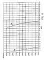
- a ribbon cartridge system provided by the present invention allows for a substantial increase in both the quality of the printed characters as well as the number of characters that can be printed.
- the number of characters which can be printed with the ribbon cartridge system is limited solely by the amount of ink contained in the reservoir.
- the ribbon cartridge system of Fig. 1 will print at least five times the number of characters as would a conventional roller based ribbon cartridge.
- Curve 74 indicates character darkness as a function of the number of times for known ribbon cartridges. These known ribbon cartridges provide an essentially linear degradation of character darkness beginning from almost the first character.
- a ribbon cartridge provide according to the present invention, provides us characters of essentially constant print darkness over almost the entire life of the ribbon cartridge (curve 76). This dramatic increase in performance is because of the several reasons cited above:
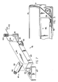
- FIG. 7 there is shown an exploded perspective illustration of an insert ribbon cartridge system 78 provided according to the present invention.
- the insert system includes the components found in the ribbon cartridge system of Fig. 1 but are configured as a replaceable insert adapted to be received by a conventional shell or casing, detailed hereinafter with respect to Fig. 8.
- the insert system 78 is characterized by a one piece housing 80 that is typically molded to have an exterior shape that conforms to an interior surface of a particular shell or casing.
- a ribbon tensioning mechanism 84 comprising a spring 86 and cylinder 88 is received by a recess 90 formed in the plastic housing.
- the system 78 includes an internal ink reservoir of the type described hereinabove with respect to Fig. 4 providing ink through a wick 82.
- An opening 93 receives a pin (not shown) to puncture an internal seal allowing ink to flow from an upper ink reservoir cavity to a lower ink reservoir cavity thereby saturating the wick with ink.
- the insert is also characterized by an extension 96 which spaces a post 98 from the main body of the housing 80 and is configured to receive a spring 100 that comprises a ribbon positioning mechanism 102.
- the coaxial spring has a first end 104 which contacts a portion of the casing detailed with respect to Fig. 8 and a second portion 106 which extends outward from the post to receive and position the ribbon as described hereinabove.
- the one end 104 of the spring which contacts the casing interior surface can be located by a portion of the extension 96.
- the insert also comprises an end section 107 which is adapted to the particular interior configuration of the conventional casing or shell and may aid in guiding the ribbon to the ribbon tensioning mechanism.
- Fig. 8 there is shown a top illustration of a portion of a casing or shell 108.
- the casing 108 is conventional, and is adapted to be received by a particular printing device. Therefore, such conventional components as rollers 112 and 114 for advancing ribbon 116 are included.
- Ribbon 114 is endless, and is stored in a first casing cavity 118. Only a portion of the ribbon and first cavity are shown for purposes of clarity.
- the ribbon is positioned randomly in the first cavity for storage and subsequently exits the first cavity at opening 120.
- the first cavity is bounded by an interior wall 122.
- the casing or shell is characterized by a second cavity 124 which may or may not contain additional wall portions (not shown) which are used to locate the ribbon as it traverses the second cavity and is received by roller 124.
- the insert 78 is received in this second cavity portion and, as noted, has an exterior geometry adapted to be received by a shell or casing second cavity. In some applications, this may require modification to the interior wall portions but typically the insert housing can be easily formed to accommodate the interior geometry of the second cavity such that the insert can be directly affixed to casing bottom surface 126 without modification.
- the magnitude of the forces exerted by the springs associated with the ribbon tensioning and ribbon positioning mechanisms 84 and 102, respectively, are cooperatively determined in a manner described here inabove to ensure that the ribbon will be positioned against the wick only when the printing device is in operation (i.e. when the ribbon is being advanced) and spaced from the wick when the printing device is idle.
- the installation of the insert 78 is simple and direct. Since the insert can be readily configured to the interior geometries of existing ribbon cartridges, an insert can be configured for each given ribbon cartridge configuration. As a result, the need for replacing whole ribbon cartridges is eliminated.
Landscapes
- Impression-Transfer Materials And Handling Thereof (AREA)
Applications Claiming Priority (4)
| Application Number | Priority Date | Filing Date | Title |
|---|---|---|---|
| US18584488A | 1988-04-25 | 1988-04-25 | |
| US185844 | 1988-04-25 | ||
| US243243 | 1988-09-08 | ||
| US07/243,243 US4988225A (en) | 1988-04-25 | 1988-09-08 | Continuous self-inking ribbon cartridge system |
Publications (2)
| Publication Number | Publication Date |
|---|---|
| EP0339829A2 true EP0339829A2 (de) | 1989-11-02 |
| EP0339829A3 EP0339829A3 (de) | 1990-03-14 |
Family
ID=26881531
Family Applications (1)
| Application Number | Title | Priority Date | Filing Date |
|---|---|---|---|
| EP89303630A Withdrawn EP0339829A3 (de) | 1988-04-25 | 1989-04-12 | Kontinuierliches selbstnachtränkendes Farbbandkassettensystem |
Country Status (3)
| Country | Link |
|---|---|
| US (1) | US4988225A (de) |
| EP (1) | EP0339829A3 (de) |
| JP (1) | JPH01316285A (de) |
Cited By (2)
| Publication number | Priority date | Publication date | Assignee | Title |
|---|---|---|---|---|
| EP0525114A4 (en) * | 1990-04-19 | 1993-05-19 | Wei T. Cheng | Ribbon cartridge with ink wicking mechanism |
| EP2149456A1 (de) * | 2008-07-30 | 2010-02-03 | Oki Data Corporation | Tintenbandkartusche und Druckvorrichtung |
Families Citing this family (2)
| Publication number | Priority date | Publication date | Assignee | Title |
|---|---|---|---|---|
| US5052833A (en) * | 1990-11-09 | 1991-10-01 | Jing Tech, Inc. | Self-inking continuous ribbon cartridge system |
| US5399033A (en) * | 1994-01-13 | 1995-03-21 | Pelikan, Inc. | Re-inkable ribbon cartridge |
Family Cites Families (9)
| Publication number | Priority date | Publication date | Assignee | Title |
|---|---|---|---|---|
| US2969865A (en) * | 1960-05-16 | 1961-01-31 | Dennison Mfg Co | Printing machine having ink-ribbon reinking means |
| JPS585766B2 (ja) * | 1974-10-29 | 1983-02-01 | テイジンカセイ カブシキガイシヤ | ガラスセンイキヨウカネツカソセイジユシソセイブツノ ペレツトセイゾウホウホウ |
| US4153378A (en) * | 1975-11-18 | 1979-05-08 | Franz Buttner Ag. | Re-inking and ventilation control for inked ribbon cassette |
| IT1159918B (it) * | 1978-10-03 | 1987-03-04 | Honeywell Inf Systems | Cartuccia a nastro inchiostrato senza fine con cartuccia di reinchiostrazione intercambiabile |
| JPS6044384A (ja) * | 1983-08-22 | 1985-03-09 | エヌ・シー・アール・コーポレーション | インキ供給機構付リボン・カ−トリツジ |
| US4639153A (en) * | 1984-07-09 | 1987-01-27 | Jing Tech, Inc. | Printing ribbon spool having an ink reservoir and method of making same |
| JPS61211074A (ja) * | 1985-03-15 | 1986-09-19 | Nec Corp | リボンカセツトのインクタンク |
| IT1187942B (it) * | 1986-02-28 | 1987-12-23 | Olivetti & Co Spa | Cartucce per nastro inchiostrato con dispositivo di reinchiostrazione |
| IT207529Z2 (it) * | 1986-03-10 | 1988-01-25 | Olivetti & Co Spa | Cartuccia per un nastro inchiostrato con tampone di reichiostrazione |
-
1988
- 1988-09-08 US US07/243,243 patent/US4988225A/en not_active Expired - Fee Related
-
1989
- 1989-04-12 EP EP89303630A patent/EP0339829A3/de not_active Withdrawn
- 1989-04-25 JP JP1103564A patent/JPH01316285A/ja active Pending
Cited By (5)
| Publication number | Priority date | Publication date | Assignee | Title |
|---|---|---|---|---|
| EP0525114A4 (en) * | 1990-04-19 | 1993-05-19 | Wei T. Cheng | Ribbon cartridge with ink wicking mechanism |
| EP2149456A1 (de) * | 2008-07-30 | 2010-02-03 | Oki Data Corporation | Tintenbandkartusche und Druckvorrichtung |
| CN101659165A (zh) * | 2008-07-30 | 2010-03-03 | 日本冲信息株式会社 | 墨带盒和打印装置 |
| US8256973B2 (en) | 2008-07-30 | 2012-09-04 | Oki Data Corporation | Ink ribbon cartridge and printing apparatus |
| CN101659165B (zh) * | 2008-07-30 | 2014-05-14 | 日本冲信息株式会社 | 墨带盒和打印装置 |
Also Published As
| Publication number | Publication date |
|---|---|
| US4988225A (en) | 1991-01-29 |
| EP0339829A3 (de) | 1990-03-14 |
| JPH01316285A (ja) | 1989-12-21 |
Similar Documents
| Publication | Publication Date | Title |
|---|---|---|
| US5156472A (en) | Dot matrix printer supply system having ink absorbing member filled under reduced pressure | |
| US5607242A (en) | Ink-supply tank for a printer | |
| US4969759A (en) | Ink-supplied wire dot matrix printer head | |
| US5221148A (en) | Dot matrix printer ink supply system having ink absorbing member substantially filling an ink tank | |
| CA1224736A (en) | Ribbon cassette with re-inking mechanism | |
| DE19609879B4 (de) | Lagerbehälter zum Lagern einer Tintenstrahldruckeinheit | |
| US5156473A (en) | Multi-color cartridge ink-supply system for a dot matrix printer | |
| US5174665A (en) | Ink-supply system for a dot matrix printer | |
| US5156470A (en) | Two cartridge ink-supply system for a multi-color dot matrix printer | |
| JPH03136867A (ja) | インクタンクおよびインクジェットカートリッジならびにインクジェット装置 | |
| EP0339829A2 (de) | Kontinuierliches selbstnachtränkendes Farbbandkassettensystem | |
| EP0167892A1 (de) | Farbbandkassette | |
| JPH0523954B2 (de) | ||
| EP0606101B1 (de) | Tintenbehälter | |
| JP2570211B2 (ja) | プリンタのインクタンク | |
| JP4428022B2 (ja) | 印判 | |
| JPH09327962A (ja) | インキ補給式リボンカセット | |
| US5690438A (en) | Continuous or endless loop printing ribbon cassettes and reinking devices therefor | |
| JPS63281879A (ja) | インクリボンカセツト | |
| JP2001347738A (ja) | インクリボンカセット | |
| JPH0776102A (ja) | インクジェット装置 | |
| JPH03197167A (ja) | インキ補給式リボンカセット | |
| JP2001301290A (ja) | インクリボンカセット | |
| JPH1071729A (ja) | プリンタのインクタンク | |
| JPS60137681A (ja) | リボンシフト機構 |
Legal Events
| Date | Code | Title | Description |
|---|---|---|---|
| PUAI | Public reference made under article 153(3) epc to a published international application that has entered the european phase |
Free format text: ORIGINAL CODE: 0009012 |
|
| 17P | Request for examination filed |
Effective date: 19890503 |
|
| AK | Designated contracting states |
Kind code of ref document: A2 Designated state(s): AT BE CH DE ES FR GB GR IT LI LU NL SE |
|
| PUAL | Search report despatched |
Free format text: ORIGINAL CODE: 0009013 |
|
| AK | Designated contracting states |
Kind code of ref document: A3 Designated state(s): AT BE CH DE ES FR GB GR IT LI LU NL SE |
|
| 17Q | First examination report despatched |
Effective date: 19911223 |
|
| STAA | Information on the status of an ep patent application or granted ep patent |
Free format text: STATUS: THE APPLICATION IS DEEMED TO BE WITHDRAWN |
|
| 18D | Application deemed to be withdrawn |
Effective date: 19931103 |