EP0339883A1 - Wasserklosett mit Warmluftgebläse und Wasserklosetteinheit, befestigbar in einem Toilettenraum - Google Patents
Wasserklosett mit Warmluftgebläse und Wasserklosetteinheit, befestigbar in einem Toilettenraum Download PDFInfo
- Publication number
- EP0339883A1 EP0339883A1 EP89303990A EP89303990A EP0339883A1 EP 0339883 A1 EP0339883 A1 EP 0339883A1 EP 89303990 A EP89303990 A EP 89303990A EP 89303990 A EP89303990 A EP 89303990A EP 0339883 A1 EP0339883 A1 EP 0339883A1
- Authority
- EP
- European Patent Office
- Prior art keywords
- water closet
- warm air
- toilet room
- bowl
- adapter
- Prior art date
- Legal status (The legal status is an assumption and is not a legal conclusion. Google has not performed a legal analysis and makes no representation as to the accuracy of the status listed.)
- Granted
Links
Images













Classifications
-
- E—FIXED CONSTRUCTIONS
- E03—WATER SUPPLY; SEWERAGE
- E03D—WATER-CLOSETS OR URINALS WITH FLUSHING DEVICES; FLUSHING VALVES THEREFOR
- E03D9/00—Sanitary or other accessories for lavatories ; Devices for cleaning or disinfecting the toilet room or the toilet bowl; Devices for eliminating smells
- E03D9/04—Special arrangement or operation of ventilating devices
-
- F—MECHANICAL ENGINEERING; LIGHTING; HEATING; WEAPONS; BLASTING
- F24—HEATING; RANGES; VENTILATING
- F24H—FLUID HEATERS, e.g. WATER OR AIR HEATERS, HAVING HEAT-GENERATING MEANS, e.g. HEAT PUMPS, IN GENERAL
- F24H9/00—Details
- F24H9/18—Arrangement or mounting of grates or heating means
- F24H9/1854—Arrangement or mounting of grates or heating means for air heaters
- F24H9/1863—Arrangement or mounting of electric heating means
- F24H9/1872—PTC resistor
-
- E—FIXED CONSTRUCTIONS
- E03—WATER SUPPLY; SEWERAGE
- E03D—WATER-CLOSETS OR URINALS WITH FLUSHING DEVICES; FLUSHING VALVES THEREFOR
- E03D9/00—Sanitary or other accessories for lavatories ; Devices for cleaning or disinfecting the toilet room or the toilet bowl; Devices for eliminating smells
-
- F—MECHANICAL ENGINEERING; LIGHTING; HEATING; WEAPONS; BLASTING
- F24—HEATING; RANGES; VENTILATING
- F24H—FLUID HEATERS, e.g. WATER OR AIR HEATERS, HAVING HEAT-GENERATING MEANS, e.g. HEAT PUMPS, IN GENERAL
- F24H3/00—Air heaters
- F24H3/02—Air heaters with forced circulation
- F24H3/04—Air heaters with forced circulation the air being in direct contact with the heating medium, e.g. electric heating element
- F24H3/0405—Air heaters with forced circulation the air being in direct contact with the heating medium, e.g. electric heating element using electric energy supply, e.g. the heating medium being a resistive element; Heating by direct contact, i.e. with resistive elements, electrodes and fins being bonded together without additional element in-between
Definitions
- the present invention relates to a sitting type water closet blowing warm air, and a water closet unit capable of attaching to a toilet room.
- the term "sitting type water closet” used herein means a water closet utilized by sitting directly on a toilet seat thereof, and includes a bench type water closet (i.e, a water closet fixed on a side wall of a toilet room at a rear side of the water closet), a stool type water closet (i.e., a water closet mounted on a floor of the toilet room), a water closet fixed on the side wall and floor of the toilet room, and so on.
- a bench type water closet i.e, a water closet fixed on a side wall of a toilet room at a rear side of the water closet
- a stool type water closet i.e., a water closet mounted on a floor of the toilet room
- a water closet fixed on the side wall and floor of the toilet room i.e., a water closet fixed on the side wall and floor of the toilet room, and so on.
- a heatable toilet seat has widely spread to thereby improve a feeling when the water closet is used. Recently, a portable electric heater is often furnished in the toilet room to wholly heat the room. Further, an air-conditioner such as a heat pump type air-conditioner is sometimes provided in the toilet room.
- the toilet room can not be wholly heated by the heatable toilet seat.
- the electric heater should be turned off for prevention of fire, when the toilet room is not used.
- the electric heater is not convenient to wholly heat the toilet room. There is a possibility to burn clothes of the user of the water closet, if the electric heater is too close. The heat is rapidly reduced, as the distance between the user and the heater is increased. When the toilet room is small, it is impossible to sufficiently separate the heater from the user. Thus, a power of the heater should be decreased, and a heating becomes unsufficient.
- the air-conditioner such as the heat-pump type air-conditioner
- the air-conditioner is used to wholly heat the toilet room, only the upper portion thereof is heated, but it is usually insufficient to heat the lower portion close to the leg of the user.
- so-called western-style water closet i. e., sitting type water closet
- Japanese-style water closet i. e., a toilet tub in the form of a depression in the floor.
- the western-style water closet includes the bench type one.
- the western-style bench type water closet is disposed by attaching the same to the wall of the toilet room at the rear side of the water closet.
- the western-style bench type water closet can be firmly attached to a front side wall of a counter which is mounted on the wall of the toilet room.
- the wall is usually made of panels or wooden plates having a relatively low strength.
- the western-style bench type water closet can not be firmly attached to the wall.
- the inventors of the present invention found that a heating can be effectively performed by applying warm air mainly to the leg of the user of the water closet.
- the inventors further completed an adapter which may firmly and easily attach the bench type water closet (which has a heating device using warm air), to the toilet room, even on the wall made of panels or wooden plates having a relatively low strength.
- the object of the present invention is to provide a sitting type water closet having a means for applying warm air to the leg and the periphery thereof.
- Another object of the present invention is to provide a water closet unit for attaching the sitting type water closet, particularly bench type water closet, having a means for applying warm air to the leg, to the side wall of the toilet room.
- a sitting type water closet comprising: a toilet bowl, a warm air duct which has a warm air outlet disposed, on a lower outside portion of the bowl, backwardly in a direction of the rear portion of the bowl from the tip of the bowl, and conveys the warm air to a front portion of the bowl; and a warm air guiding groove which extends from the warm air outlet to the tip of the bowl, and has a width gradually broadened out toward the tip.
- a water closet unit capable of attaching the same to a toilet room and blowing warm air out, comprising: an adapter having a means for fixing the adapter to the toilet room, and a warm air generator; and a sittting type water closet having a warm air duct for conveying warm air from the generator to a space in front of the water closet; the bowl being attached at the rear portion thereof to the adapter.
- front portion or front space as used herein with respect to the water closet or bowl means the direction which the face of the sitting user turns toward.
- rear as used herein means the direction which the back of the sitting user turns toward.
- the sitting type water closet of the present invention comprises a toilet bowl; a warm air duct which has a warm air outlet disposed, on a lower outside portion of the bowl, backwardly in a direction of the rear portion of the bowl from the tip of the bowl, and conveys the warm air to a front portion of the bowl; and a warm air guiding groove which extends from the warm air outlet to the tip of the bowl, and has a width gradually broadened out toward the tip.
- the warm air duct extends on the lower portion of the toilet bowl in a direction of the front portion of the bowl, and the warm air outlet at the end of the duct is disposed backwardly in a given distance in a direction of the rear portion of the bowl from the front portion.
- the warm air guiding groove extends on the lower outside of the bowl from the warm air outlet to the front portion of the bowl, to thereby convey the warm air from the outlet to the front space of the water closet.
- a width of the groove is gradually broadened toward the front portion of the bowl, at least around a downstream area of the groove.
- the warm air is blown out from the front portion thereof, and thus, the user can be heated mainly around the leg. Because the heating is carried out with the warm air, there is no possibility to burn the clothes. If the warm air continues to be blown out when the toilet room is not used, it is possible to wholly heat the room. Therefore, the water closet may be very comfortably employed, particularly in a low temperature season, e.g., winter. During a humid season, e.g., the rainy season, it is possible to avoid dew condensation on the water closet by blowing the warm air out.
- the outlet at the end of the warm air duct is disposed backwardly in a given distance from the tip of the bowl.
- foul water a washing water
- the foul water dries up in the warm air duct and becomes a source of a malodor. Even if the dried foul water is bonded to the ceiling or the side wall in the warm air duct, it may be easily removed by wiping.
- the water closet of the present invention has the groove which guides the warm air blown out from the outlet of the warm air duct, and is broadened in the direction of the front portion of the bowl. Therefore, the warm air is bolwn out at the wide angle.
- the water closet of this invention can certainly heat the lower half of the user, particularly the calf, independently of the figure of the leg of the user, e. g., O-shaped or X-shaped shank.
- Figs. 25 to 35 show one embodiment of the present invention.
- the sitting type water closet 1 shown in Fig. 25 is a bench type one, and attached to the wall of the toilet room or the like at the rear side 1a.
- the water closet 1 contains the toilet bowl 2 in the front portion, and the rim water conduit 3 is disposed in the upper portion of the bowl 2, surrounding the bowl 2 (refer to Figs. 26 to 30. etc.).
- a pair of the warm air ducts 4 is disposed integrally with the toilet bowl 2, longitudinally extending along the curved surface of the lower portion of the bowl 2.
- the warm air duct 4 has an opening, i.e., the warm air outlet 5 which is set back in a given distance (at the position slightly forward from the trap 6 in this embodiment as shown) in the direction of the rear portion from the front portion of the bowl (refer to Fig. 28).
- the other end of the warm air duct 4 is an opening 9 on the rear side 1a of the water closet 1 (refer to Figs. 27 and 28).
- the groove 8 is disposed from the outlet 5 on the front and lower portion of the bowl 2, and may guide the warm air from the outlet 5 to the front space of the water closet 1.
- the width of the groove 8 is rarely or not changed in a portion B between the outlet 5 and an intermediate point A. However, the width is gradually broadened in a front portion C beginning from the intermediate point A to the front portion of the water closet 1.
- the water closet 1 shown in Fig. 25 has the drainage holes 7, holes 10 for the bolts to attach the water closet 1 to the wall of the toilet room or the like, holes 11 for the bolts to attach the toilet seat (refer to Fig. 41 etc.), and a water supply inlet 13 (refer to Fig. 26, etc.), and the like.
- the rear end opening 9 of the warm air duct 4 is connected with, for example, the warm air generator 12, to supply the warm air to the warm air duct.
- the warm air from the warm air generator 12 is emitted from the outlet 5, droven along the guiding groove 8, and widely blown out from the tip of the groove 8, whereby the lower half of the body, particularly the calf, of the user of the water closet 1 is heated with the warm air.
- the width of the guiding groove 8 is gradually broadened in the front portion C from the intermediate position A in the embodiment shown in the above figures (particularly, Fig. 28), the width may be gradually broadened immediately after the outlet 5. To avoid an internal focusing of the warm air blown out from the tip D of the water closet, the direction of the groove 8 is biased to the center of the bowl in the portion B between the outlet 5 and the intermediate position A, as shown in Fig. 28.
- the width of the groove 8 is preferably about 50 to 100 mm at the downstream mouth of the groove 8 (i.e., the position shown with the arrow D in Fig. 28) where the warm air leaves from the water closet 1, when the width of the outlet 5 is about 40 mm, and a widening angle at the downstream mouth of the groove 8 is preferably about 5 to 20° (refer to Fig. 28).
- Figs. 25 to 35 is the bench type water closet
- the present invention may be applied to various water closets, such as the stool type water closet, or the water closet installed on the floor and fixed on the wall of the toilet room.
- the warm air duct has a horizontal or downstreamly downgrade slope around the warm air outlet.
- the foul water is not introduced into the warm air duct, even if the foul water reaches to the warm air outlet. Therefore, it is prevented that the foul water is dried up in the warm air duct 4 and becomes the source of the malodor.
- the warm air duct 4 has a horizontal or downgrade slope in a direction of the outlet 5 from the rear opening 9. In the embodiment as illustrated, the slope is horizontal in the portion 4a near to the outlet 5.
- the portion 4a may be downgrade.
- the slope of the warm air duct 4 may be horizontal or downgrade as a whole.
- a raised portion 8a for protection against water may be disposed on the roof and/or the side wall of the groove 8, thereby preventing the foul water from approaching the outlet 5.
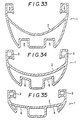
- the warm air path (comprising the warm air duct and the guiding groove) shares at least a part of the wall thereof with at least a part of the wall contacting the level surface of a sink water in the toilet bowl.
- the warm air passing through the warm air path can heat the trap water at the level surface thereof, thereby preventing the trap water from freezing, particularly in a cold district.
- the freezing of the trap water begins from the surface thereof. Therefore, the freezing of the trap water may be avoided by heating the water around the level surface thereof in the toilet bowl in the water closet according to this embodiment.
- Figs. 37 and 38 illustrate a first embodiment of the water closet for preventing the trap water from freezing.
- the water closet 1 shown in Figs. 37 and 38 is a bench type closet, and attached to the wall of the toilet room or the like at the rear side 1a.
- the referential numerals in Figs. 37 and 38 have the same meanings as given in Fig. 1 and the like.
- the warm air duct 4 shares the wall thereof with that of the toilet bowl 2 on the right and left sides thereof, whereby the warm air passing through the warm air duct 4 directly heat the toilet bowl 2, particularly around the level surface L of the trap water W. Therefore, the freezing of the trap water may be avoided.
- Figs. 39 and 40 illustrate another embodiment of the water closet for preventing the trap water from freezing.
- the warm air path in the bench type water closet 1 of this embodiment comprises the warm air duct 4 and the guiding groove 8.
- the guiding groove 8 shares the upper wall 8b thereof with the bottom wall of the toilet bowl 2, whereby the warm air in the guiding groove 8 directly contacts the bowl surface opposite to the trap water W around the level L.
- Figs. 25 to 40 the number of the warm air outlet, the direction of blowing the warm air out or the like may be different from those shown in Figs. 25 to 40.
- the warm air path may have, for example, the sectional profile as shown in Fig. 40.
- the water closet may be not only the bench type, but also the stool type or the like.
- the present invention also relates to a water closet unit containing an adapter which can attach the sitting type water closet having the warm air path to the wall of the toilet room.
- the water closet unit according to the present invention may blow the warm air out from the front portion thereof, thereby heating the leg of the user. Since the heating is effected with the warm air, the clothes are not burnt.
- the bench type water closet is attached to the wall of the toilet room with the adapter, and thus, the fixing strength may be extremely improved, even if the wall of the toilet room is made of a material having a weak strength, such as a wooden plate.
- Figs. 41 to 44 schematically illustrate the water closet unit according to the present invention.
- the sitting type water closet 1 is a bench type one, and attached at the rear side 1a thereof to the adapter 49 installed in the wall portion of the toilet room 20.
- the rim water conduit 3 is disposed around the upper portion of the toilet bowl 2 (Fig 42).
- the warm air duct 4 composing the warm air path 14 is longitudinally disposed at the side portion thereof, formed integrally with the toilet bowl.
- the end of the warm air duct 4 is an opening, i.e., the outlet 5, at the tip of the water closet 1.
- the rear end of the warm air duct 4 is an opening at the rear side 1a of the water closet 1.
- the water closet 1 has the trap 6 and the drainge hole 7.
- a toilet seat 22 and a toilet cover 23 are disposed on the upper portion of the water closet 1 in a manner that the closet can be opened and closed with the seat and the cover.
- the toilet seat 22 and the toilet cover 23 are rotatably fixed with a hinge shaft 25 to a case 24 mounted on the upper rear portion of the water closet 1.
- the bottom surface of the toilet seat 22 has rubber protuberances 26.
- the hinge shaft 25 may be moved up and down with a slight stroke.
- a seat switch 27 includig a pressure-sensitive switching mechanism may be disposed between the upper surface of the toilet bowl 2 and the hinge shaft 25.
- the seat switch 27 is connected via a lead wire 28 to a controller 29 installed in the wall 21 of the adapter or the toilet room.
- the controller 29 is connected through a signal wire 30 to the warm air generator 12.
- the outlet 32 of the generator 12 is cannected to the warm air duct 4.
- the seat switch 27 is turned on, the warm air generator 12 is actuated, and then, the warm air is blown out from the outlet 5.
- the warm air contacts and heats the lower half, particularly the calf, of the user. Because the warm air is blown out shortly after the actuation of the warm air generator 12, the water closet has a good starting performance, and thus provides a comfortable heating.
- the on-off control of the warm air generator may be carried out, using means other than the seat switch.
- Fig. 45 there are four pillars 41, 42, 43, 44 at four corners in the toilet room 20. Sleepers 45 and foundations 46 are arranged between the pillars, and the foundations 46 are arranged on pedestals 47 (Figs. 45 and 46).
- Metallic fixtures 48a having an L-letter shaped sectional profile are fastened with screws to the side walls of the spleepers 45 and foundations 46.
- a waterproof pan 48 is held on the metellic fixture 48a and composes a floor of the toilet room 20.
- the adapter 49 comprising a box-like structural frame.
- the frame type adapter 49 comprises twelve main angle bars 50 corresponding to twelve edges of a rectangular parallelepiped, and sub-angle bars 51 spanning the main angle bars 50.
- Plural bolt holes 52 are vertically provided in the sub-angle bars 51a facing the toilet room.
- the bench type water closet 1 is attached to the adapter 49 with bolts 53 through the bolt holes 52.
- the water closet 1 is fastened to the adapter 49 via a fixing plate 54 made of an iron plate.
- the fixing plate 54 has openings 55 for bolts 53, an opening 57 for a drainage pipe 56, and an opening 58 for the warm air outlet 32.
- the drainage pipe56 has a widened portion 56a at the end thereof.
- the widened portion 56a is connected via a gasket 59 to the drainage hole 7 of the water closet 1. Further, the widened portion 56a is held on the edge of the opening 57 of the fixing plate 54 via a packing 60.
- the drainage pipe 56 is an elbow pipe, and is connected with a wastepipe 61 at the other end.
- the bolts 53 are inserted through the bolt holes 64 of the water closet 1 via space nuts 62 and rubber packings 63, and then threadedly engaged with decorative nuts 67 through sectional nylon packings 65 and washers 66.
- openings 68 are provided through which the decorative nuts 67 may be clamped with a tool.
- a cover 69 is removably fitted over the opening 68 (Fig 41).
- Fig. 46 shows a bay window unit 72 which is attached to the outside of the pillars 41 and 42 and covers the adapter 49, and further a tank 73 for washing water installed in the adapter.
- a lidded waste trap 48b provided to the waterproof pan 48 is also shown.
- Appropriate decorative panel (not shown) or the like is disposed in the front face of the adapter 49.
- Fig. 48 two outlets 32 are symmetrically disposed to the warm air generator 12.
- the wearm air duct 4 is connected with the outlet 32 to communicate the warm air generator 12 and the water closet 1.
- the warm air generator 12 has L-shaped brackets 75 for attaching to the fixing plate 54 with screws (Figs. 46 and 47).
- the water closet 1 is fastened to the box-like and flame type adapter 49, and in turn the adapter 49 is attached to the pillars 41 and 42.
- the supporting strength of the water closet is extremely high. Because the bench type water closet is used, the floor (the waterproof pan 48) of the toilet room can be wholly washed. The washing water may be removed through the trap 48b.
- plural bolt holes 52 are provided in the sub-angle bars at various heights, with respect to one bolt hole 64 in the water closet 1.
- the height of the water closet 1 may be easily adjusted by changing the bolt hole in the sub-angle bars 51 through which the bolts 53 are inserted.
- the adapter 49 may be installed with protruding from the toilet room , or the bay window unit 72 may be installed, whereby the space of the toilet room may be enlarged.
- Fig. 49 illustrates another embodiment wherein the water closet 1 according to the present inveniton is installed in a different manner.
- a major part of the adapter 49 is installed in the inside of the pillars 41 and 42.
- the main angle bar 50 in the lower front part of the adapter 49 is fixed on the sleeper 45.
- the referential numerals in Fig. 49 have the meanings same as those given in Fig. 41.
- the water closet used includes the bench type, and the water closet fixed on the floor and the adapter.
- a device for controlling an amount of the warm air may be installed.
- the adapter used includes not only the frame type, but also a box which is made of plates and has appropriate openings.
- the shape of the adapter may be appropriately adjusted in accordance with the shape of the toilet room.
- the water closet of the present invention may be adjusted so as to attach the same to the wall or the like of the toilet room, instead of the pillars.
- the sitting type water closet can be installed in the toilet room with an extremely high strength, using the water closet unit of the present invention.
- An air conditioner or the tank for the washing water may be installed within the adapter. By protruding the adapter from the building as the bay window, the inner space may be enlarged.
- Figs. 1 to 24 illustrate various embodiments of the water closets which may be employed in the water closet unit according to the present invention.
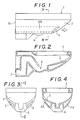
- Figs. 1 to 4 show a first embodiment of the water closet which may be used in the water closet unit of the present invention.
- the western-style bench type water closet 1 is attached to the side wall of the toilet room or the like at the rear side 1a of the closet.
- a toilet bowl 2 is provided to the front portion of the closet 1
- a rim water conduit 3 is provided to the upper portion of the bowl 2, surrounding the bowl 2.
- the warm air duct 4A is disposed integrally with the bowl 2, extending longitudinally, i. e., from the rear portion of the bowl to the front portion of the bowl.
- the warm air duct 4A is ended at the front portion of the bowl 2 to form a warm air outlet 5.
- the other end of the warm air duct 4A is open at the rear side 1a of the water closet 1.
- the water closet 1 further contains a trap 6 and a drainage hole 7.
- the water closet having the above structure can blow the warm air out from the outlet 5, by disposing a warm air generator (refer to Fig. 25, ect.) connected with the warm air duct 4A.
- a warm air generator (refer to Fig. 25, ect.) connected with the warm air duct 4A.
- Figs. 5 and 6 show another embodiment of the water closet which may be used in the water closet unit of the present invention.
- the outlet 5 is disposed at the position higher than that of the above embodiment shown in Figs. 1 to 4.
- the warm air duct 4A is also disposed at the front portion of the bowl 2, diagonally upwardly extending from the rear portion to the front portion. Therefore, the warm air is blown out diagonally upwardly, and thus, the upper part in the leg of the user is heated.
- Figs. 7 to 10 show other embodiment of the water closet which may be employed in the water closet unit of the present invention.
- the warm air duct 4A is disposed along the upper periphery of the bowl 2.
- the warm air duct 4A surrounds the outer periphery of the rim water conduit 3, at the front portion of the toilet bowl 2.
- the outlet 5 is formed in the form of opening disposed in the bottom wall of the warm air duct 4A at the front portion of the bowl 2.
- three outlets are disposed, although any number of the outlets 5 may be formed.
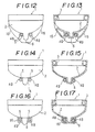
- Figs. 11 to 13 illustrate other embodiment of the water closet which may be used in the water closet unit of the present invention.
- the warm air duct 4B formed separately from the bowl 2 is disposed along the bottom surface of the bowl 2, extending longitudinally, i. e., from the rear portion of the bowl to the front portion of the bowl.
- the outlet 5 is formed at the end of the duct 4B.
- a cover 15 for the bowl 2 is arranged.
- the duct 4B is disposed in a space between the cover 15 and trap 6 .
- Figs. 14 and 15 show other embodiment of the water closet which may be used in the water closet unit of the present invention. This embodiment is different from the above embodiment with respect to the fact that the cover for the bowl 2 is not provided, and thus, the warm air duct 4B is exposed.
- the warm air duct 4B can be attached to the water closet without changing the conventional shape of the closet per se.
- the water closet can be easily manufactured.
- Figs. 16 and 17 show other embodiment of the water closet which may be employed in the water closet unit of the present invention.
- the water closet 1 of this embodiment corresponds to the water closet wherein the cover 16 for the warm air duct is arranged in the water closet of the embodiment as shown in Figs. 14 and 15.
- the cover 16 can be attached with, for example, an adhesive.
- the water closet of the embodiment as shown in Figs. 16 and 17 can also be easily manufactured without changing the conventional shape of the water closet. Further, the cover 16 brings about a good appearance.
- Figs. 18 and 19 illustrate other embodiment of the water closet which may be used in the water closet unit of the present invention.
- a wall 17 is arranged to form the warm air duct 4A with the bowl cover 15, trap 6, the bottom surface of the bowl 2 and the wall 17.
- Figs. 20 and 21 show other embodiment of the water closet which may be used in the water closet unit of the present invention.
- the warm air duct 4B is attached to the water closet 1 with a rubber sucker 18.
- the duct 4B can be easily attached to and removed from the closet 1.
- Figs. 22 to 24 show other embodiment of the water closet which may be used in the water closet unit of the present invention.
- the warm air duct 4A formed integrally with the water closet 1 is disposed, longitudinally extending to the lower portion of the bowl.
- a warm air guiding groove 8 which does not have a bottom wall is disposed, extending to the tip of the bowl so as to guide the warm air toward the upper portion of the leg of the user.
- the outlet at the end of the warm air duct is disposed backwardly in a given distance from the tip of the bowl. Therefore, if the foul water runs down to the outlet, the foul water is prevented from entering into the warm air duct. Thus, it may be avoided that the foul water becomes a source of a malodor. Even if the dried foul water is bonded to the ceiling or the side wall in the warm air duct, it may be easily removed by wiping.
- the warm air duct may be formed integrally with the toilet bowl.
- the duct may be formed separately from the bowl, and then attached thereto.
- a means for facilitating the attachment of the water closet to the adaper is provided.
- the fixing plate is attached on the adapter side facing the toilet room, and nuts are fixed on the plate, whereby the water closet can be fastened to the adapter with the bolts threadedly fittable to the nuts.
- the bolts are fixed on the plate instead of the nuts, and the bolts are inserted through the bolts holes in the water closet, whereby the water closet can be fastened to the adapter with the nuts threadedly fittable to the bolts. Because the fixing plate having such structures is attached to the adapter, the water closet can be attached to the adapter by bringing the rear side of the water closet with the fixing plate and then fastening the bolts or nuts.
- a register of the water closet and the fixing plate can be easily carried out, and the bolts and nuts can be easily fastened.
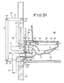
- Figs. 50 to 52 schematically show the condition wherein the water closet 1 is attached to the adapter 49, using the fixing plate having such specific structure, particularly the fixing plate 54 shown in Fig. 53.
- the fixing plate 54 has through holes 163 for the bolts 162 to attach the water closet 1.
- through holes 164 are provided for the bolts 162.
- Nuts 165 threadedly fittable to the bolts 162 are fixed by welding or the like at the positions of the through holes 163 on the rear surface of the fixing plate 54 (Fig. 53).
- the fixing plate 54 has a through hole 166 for a bolt 31a to attach the warm air generator 12.
- the fixing plate 54 is covered with a decorative panel 167.
- the panel 167 includes a through hole 167a for the drainage pipe 56, a through hole 167b for the warm air outlet 32, through holes 167c for the bolts 31a, through holes 167d for the bolts 162, or the like.
- the warm air generator 12 has an L-shaped bracket 75 so as to attach the generator to the fixing plate 54 with screws (Fig. 52).
- the warm air generator 12 and the decorative panel 167 are attached by inserting the bolts 31a through the holes 167c and 166 in the decorative panel 167 and the fixing plate 54, and fastening the nuts.
- the fixing plate 54 is fixed to the adapter 49 with the bolts 53.
- the warm air generator 12 and the decorative panel 167 are then fixed with the bolts 31a.
- the rear end 1a of the water closet 1 is brought into contact with the decorative panel 167, and the bolts 162 are threadedly engaged with the nuts 165.
- the bolts 162 can be easily engaged with the nuts 165, which have been fastened on the back surface of the fixing plate 54.
- Fig. 54 shows another fixing plate 54′ which may be used in the present invention.
- the fixing plate 54′ does not have bolt holes 163 and nuts 165. Instead thereof, stud bolts 74 are provided on the fixing plate 54′.
- the water closet 1 can be attached by inserting the stud bolts 74 through the bolt holes 167d in the decorative panel 167 and the bolt holes 164 in the water closet 1, and then fastening the nuts.
- the referential numerals in Fig. 54 have the same meanings as given in Fig. 53.
- the water closet 1 can be easily attached to the adapter, using also the fixing plate 54′.
- the warm air outlet may be arranged on the side wall of the adapter, instead of or in addition to the warm air outlet in the water closet.
- the warm air outlet is provided on the side wall same as that for attaching the water closet. Further, the warm air outlet is provided at a height lower than that of the top of the water closet.
- the warm air is blown out from the lower portion of the wall behind the water closet and can rapidly heat the leg of the user. Further, the toilet room is wholly heated, too.
- the warm air outlets are arranged in both of the side wall of the adapter and the lower portion of the water closet, the warm air is also blown out from the water closet, and thus, the leg of the user may be effectively heated. Further, the dew condensation of the toilet bowl and the freezing of the trap water can be avoided.
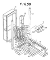
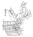
- Figs. 55 to 59 illustrate the condition wherein the adapter 49 carrying the water closet 1 fastened thereto is attached to the pillar 41 in the toilet room 20.
- the adapter 49 contains the warm air generator 12 therein.
- the referential numerals in Figs. 55 to 59 have the meanings as given above.
- the toilet room 20 has a door 269 (Fig. 56).
- the adapter 49 carries appropriate decorative panels 49A, 49B and 49C on the front and upper sides thereof (Fig. 57).
- the warm air generator 12 is included in a casing 284 which is transversely arranged behind the water closet 1.
- the casing 284 further contains a turbo-fan, a resistance heating element (such as a ceramic heater element) and the like.
- the warm air generator 12 has the warm air pipes 282 and the warm air outlets 286 on both sides at a height lower than that of the upper face IU of the water closet.
- the warm air generator 12 has an intake vent 288.
- openings 290 are arranged on the front panel 49B of the adapter 49 so that the outlets 286 face the toilet room 20.
- the warm air is blown out from the outlets 286 arranged on the wall of the adapter and the outlets 5 in the water closet 1, to effect the heating and, particularly the heating of the leg of the user.
- the warm air generator having the resistance heating element as a heat source is employed, the warm air with a high temperature is blown out shortly after the warm air generator is turned on, and thus, the water closet has a good starting performance.
- the warm air outlet on the wall of the adapter may be arranged at a height lower than that of the water closet, whereby the leg of the user may be heated more sufficiently.
- the outlets 286 on the wall of the adapter are arranged in both sides of the water closet as in the embodiment illustrated in Figs. 57 to 60, the toilet room 20 may be more effectively heated as a whole.
- a device for controlling that the warm air is blown out from either the outlet 286 on the wall or the outlet 5 in the water closet may be constructed so that the whole heating is effected by blowing the warm air out only from the outlet 286, and further, the warm air is blown out from the outlet 5 when the water closet is employed.
- the water closet and the water closet unit according to the present invention may be controlled in various manners by employing the seat switch.
- an on-off control of the warm air generator may be carried out by an on-off signal by the seat switch.
- the warm air starts to blow, and when the user stands up from the seat, the blowing-off ceases. Therefore, the electric power consumed may be saved, and this embodiment is economical.
- a timer may be added to the warm air generator, and at the same time, the power of the warm air generator may be made controllable.
- the warm air generator when the timer is on, The warm air generator is operated under a low power to blow the warm air having a relatively low temperature.
- the warm air generator When the user sits down on the toilet seat, the warm air generator is operated under a high power to blow the warm air having a relatively high temperature during the employment of the water closet by the user.
- the temperature in the whole toilet room may be elevated by blowing the warm air out when the water closet is not used.
- the warm air generator is operated under a high power when the timer is on, and the low power is utilized if the user feels the air hot.
- the seat switch 27 including the pressure-sensitive switch mechanism is disposed between the hinge shaft 25 and the upper surface of the toilet bowl 2.
- the seat switch 27 is connected via the lead wire 28 with the controller 29, and then via the signal wire 30 with the warm air generator 12.
- the outlet 32 of the warm air generator 12 is communicated with the warm air duct 4.
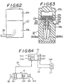
- Figs. 61 to 63 illustrate the structure of the seat switch 27.
- the seat switch 27 is covered with cylindrical jackets 27a, 27b made of an elastic material, such as a rubber.
- a pair of semicircular electrodes 27c, 27d is disposed by introducing into receptacles 27C, 27D in the elastic jacket 27a.
- the end of each receptacle 27C and 27D is connected with lead wires 28 (28a and 28b).
- An insulating material 27e is introduced between the electrodes 27c and 27d.
- an electrically conductive, elastic (e.g., rubber) piece 28g and a press piece 27h are stacked.
- the cap-shaped elastic jacket 27b is deformed as press-collapsed in an axial direction.
- the conductive elastic piece 27g is pressed with the press piece 27h.
- the conductive elastic piece 27g is deformed so that a part thereof is introduced into the opening of the insulating spacer 27f.
- the tip of the introduced part of the conductive elastic piece 27g contacts the electrodes 27c, 27d, whereby the electrodes 27c and 27d are connected with each other, and the seat switch is turned on.
- the elastic jacket 27b recovers the original shape thereof.
- the conductive elastic piece 27g recovers the original shape, and then separates from the electrodes 27c and 27d. Therefore, the electrodes 27c and 27d separate from each other, and the seat switch 27 is turned off.
- the seat switch 27 is turned on, the warm air generator 12 is then operated, and the warm air is blown out from the outlet 5.
- the warm air contacts the lower half of the body, particularly the calf, of the user, thereby heating the leg of the user.
- the warm air generator 12 has an electric heater (ceramic heater) 381 as a heat source.
- the generator further contains a propeller fan 382 as a fan.
- An air filter 383a is disposed to an intake vent 383.
- the warm air generator 12 is installed within the bay window unit 72.
- the controller 29 comprises a main switch 384 for turning the whole circuit on or off, a temperature presetting device 385 for setting a standard temperature at which the electric heat 381 is operated, the timer 386, a switch 387 for forcing the warm air generator 12 to work, and the like.
- the lead wire 28 from the seat switch 27 and the signal wire 30 to the warm air generator 12 are connected with the controller 29.
- a temperature sensor 388 to detect the temperature in the toilet room 20 is connected with the controller 29.
- the controller 29 contains a device for the control as described below, such as a sequence control circuit of microcomputer.
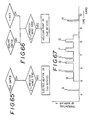
- the temperature in the toilet room 20 is judged if it is lower than the predetermined standard temperature (e.g., 20°C). If the temperature is lower than the predetermined one, the electric heater 381 is turned on, the propeller fan 382 is rotated, and then the warm air is blown out from the outlet 5. If the temperature is higher than the predetermined one, the warm air is not blown out.
- the electric heater 381 is turned off and the rotation of the propeller fan 382 is stopped.
- the temperature in the toilet room 20 is judged if it is lower than the predetermined one. If the temperature is lower, the electric heater 381 is turned on, and the propeller fan 382 is rotated, and thus, the warm air is blown out.
- Fig. 67 shows an embodiment wherein the timer 386 is employed.
- the timer 386 is presetted so that it is turned on only during 5:00 a.m. to 8:30 a.m., when the water closet is frequently employed.
- the toilet room 20 is intended to heat as a whole (arrow B).
- the electric heater 381 is operated in a full power to blow the warm air out (arrows C, D, E, F, G).
- the electric heater 381 is worked to blow the warm air as shown in arrows A and H in Fig. 67.
- the electric heater which can save electricity (for example, the resistance heating element which can change the powers, for example, of 400W and 800W) and to blow the warm air having relatively low temperature by working the electric heater under a lower power when the timer is on (arrow B in Fig. 67).
- the power of the heater may be changed between more than two levels, or continuously controlled.
- the seat switch brings about another control system.
- the present invention also provides a water closet or a water closet unit comprising the warm air path [(i) the warm air duct and optionally (ii) the warm air guiding groove] for blowing the warm air out to the leg of the user from the lower portion of the water closet installed to the toilet room, the warm air generator [(i) the blower arranged in the warm air duct, for generating the air stream flowing to the leg of the user, and (ii) the electric heater arranged in the warm air duct, for heating the air stream flowing through the duct, when turned on], and a controlling device which applies an electric current to the electric heater when the user of the water closet sits down on the toilet seat, but restrains an amount of the air from the blower until a given period of time elapses.
- the electric heater is turned on, when the user sits down on the water closet installed in the toilet room. Further, the amount of the air from the blower is restrained, until the given period of time elapses after the user sits down on the water closet. Therefore, the heat radiation from the electric heater is prevented, and thus, the heater can rapidly go up to the predetermined temperature. After the given period of time elapses, the blower starts to work for conveying a given amount of the warm air. Then, the warm air heated up to the predetermined temperature is blown out from the outlet of the warm air duct disposed in the lower portion of the sitting type water closet to the leg of the user. Therefore, this embodiment can prevent a clod air from blowing out, and a cool touch to the user can be avoided, shortly after the electric heater starts to work.
- Figs. 68 to 70 illustrate the toilet room including the water closet unit of the above embodiment.
- Figs. 71 and 72 show a leg heater contained in the warm air generator.
- the water closet unit 401 comprises a heat pump type air-conditioner 403 for wholly heating the toilet room 20; a ventilating duct 404 for blowing the warm air out into the toilet room 20; the blower 452 arranged in the warm air duct 404 for generating the air stream to the leg of the user; and the leg heater 405 for heating the air passing through the ventilating duct 404.
- the water closet unit 401 is connected with the control panel 406.
- the toilet room 20 comprises a side wall 422 carrying the door 269; a side wall 424 carrying a container cabinet 423 for toilet paper; a side wall 425 carrying the control panel 406; the bay window unit 72 protruding outwardly; a resin floor 48; and a ceiling 429 carrying an air fan.
- the bay window unit 72 comprises a side wall 426a, and a counter 426c which is arranged in the front wall 426b and contains the air-conditioner 403 and the leg heater 405 therein.
- the air-conditioner 403 is a window fan type, and fastened on the rear face of the side wall 426d of the counter 426c.
- the air-conditioner 403 is contained in the adapter 49 comprising the counter 426c and the side wall 426b.
- the air-conditioner 403 may contain a refrigeration cycle (not shown) within a unit case 431. Grilles 432 are provided to the outlet arranged on the front wall of the unit case 431, and an intake vent (not shown) and an outlet (not shown) arranged on the side wall of the unit case 431.
- the ventilating duct 404 comprises an intake duct 441 for inhaling the air present in the toilet room 20; a heater duct 442 connecting with the intake duct 441; and two warm air ducts 4 formed integrally on the lower portion of the toilet bowl 2 and connected with the heater duct 442.
- the intake duct 441 has an intake vent 444 which faces the toilet room 20 to inhale the air present therein, and is arranged at the back of the grill 432 of the air-conditioner 403.
- the heater duct 442 is disposed to the leg heater 405.
- the warm air duct 4 has the warm air outlet 5 which has an opening near to the leg of the user, and blows the warm air out to the leg exposed when the user employs the water closet. From the warm air outlet 5 to the tip of the water closet 1, there is provided the warm air guiding groove 8 so as to minimize the reduction of the temperature of the warm air.
- the leg heater 405 comprises a casing 451 for heat insulating the heater duct 442 from the air; an axial flow fan or the blower 452, which is arranged in the heater duct 442 and generates, in the heater duct 442, the air stream to the toilet room 20; two harmonica type positive thermistor cells (hereinafter referred to as PTC heater) 453 which are arranged in the heater duct 442, and heat the air passing therethrough.
- PTC heater two harmonica type positive thermistor cells
- the casing 451 has a parallelepipedic shape, and is fastened to the rear side of the side wall 426b of the counter 426c, with the fixing stays 451a welded to the casing 451.
- the casing 451 carries, on a side plate 451b, a connector 454 for applying the electric current to the axial flow fan 452 and the PTC heater 453. Further, on the casing 451, a tail end 442a of the side plate 451b, and a two-way tail end 442b of the heater duct 442 is outwardly protruded from the other side plate 451c.
- the axial flow fan 452 can serve to blow out a given amount of the air from the warm air outlet 5 to the exposed leg of the user, when received a given amount of electric current from the control circuit 466.
- the axial flow fan 452 receives electric current from the control circuit 466 in an amount less than the predetermined one, the fan serves to blow the air to the exposed leg of the user in an amount less than the predetermined one.
- the PTC heater 453 is formed by arranging many positive thermistor cell plates 455 [comprising conductive ceramics mainly composed of barium titanate (BaTiO3), or the like] between a positive electrode plate 456 and a negative electrode plate 457.
- the PTC heater is formed so that the resistance thereof is suddenly increased at a given Curie point, by introducing various additives.
- the PTC heater 453 makes use of the PTC characteristic property to maintain the surface temperature at a constant level by a current restriction function in the area where the resistance is suddenly changed.
- the Curie point of the PTC heater 453 is set to the temperature (e.g., 300°C) lower than an ignition point (e.g., 400°C) of dust or the like so that the surface temperature (almost the same temperature as Curie point) of the PTC heater 453 is set to the temperature lower than the ignition temperature of the dust.
- Fig. 73 shows a block diagram of the built-in control circuit of the control panel.
- the control panel 406 carries, on the entire front surface thereof, a switch 461 of the leg heater, a switch 462 of the air-conditioner, and a switch 463 for changing an air-cooling and an air-heating.
- the control panel 406 contains a control circuit 466 as a controlling device to receive signals from the leg heater switch 461, the air-conditioner switch 462, the cooling/heating-changing switch 463, the seat switch 27 and timer 465.
- the leg heater switch 461 is a manual switch which gives to the control circuit 466 on-off signals of the leg heater 405, i.e., the axial flow fan 452 and the PTC heater 453.
- the leg heater switch 461 has three positions, i.e., "off”, “weak”, and “strong”.
- the "weak” means on of the PTC heaters 453 is on, and the “strong” means two PTC heaters 453 are on.
- the air-conditioner switch 462 is a manual switch which gives to the control circuit 466 on-off signals of the air-conditioner 403.
- the cooling-heating changing switch 463 is a manual switch for changing the air-cooling to the air-heating, and vice versa.
- the seat switch 27 is disposed under the toilet seat 22 of the water closet 1. When the seat switch 27 detects that the user sits down on the water closet 1, the seat switch 27 sends a sitting signal to the timer 465 and the control circuit 466 so that the axial flow fan 452 and the PTC heater are turned on.
- the seat switch 27 contains a pressure-sensitive switch which changes the resistance thereof by the weight of the user who sits down on the water closet 1, and sends the on-signal to the timer 465 and the control circuit 466 so that the leg heater 405 is turned on.
- the timer 465 when receiving the on-signal from the seat switch 27, gives an off-signal to the control circuit 466 so as to defer operating the axial flow fan 452 for a given period of time (for example, for 5 seconds).
- the control circuit 466 performs, in accordance with the input signals received, the on-off control of the air-conditioner 403, the axial flow fan 452 and the PTC heater 453, via an electrical box 467. Further, the control circuit 466 turns the axial flow fan 452 off to restrain the amount of the air from the fan 452, during a period of time when the circuit 466 receives the off-signal of the fan 452 from the timer 465.
- the electrical box 467 is arranged in the upper portion of the unit case 431 of the air-conditioner 403, connected with a domestic electric source (100 V), and supplies an electric current to the air conditioner 403, the axial flow fan 452 and the PTC heater 453.
- a domestic electric source 100 V
- leg heater 405 in the control circuit 466 The operation of the leg heater 405 in the control circuit 466 according to the above embodiment will be explained, referring to Fig. 74.
- step S1 a judgement is made if the leg heater switch 461 is on (or strong or weak) or off (step S1).
- the leg heater switch 461 is off (No)
- the PTC heater 453 is turned off (step S2)
- the axial flow fan 452 is turned off (step S3). Thereafter, the step S1 is repeated.
- step S1 When the leg heater switch 461 is on (Yes) in the step S1, a judgement is made if the seat switch 27 is on (step S4). When the seat switch 27 is off (No), the step S2 is selected.
- the seat switch 27 sends the on-signal for turning the leg heater 405 on to the timer 465 and the control circuit 466.
- step S5 when the seat switch 27 is turned on (Yes), the PTC heater is turned on (step S5), and the axial flow fan 452 is turned off (step S6).
- the PTC heater 453 has a large hear capacity, and thus, can not be rapidly elevated to the predetermined temperature. If the PTC heater 453 in this condition is brought into contact with a fresh air (not heated) by the axial flow fan 452, the time necessary to elevate the temperature of the heater 453 per se to the predetermined one becomes longer. As a result, the air having a relatively low temperature is blown out from the warm air outlet 5 to the leg of the user.
- the undressed user would feel the touch cooler than that the user feels when dressed.
- the user sitting on the seat 22 can not but receive the cool air at the leg. Therefore, it is necessary to introduce a means for avoiding the cool touch from the user, in the water closet 1 carrying the leg heater 405 and the warm air outlet 5 therefor on the lower portion of the closet.
- the axial flow fan 452 is maintained to be off, until a given period on time (e.g., 5 seconds) elapses after the seat switch is turned on (step S7), to restrain the amount of the air blown.
- the PTC heater 453 stands under the windless condition, and the heat radiation therefrom is prevented, whereby the heater is rapidly elevated to the predetermined temperature.
- the axial flow fan 452 is turned on to produce the air stream in the ventilating duct 404 (step S8).
- the air present in the toilet room 20 is sucked into the intake duct 441 from the intake vent.
- the air sucked into the intake duct 441 is introduced into the heater duct 442, heated to the predetermined temperature with the PTC heater 453, and then conveyed to the warm air duct 4.
- the warm air introduced into the warm air duct 4 is blown out from the outlet 5, blows along the guiding groove 8, on the closet, and reaches the leg of the user, thereby sufficiently heating the user.
- Table 1 Time after turning seat switch on (sec.) Turning fan and PTC heater on Deferring fan 5 sec., but turning heater on 0-15 cool touch no feeling 15-20 no feeling no feeling ⁇ 20 warm touch warm touch (Temperature of toilet room 20 is 3°C)
- Fig. 75 shows the flow chart of another operation of the leg heater 405 in the control circuit 466. The explanation of the operations described with reference to Fig. 74 will be omitted.
- step S9 not only the PTC heater 453, but also the axial flow fan 452 are turned on at the same time until the predetermined period of time elapses, but the fan is operated under the condition to flow a small amount of the air out, namely, the air in an amount smaller than the predetermined normal amount (step S9).
- small amount of the air or the like used herein means the amount which does not give the user the cool touch.
- the frame type adapter may also be used.
- an electric heater such as a nichrome wire heater may also be employed.
- Fig.76 is a graph showing the relationship between the surface temperature of the PTC heater and a ratio of resistane at a given temperature to that at 25°C (R25).
- the PTC characteristics are changed, and the PTC resistance curve is changed to the curve I to the curve II.
- the operation point which is the intersection point of a wind velocity v (m/s) and the PTC resistance curve is moved from the point A to the point B.
- the surface temperature of the PTC heater is elevated by T°C.
- the conventional heating apparatus for the toilet room which apparatus employs the PTC heater has a problem that the PTC heater encounters the reduction deterioration when used for a long time, and then the PTC properties are changed. As a result, the surface temperature of the PTC heater, and thus, the temperature of the toilet room is elevated, whereby the heating feeling is lowered.
- the present invention provides a combination of an outside air introducing type ventilating duct which inhales the air present outside the toilet room and blows out into the toilet room, a blower which is arranged in the ventilating duct and produces the air stream into the toilet room, and the PTC heater which is arranged in the ventilating duct and heats the air.
- the above structure brings about the following advantages.
- the air present outside the toilet room is blown out into the toilet room by the blower, and thus the PTC heater is not exposed with the reducing gas such as hydrogen sulfide present in the toilet room, whereby the elevation of the surface temperature of the positive thermistor caused by the reduction deterioration can be avoided.
- the PTC heater can maintain the surface temperature thereof in a constant level. Therefore, when the temperature of the air outside the toilet room is lowered, the difference between the surface temperature of the PTC heater and that of the outside air is increased, and thus the heat release value is increased. Thus, the heated air blown out into the toilet room has a constant temperature, independently of the variation of the outside temperature. Further, the heating feeling is not lowered, even if the outside air has a low temperature.
- Fig. 77 shows an embodiment wherein the above water closet is installed.
- the water closet unit 501 is arranged within the counter 523 disposed on the side wall 522 which is protruded to the outside 521 of the toilet room 20.
- the water closet 1 is attached to the side wall 423a of the counter 523.
- the counter 523 and the side wall 423a form the adapter.
- the water closet 501 comprises the outside air introducing type ventilating duct 503 for blowing out the air (referred to as outside air) present outside 521 of the toilet room 20 (e.g., the outsides, or the adjoining room), and the warm air generator 12 arranged within the ventilating duct 503 comprises a bellows duct 531 for introducing the outside air, a chamber 532 connected with the duct 531, a bellows duct 533 connected with the chamber 532, the warm air duct 534 connected with the duct 533, and two warm air ducts 4 which are diverged from the warm air duct 534 and blow the warm air out to the leg of the user.
- outside air air present outside 521 of the toilet room 20
- the warm air generator 12 arranged within the ventilating duct 503 comprises a bellows duct 531 for introducing the outside air, a chamber 532 connected with the duct 531, a bellows duct 533 connected with the chamber 532, the warm air duct 534 connected with the
- An intake vent 531b having a hood 531a is arranged to the tip of the duct 531.
- the chamber 532 forms a space having a sectional area larger than those of the ducts 531 and 533, so as to reduce the pressure and control the variation caused by the wind as to the amount of the inhaled air.
- a filter 532a is disposed to adsorb the dust included in the outside air.
- Heat insulating materials are disposed to the bifurcated ends 534c of the ventilating duct 534. Between the bifurcated ends 534c of the ventilating duct 534 and the warm air duct 4, there are provided sealing materials 534a and 534b to leak the warm air. At the end of the warm air duct 4, there is an opening between the lower portion of the water closet 1 and the floor 48 to form the warm air duct 4.
- the warm air generator 12 comprises the casing 451 which covers the ventilating duct 534 with a gap therebetween to assure insulation with the air, the blower or the axial flow fan 452 which is arranged within the ventilating duct 534 and generates the air stream to the inside 425 of the toilet room 20, and two PTC heaters which are arranged within the ventilating duct 534 and heats the air stream passing therethrough.
- the warm air generator and the like contained in the water closet unit 501 are turned on, when the pressure-sensitive seat switch 27 disposed under the toilet seat 22 of the water closet 1 is turned on.
- the resistance of the seat switch is changed by the weight of the user, and thus, the switch sends on-signals to the axial flow fan 452 and the PTC heater 453.
- the switch sends off-signals to the axial flow fan 452 and the PTC heater 453.
- the switch sends off-signals to the axial flow fan 452 and the PTC heater 453.
- the axial flow fan 452 is rotated upon the receipt of the on-signal, and the outside air present in the outside 521 of the toilet room 20 is sucked through the outside air intake vent 531b to the ventilating duct 503.
- the sucked air is introduced into the chamber 532 via the duct 531. Relatively large dusts contained in the outside air are caught by the filter 532a.
- the outside air After passing through the chamber 532, the outside air is conveyed to the ventilating duct 534 via the duct 322.
- the Curie point of the PTC heater 453 is presetted to the point below the ignition temperature of the duct contained in the outside air. Upon receiving the on-signal, the PTC heater 453 consumes a large amount of the electric current to generate the heat, when the outside air has the low temperature, namely the resistance of the PTC heater is low. If the surface temperature is elevated to the temperature above the presetted Curie point, the resistance is rapidly increased. Then, the amount of the current consumed is restrained, and a constant surface temperature may be maintained, whereby the surface temperature may be maintained under the ignition temperature of the duct.
- the air heated by the PTC heater 453 is the outside air which is introduced into ventilating duct 534 and is free from the reducing gases such as hydrogen sulfide, the reduction deterioration causing the elevation of the surface temperature of the PTC heater may be avoided, and thus, the ignition of foreign substances such as the dust adsorbed to the heater may be prevented.
- a reliable heating apparatus for the toilet room may be provided.
- the PTC heater 453 has a constant surface temperature.
- the surface temperature of the PTC heater 453 becomes largely different from the temperature of the outside air.
- the PTC heater may reduce the resistance thereof, consume a large amount of the current, and increase the heat (W) generated, whereby the reduction of the temperature of the outside air may be compensated by the increase of the heat generated. Therefore, the warm air outlet 5 of the warm air duct 4 can blow out the warm air heated by the PTC heater and having a constant temperature, regardless of the variation of the temperature of the outside air. Accordingly, the deterioration in the heating feeling can be prevented.
- the temperature drop of the warm air blown out from the warm air outlet (caused by the temperature drop of the outside air) can be more effectively prevented.
- the amount of the air blown out can be controlled in accordance with the outside air temperature determined through a sensor for detecting the temperature of the outside air. For example, when the temperature of the outside air is lowered, the amount of the air blown out may be reduced to thereby maintain a constant temperature of the warm air at the warm air outlet.
- the warm air outlet may be arranged on the side wall, ceiling, floor, or the like of the toilet room.
- the PTC heater may be formed by placing plural PTC heater plates by the side of another, the PTC heater may be produced from a single PTC heater.
- an open-off valve may be disposed to the warm air duct so as to open and close the duct, dependently upon the necessity of the heating.
- an air-conditioning apparatus such as an air-cooling apparatus, an air-cooling and heating apparatus, a ventilating apparatus may be installed in addition to the air-heating apparatus.
- the PTC heater exhibits a function to control the amount of the current at the area where the resistance is suddenly increased from the point corresponding to the Curie point.
- the PTC heater has the property that the temperature thereof is not elevated above a given temperature.
- the PTC heater does not require a protection device for overheating.
- the PTC heater employed in the heating apparatus can adsorb the dust from paper, clothes, or the like, which dust usually flies therein.
- the PTC heater employed in the heating apparatus for the toilet room is usually presetted to the temperature at which the dust from paper, clothes or the like does not ignite, by virtue of the function of controlling the current.
- the PTC heater When the PTC heater is reduced with the reducing substances, however, the resistance increase caused by the temperature elevation becomes smaller. In other words, the current controlling function is lost if the PTC heater is reduced.
- the PTC heater can abnormally generate the heat. If the PTC heater is overheated, the PTC heater can reach the temperature at which the dust from paper, clothes or the like can ignite.
- the PTC heater is overheated, the user can feel uncomfortable touch in the air overheated and blown out from the heating apparatus for the toilet room.
- the PTC heater is turned off by the safety means, if the PTC heater arranged in the ventilating duct is reduced with the reducing substances such as hydrogen sulfide, ammonia or the like contained in the air of the toilet room, thereby being rendered into the state where the resistance increase can not be obtained with the temperature elevation; and then, the PTC heater is overheated to the predetermined temperature which is the temperature near to the ignition point of the dust, such as paper, fiber from clothes, or which is the temperature giving the uncomfortable feeling to the user.
- the reducing substances such as hydrogen sulfide, ammonia or the like contained in the air of the toilet room
- Fig. 79 shows an example wherein the above embodiment is installed in the water closet unit.
- the water closet unit 601 has the ventilating duct 604 for conveying the air from the lower portion of the toilet bowl 2 in the water closet 1 to the leg of the user.
- the duct 606 with the box disposed in the air-conditioner box 605 or adapter arranged at the rear side of the water closet 1 is connected with two ducts 4 integrally formed with the water closet 1 (Fig. 70) through the ventilating duct 604.
- the duct 606 within the box comprises an intake duct 609 for inhaling the air in the toilet room 20, a bellows duct 610, and a heater unit 611.
- the intake duct 609 has a grill 432 in the upstream portion of the opening.
- a filter 613 is provided to prevent the paper or the fiber of the clothes from entering the heater unit 611.
- the bellows duct 610 is a duct for guiding the air sucked from the intake duct 609 to the heater unit 611.
- the blower 614 At the upstream portion of the heater unit 611, the blower 614 to generate in the ventilating duct 604 the air stream into the toilet room 20.
- This type of the blower 614 comprises the axial flow fan 451 disposed within the cylindrical resin blowing duct 615.
- a heat insulating duct 618 made of a heat insulating material follows the downstream portion of the blower 614.
- the insulating duct 618 contains therein a first PTC heater 619 and a second PTC heater.
- a heat insulating material 614 is interposed therebetween. The first PTC heater and the second PTC heater generate the heat when turned on, and the resistance thereof is suddenly increased from the Curie point.
- the Curie point is presetted, for example, to 220-250°C which is lower than about 350°C, i.e., the ignition temperature of the paper, fiber of clothes, or the like.
- the first or second PTC heater 619 or 620 is an assembled article manufactured by laminating plural PTC heater plates with gaps therebetween in the form of a harmonica. The heater is arranged so that the air passes through the gaps between the PTC heater plates.
- Fig. 80 shows an electrical circuit 624 for the on-off control of the first PTC heater 619 and the second PTC heater 620.
- the first PTC heater 619 and the second PTC heater 620 are connected with each other in parallel, and can be connected with a commercial alternating source 624, if the main switch 623 is manually turned on by the user.
- the second PTC heater has a sub-switch 625 which is connected with the second PTC heater in series and can manually turn only the second PTC heater 620 on and off.
- both of the first and second PTC heaters 619 and 620 are turned on, if the sub-switch 625 is turned on.
- only the first PTC heater 619 is turned on, if the sub-switch 625 is turned off.
- temperature fuses 626 and 627 are interposed in series. Temperature fuses 626 and 627 are the safety means in this embodiment. If an atmosphere temperature is elevated up to the predetermined value, fuses are melted to break the circuit of the first and second PTC heaters 619 and 620. As shown in Fig. 79, temperature fuses 626 and 627 are arranged in the insulating duct 618 via heat-resistant insulating material, such as a mica plate 628, so that the warm air immediately after passing each of the first and second PTC heaters 619 and 620 touches directly the temperature fuse, respectively.
- heat-resistant insulating material such as a mica plate 628
- the fuses 626 and 627 are formed to melt, if the first or second PTC heater is elevated up to the predetermined temperature, e.g., about 320°C, which is lower than the ignition point of the dust of paper or clothes, e.g., about 350°C.
- a current fuse 629 shown in Fig. 80 is a fuse for protecting the circuit by melting upon encountering overcurrent.
- the operation of the above embodiment will be explained hereinafter.
- the user turns the main switch 623 on, and then, the blower 614 is turned on through a circuit (not shown), for example, when he feels the toilet room is cold.
- the air present in the toilet room 20 is sucked through the intake duct 609, and blown out from the warm air duct 4 in the water closet 1 to the leg of the user.
- the first and second PTC heaters are turned on to generate the heat.
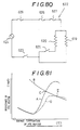
- the first and second PTC heaters have a resistance-temperature characteristics (curve A) that the heat is generated after turning on and the resistance is suddenly increased from the Curie point.
- curve A resistance-temperature characteristics
- the air stream is produced by the blower 614.
- the temperature of the first or second PTC heater is determined by the crossing point C of the resistance-temperature characteristic curve A with the operation curve B defined by the amount of the air produced by the blower, the temperature of the air sucked, and the like.
- the air blown out by the blower 614 to the leg of the user passes through either the heated first or second PTC heater 619 or 620.
- the air which has passed through the ventilating duct 604 is blown out as a relatively warm air from the lower portion of the toilet bowl 2 in the water closet 1 to the leg of the user (high operation).
- the air present in the toilet room 20 can contain the reduceing substances, such as hydrogen sulfide or ammonia formed from a detergent for the water closet 1.
- the PTC heaters 619 and 620 are exposed to the reducing substances, and then reduced therewith, the heaters do not exhibit the resistance elevation as the temperature elevation, as shown in Fig. 81 (curve D). In other words, the PTC heaters 619 and 620 lose the function to control the current as the temperature evevation, when reduced.
- the temperature of the reduced PTC heater 619 or 620 is elevated to the crossing point E of the operation curve B and the resistance-temperature characteristic curve D.
- the temperature fuse 626 or 627 arranged at the downstream area of the overheated heater is melted to turn the PTC heaters 619 and 620 off.
- the safety means or the temperature fuse 626 or 627 is melted to cease the application of the current to the PTC heaters 619 and 620. Therefore, dusts adsorbed to the PTC heaters do not ignite. Further, the uncomfortable feeling caused by the unusual heat generation can be avoided.
- the overheat generation can not be detected. This is because that some PTC heaters are reduced to generate the overheat, and a part of PTC heaters including the reduced PTC heaters as above is turned on, the temperature of the air heated thereby can be lower than that obtained by using all of the normal (not reduced) PTC heaters. Therefore, it is necessary to arrange the safety means (temperature fuse 626) for detecting the abnormal heat generation of the first PTC heater, and the safety means (temperature fuse 627) for the second PTC heater. If the first PTC heater is elevated to the predetermined temperature, when only the first PTC heater is operated (low operation), the abnormal heat generation of the first PTC can be detected.
- the safety means comprises the temperature fuses 626 and 627 connected with the first and seconf PTC heaters in series. Therefore, if one of the first and second PTC heaters generate the abnormal heat, both of the first and second PTC heaters are turned off.
- Fig. 82 illustrates the embodiment wherein the temperature fuses 626 and 627 are attached to the heat-resistant insulating material 614 supporting the first and second PTC heaters.
- the seat switch (which is turned on when the user sits down on the water closet) may be connected with the main switch in series.
- a deferring circuit for postphoning the start to operate the blower for a given period of time may be arranged, thereby preventing the cool air from blowing the user shortly after the seat switch is turned on. Further, after user stands up from the water closet, the blower may continue to operate for a given period of time, to thereby prevent the deformation of the ventilating duct with a remaining heat.
- a temperature sensor for detecting the temperature of the PTC heater may be used as the safety means instead of the temperature fuse. Using the temperature sensor, it is possible to control the current application to the PTC heater in accordance with the outlet from the sensor. Further, the current application can be controlled in accordance with the current amount or voltage of the PTC heater.
- a water closet unit comprising
- the above water closet unit brings about the following advantages.
- the operation of the wholly heating device is stopped, whereas the electric heater and the blower start to operate. Therefore, the heated air is blown out from the water closet or the portion around the closet to the leg of the user.
- the control is made to change the operation of the air-conditioner from the whole heating to the partial heating (electric heater), and vice versa.
- the wholly heating device is changed to the electric heater in the heating means, when the user enters the toilet room, the cool touch caused by the blown air having the low temperature can be avoided.
- the high temperature air heated with the electric heater is applied to the exposed leg of the user, whereby the user can be rapidly and concentratedly heated at the portion where the user feels particularly cold. Further, because the operation of the wholly heating device is stopped when the user is in the toilet room, the cool feeling can be avoided, whereby the user can enjoy a comfortable atmosphere from the entrance into the room to the exit therefrom.
- the electric heater is operated for a short period of time when the user is in the room, and the cost can be saved.
- the water closet 401 comprises, in addition to the leg heater 405 as the partially heating device for blowing the warm air out to the leg of the user, the heat pump type air-conditioner 403 for wholly heating all over the toilet room 20, and the control panel 406 for controlling the air-conditioner 403 and the leg heater 405.
- a cubic frame type adapter 49 of stainless steel is installed within the bay window unit 72 to contain and fix the air-conditioner 403 and the leg heater 405.
- the water closet 1 is attached thereto at the rear side of the closet with the bolts via a reinforced iron plate 726b.
- the bay window unit 72 contains therein toilet devices, such as the washing water tank 73, or the drainage pipe 56.
- the air-conditioner 403 serves as the wholly heating device in this embodiment, is a wind-fan type, and is contained in the cubic frame type adapter 49.
- the air-conditioner 403 is floatingly attached via a rubber mount 732 to a slide pan 731 fixed to the adapter 49 with bolts, whereby vibration of the water closet unit can be avoided by preventing transmission of vibration of the air-conditioner 403 to the bay window unit 72.
- a unit case 733 for the air-conditioner 430 is connected with the domestic electric source, and contains an electric box for supplying electric current to the air-conditioner 403 and the leg heater 405.
- the unit case 733 contains an inside air circulating duct 735 which is connected with the toilet room 20, and an outside air circulating duct 736 which is separated from the inside air circulating duct 735 with interstructures or the like and is connected with the outside of the toilet room 20.
- a refrigerating cycle of the air-conditioner 403 comprises a compressor 730a for a refrigeration medium, a heat exchanger 730b for the inside of the room, a heat exchanger 730c for the outside of the room, a four-direction valve 730d, a vacuum device (not shown), and refrigeration medium pipes (not shown) for connecting the above components with each other.
- the compressor 730a may compress the refrigeration medium sucked, and discharge the refrigeration medium with a high temperature and a high pressure.
- the heat exchanger 730b for the inside of the room is disposed within the inside air circulating duct 735, and serves as a condenser to cool and condense the refrigeration medium having a high temperature and a high pressure and supplied from the compressor 730a upon a heating operation.
- the heat exchanger 730c for the outside of the room is disposed within the outside air circulating duct 736, and serves as an evaporator to evaporate the refrigeration medium having a low temperature and a low pressure and supplied from the vacuum device by absorption of the heat from the atmosphere.
- the four-direction valve 730d changes the flow directions of the refrigeration medium, and the refrigeration cycle from the heating operation to the cooling operation, and vice versa.
- the vacuum device reduces the pressure of the refrigeration medium.
- the inside air circulating duct 735 contains the heat exchanger 730d for the inside of the room, and a blower 735a for the inside of the room.
- a blower 735a for the inside of the room.
- the filter 735b comprises a foam material which can adsorb the dust, and further may contain a deodorizer such as an activated carbon, an aromatic to neutrize the toilet odor, or the like.
- the outside air circulating duct 736 contains the heat exchanger 730c for the outside of the room, and a blower 736a for the outside of the room.
- a blower 736a for the outside of the room.
- a grill 733a is disposed to cover the intake vent 735c (having the filter 735b) and the outlet 735d.
- the leg heater 405 is attached to the reinforced iron plate 726b with bolts so that the warm air outlet 426a of the heater case 426 is connected with the inlet 426a of the warm air duct 4, at the rear end of the water closet 1.
- the seat switch 27 When the user enters the toilet room 20 and sits down on the toilet seat 22 on the water closet 1, the resistance of the seat switch 27 is changed by the weight of the user.
- the seat switch 27 is disposed under the toilet seat 22 of the water closet 1.
- the heating means is changed from the air-conditioner 403 to the PTC heater when the user enters the toilet room, and so, the cool touch caused by the warm air having a relatively low temperature and blown out from the air-conditioner can be avoided.
- the warm air heated by the PTC heater 453 and having a relatively high temperature is brought into contact with the exposed leg of the user, and so, the user is rapidly heated, concentratedly at the portion where the user particularly feels cool.
- the temperature in the toilet room 20 can be maintained if the operation of the air-conditioner 403 is stopped, whereby the user can enjoy the comfortable atmosphere from the entrance to the exit.
- the PTC heater 453 is operated for a relatively short period of time when the user is in the toilet room 20, the cost for the operation may be saved.
- the temperature when the toilet room is not employed is presetted to the level where the user does not feel warm, as well as cool, and the leg of the user can be heated when the seat switch is on.
- the cost saving may be improved.
- the present invention also relates to a prefabricated toilet room unit wherein the water closet unit is installed.
- the prefabricated toilet room unit can be manufactured by a conventional method, using the water closet unit as mentioned above.
Landscapes
- Engineering & Computer Science (AREA)
- Health & Medical Sciences (AREA)
- Public Health (AREA)
- Thermal Sciences (AREA)
- Physics & Mathematics (AREA)
- Chemical & Material Sciences (AREA)
- Combustion & Propulsion (AREA)
- Mechanical Engineering (AREA)
- General Engineering & Computer Science (AREA)
- Life Sciences & Earth Sciences (AREA)
- Hydrology & Water Resources (AREA)
- Water Supply & Treatment (AREA)
- Epidemiology (AREA)
- Bidet-Like Cleaning Device And Other Flush Toilet Accessories (AREA)
- Toilet Supplies (AREA)
- Sanitary Device For Flush Toilet (AREA)
Applications Claiming Priority (14)
| Application Number | Priority Date | Filing Date | Title |
|---|---|---|---|
| JP10094588A JPH01270834A (ja) | 1988-04-22 | 1988-04-22 | トイレ用暖房装置 |
| JP100945/88 | 1988-04-22 | ||
| JP107235/88 | 1988-04-28 | ||
| JP63107235A JPH0621463B2 (ja) | 1988-04-28 | 1988-04-28 | トイレ用暖房装置 |
| JP108064/88 | 1988-04-29 | ||
| JP63108064A JPH01281341A (ja) | 1988-04-29 | 1988-04-29 | トイレ用暖房装置 |
| JP1988060609U JPH0626599Y2 (ja) | 1988-05-10 | 1988-05-10 | 温風吹出型の洋風便器 |
| JP1988060610U JPH0643267Y2 (ja) | 1988-05-10 | 1988-05-10 | 温風吹出型の洋風便器の設置構造 |
| JP60609/88U | 1988-05-10 | ||
| JP60618/88U | 1988-05-10 | ||
| JP1988060612U JPH061651Y2 (ja) | 1988-05-10 | 1988-05-10 | 温風吹出型の洋風便器 |
| JP60610/88U | 1988-05-10 | ||
| JP60612/88U | 1988-05-10 | ||
| JP1988060618U JPH0612080Y2 (ja) | 1988-05-10 | 1988-05-10 | 温風吹出型の洋風便器の設置構造 |
Publications (2)
| Publication Number | Publication Date |
|---|---|
| EP0339883A1 true EP0339883A1 (de) | 1989-11-02 |
| EP0339883B1 EP0339883B1 (de) | 1991-09-25 |
Family
ID=27564992
Family Applications (1)
| Application Number | Title | Priority Date | Filing Date |
|---|---|---|---|
| EP89303990A Expired - Lifetime EP0339883B1 (de) | 1988-04-22 | 1989-04-21 | Wasserklosett mit Warmluftgebläse und Wasserklosetteinheit, befestigbar in einem Toilettenraum |
Country Status (5)
| Country | Link |
|---|---|
| US (1) | US5058217A (de) |
| EP (1) | EP0339883B1 (de) |
| KR (1) | KR900016559A (de) |
| DE (1) | DE68900280D1 (de) |
| ES (1) | ES2027064T3 (de) |
Families Citing this family (6)
| Publication number | Priority date | Publication date | Assignee | Title |
|---|---|---|---|---|
| US20060179556A1 (en) * | 2004-08-13 | 2006-08-17 | Carr Daniel R | Ventilated toilet system and method |
| KR100640689B1 (ko) * | 2004-10-08 | 2006-11-02 | (주)유아즈 | 침낭 |
| US9168199B2 (en) * | 2012-04-09 | 2015-10-27 | Jianhua Li | Household medicated-bath treatment device |
| US10669706B2 (en) | 2018-04-20 | 2020-06-02 | 3S Renovations, LLC | Toilet assemblies |
| US11382829B2 (en) * | 2020-01-10 | 2022-07-12 | Leiamoon LLC | Electronic steam seat |
| GB2636170A (en) * | 2023-12-01 | 2025-06-11 | Boss Cabins Ltd | Water closet cabin |
Citations (4)
| Publication number | Priority date | Publication date | Assignee | Title |
|---|---|---|---|---|
| US4071915A (en) * | 1975-01-09 | 1978-02-07 | Kuze Kurataro | Water closet seat warmer and ventilator |
| EP0105377A1 (de) * | 1982-03-17 | 1984-04-18 | Matsushita Electric Industrial Co., Ltd. | Toilettenanordnung |
| GB2137873A (en) * | 1983-04-11 | 1984-10-17 | Michael William Harfield | Chair heater |
| FR2593687A1 (fr) * | 1986-02-02 | 1987-08-07 | Capet Bernard | Siege chauffant |
Family Cites Families (16)
| Publication number | Priority date | Publication date | Assignee | Title |
|---|---|---|---|---|
| DE2456020C2 (de) * | 1974-11-27 | 1984-08-23 | Huenninghaus, Geb. Dick, Maria Magdalena, 7803 Gundelfingen | Vorrichtung zum Reinigen einer WC- Brille |
| US4028745A (en) * | 1976-05-21 | 1977-06-14 | Caniglia Joseph E | Sanitary spray-dry closet seat |
| DE2739181B2 (de) * | 1977-08-31 | 1979-07-19 | Ytong Ag, 8000 Muenchen | Verfahren zur Herstellung von hydrothermal gehärteten Gasbeton-Bauteilen, sowie Gasbeton-Bauteil |
| JPS5733642A (en) * | 1980-07-31 | 1982-02-23 | Matsushita Electric Works Ltd | Heated toilet stool |
| US4329745A (en) * | 1980-08-20 | 1982-05-18 | Lazaro Aguero | Automatic weight operated toilet flushing device |
| US4411030A (en) * | 1980-10-16 | 1983-10-25 | Aisin Seiki Kabushiki Kaisha | Apparatus for drying genitals and the posterior parts of human body |
| AU8247382A (en) * | 1981-04-14 | 1983-04-21 | Coles Cranes Ltd. | Telescopic booms for cranes |
| DE3380269D1 (en) * | 1982-03-17 | 1989-08-31 | Matsushita Electric Industrial Co Ltd | Sanitary cleaning device |
| US4451942A (en) * | 1982-09-15 | 1984-06-05 | Matsushita Electric Works, Ltd. | Local washing device of flush toilet |
| US4692951A (en) * | 1984-10-31 | 1987-09-15 | Toto Ltd. | Sanitary facility room for clean room |
| IE58641B1 (en) * | 1985-10-14 | 1993-10-20 | Cws Ag | Device for the automatic cleaning of a toilet seat |
| US4745639A (en) * | 1986-06-16 | 1988-05-24 | Wileman Industries, Inc. | Toilet apparatus with automatic self-cleaning means |
| JPS63104467A (ja) * | 1986-10-22 | 1988-05-09 | Hitachi Ltd | 半導体集積回路装置 |
| DE3641229A1 (de) * | 1986-12-02 | 1988-06-16 | Schering Ag | Trifluormethylsubstituierte azole, verfahren zu ihrer herstellung und ihre verwendung als mittel mit herbizider wirkung |
| US4831670A (en) * | 1987-03-23 | 1989-05-23 | Guadalupe Velasquez | Automatic flushing apparatus for toilets |
| JPS63311918A (ja) * | 1987-06-16 | 1988-12-20 | 株式会社デンソー | トイレ用温風暖房機 |
-
1989
- 1989-04-21 ES ES198989303990T patent/ES2027064T3/es not_active Expired - Lifetime
- 1989-04-21 EP EP89303990A patent/EP0339883B1/de not_active Expired - Lifetime
- 1989-04-21 DE DE8989303990T patent/DE68900280D1/de not_active Expired - Lifetime
- 1989-04-22 KR KR1019890005389A patent/KR900016559A/ko not_active Withdrawn
- 1989-04-24 US US07/342,031 patent/US5058217A/en not_active Expired - Fee Related
Patent Citations (4)
| Publication number | Priority date | Publication date | Assignee | Title |
|---|---|---|---|---|
| US4071915A (en) * | 1975-01-09 | 1978-02-07 | Kuze Kurataro | Water closet seat warmer and ventilator |
| EP0105377A1 (de) * | 1982-03-17 | 1984-04-18 | Matsushita Electric Industrial Co., Ltd. | Toilettenanordnung |
| GB2137873A (en) * | 1983-04-11 | 1984-10-17 | Michael William Harfield | Chair heater |
| FR2593687A1 (fr) * | 1986-02-02 | 1987-08-07 | Capet Bernard | Siege chauffant |
Also Published As
| Publication number | Publication date |
|---|---|
| KR900016559A (ko) | 1990-11-13 |
| EP0339883B1 (de) | 1991-09-25 |
| ES2027064T3 (es) | 1992-05-16 |
| US5058217A (en) | 1991-10-22 |
| DE68900280D1 (de) | 1991-10-31 |
Similar Documents
| Publication | Publication Date | Title |
|---|---|---|
| US5778147A (en) | Dew preventing device for air conditioners | |
| US5184355A (en) | Water closet blowing warm air and water closet unit attachable to toilet room | |
| US5058217A (en) | Water closet blowing warm air and water closet unit attachable to toilet room | |
| KR970001287B1 (ko) | 공기조화기의 제어장치 | |
| KR102132141B1 (ko) | 기차의 객실 내부 외기 유입방지장치 | |
| JPH05322312A (ja) | 温風暖房器 | |
| JP3561656B2 (ja) | スチーム発生付ストーブ | |
| JP2002061899A (ja) | 加湿機能付温風機 | |
| JP2624361B2 (ja) | 換気装置 | |
| JP2515057B2 (ja) | 空気浄化機能付空気調和機の制御装置 | |
| JPH11325601A (ja) | 空気清浄器付温風暖房機 | |
| JP3883712B2 (ja) | 浴室暖房ユニット | |
| GB2251681A (en) | Controlling a ventilator fan speed and heater output | |
| JPS5916748Y2 (ja) | 室内空気の汚染制御装置 | |
| JPS6328335Y2 (de) | ||
| JP3553352B2 (ja) | 蓄熱式暖房機 | |
| JPH01278629A (ja) | トイレ用暖房装置 | |
| JP2000130820A (ja) | 空気調和機 | |
| JPH089567Y2 (ja) | 電気温風機 | |
| JPH03217758A (ja) | 温風暖房機 | |
| JPH0534015A (ja) | 電気温風暖房機 | |
| JPH03217757A (ja) | 温風暖房機 | |
| JPH06272878A (ja) | 冷暖房システム | |
| KR19980014762A (ko) | 팬히터 제어방법 | |
| JPH05332593A (ja) | 空気調和機の制御方法 |
Legal Events
| Date | Code | Title | Description |
|---|---|---|---|
| PUAI | Public reference made under article 153(3) epc to a published international application that has entered the european phase |
Free format text: ORIGINAL CODE: 0009012 |
|
| AK | Designated contracting states |
Kind code of ref document: A1 Designated state(s): DE ES FR GB IT SE |
|
| 17P | Request for examination filed |
Effective date: 19900321 |
|
| 17Q | First examination report despatched |
Effective date: 19900718 |
|
| GRAA | (expected) grant |
Free format text: ORIGINAL CODE: 0009210 |
|
| AK | Designated contracting states |
Kind code of ref document: B1 Designated state(s): DE ES FR GB IT SE |
|
| REF | Corresponds to: |
Ref document number: 68900280 Country of ref document: DE Date of ref document: 19911031 |
|
| ITF | It: translation for a ep patent filed | ||
| ET | Fr: translation filed | ||
| REG | Reference to a national code |
Ref country code: ES Ref legal event code: FG2A Ref document number: 2027064 Country of ref document: ES Kind code of ref document: T3 |
|
| PLBE | No opposition filed within time limit |
Free format text: ORIGINAL CODE: 0009261 |
|
| STAA | Information on the status of an ep patent application or granted ep patent |
Free format text: STATUS: NO OPPOSITION FILED WITHIN TIME LIMIT |
|
| 26N | No opposition filed | ||
| PGFP | Annual fee paid to national office [announced via postgrant information from national office to epo] |
Ref country code: GB Payment date: 19940411 Year of fee payment: 6 |
|
| PGFP | Annual fee paid to national office [announced via postgrant information from national office to epo] |
Ref country code: ES Payment date: 19940412 Year of fee payment: 6 |
|
| PGFP | Annual fee paid to national office [announced via postgrant information from national office to epo] |
Ref country code: FR Payment date: 19940415 Year of fee payment: 6 |
|
| PGFP | Annual fee paid to national office [announced via postgrant information from national office to epo] |
Ref country code: DE Payment date: 19940418 Year of fee payment: 6 |
|
| PGFP | Annual fee paid to national office [announced via postgrant information from national office to epo] |
Ref country code: SE Payment date: 19940419 Year of fee payment: 6 |
|
| EAL | Se: european patent in force in sweden |
Ref document number: 89303990.9 |
|
| PG25 | Lapsed in a contracting state [announced via postgrant information from national office to epo] |
Ref country code: GB Effective date: 19950421 |
|
| PG25 | Lapsed in a contracting state [announced via postgrant information from national office to epo] |
Ref country code: SE Effective date: 19950422 Ref country code: ES Free format text: LAPSE BECAUSE OF NON-PAYMENT OF DUE FEES Effective date: 19950422 |
|
| GBPC | Gb: european patent ceased through non-payment of renewal fee |
Effective date: 19950421 |
|
| PG25 | Lapsed in a contracting state [announced via postgrant information from national office to epo] |
Ref country code: FR Effective date: 19951229 |
|
| PG25 | Lapsed in a contracting state [announced via postgrant information from national office to epo] |
Ref country code: DE Effective date: 19960103 |
|
| EUG | Se: european patent has lapsed |
Ref document number: 89303990.9 |
|
| REG | Reference to a national code |
Ref country code: FR Ref legal event code: ST |
|
| REG | Reference to a national code |
Ref country code: ES Ref legal event code: FD2A Effective date: 19990201 |
|
| PG25 | Lapsed in a contracting state [announced via postgrant information from national office to epo] |
Ref country code: IT Free format text: LAPSE BECAUSE OF NON-PAYMENT OF DUE FEES Effective date: 20050421 |