EP0348385A2 - Véhicule de lutte contre l'incendie - Google Patents
Véhicule de lutte contre l'incendie Download PDFInfo
- Publication number
- EP0348385A2 EP0348385A2 EP89890175A EP89890175A EP0348385A2 EP 0348385 A2 EP0348385 A2 EP 0348385A2 EP 89890175 A EP89890175 A EP 89890175A EP 89890175 A EP89890175 A EP 89890175A EP 0348385 A2 EP0348385 A2 EP 0348385A2
- Authority
- EP
- European Patent Office
- Prior art keywords
- tank
- vehicle frame
- extinguishing agent
- fire engine
- engine according
- Prior art date
- Legal status (The legal status is an assumption and is not a legal conclusion. Google has not performed a legal analysis and makes no representation as to the accuracy of the status listed.)
- Withdrawn
Links
- XLYOFNOQVPJJNP-UHFFFAOYSA-N water Substances O XLYOFNOQVPJJNP-UHFFFAOYSA-N 0.000 title description 3
- 239000000725 suspension Substances 0.000 claims description 15
- 239000003795 chemical substances by application Substances 0.000 description 44
- 108010066114 cabin-2 Proteins 0.000 description 3
- 230000005484 gravity Effects 0.000 description 3
- XAGFODPZIPBFFR-UHFFFAOYSA-N aluminium Chemical compound [Al] XAGFODPZIPBFFR-UHFFFAOYSA-N 0.000 description 2
- 229910052782 aluminium Inorganic materials 0.000 description 2
- 230000005540 biological transmission Effects 0.000 description 2
- 238000010276 construction Methods 0.000 description 2
- 238000012986 modification Methods 0.000 description 2
- 230000004048 modification Effects 0.000 description 2
- 230000002411 adverse Effects 0.000 description 1
- 230000015572 biosynthetic process Effects 0.000 description 1
- 230000002349 favourable effect Effects 0.000 description 1
- 230000000717 retained effect Effects 0.000 description 1
Images


Classifications
-
- A—HUMAN NECESSITIES
- A62—LIFE-SAVING; FIRE-FIGHTING
- A62C—FIRE-FIGHTING
- A62C27/00—Fire-fighting land vehicles
Definitions
- the invention relates to a tank fire truck with a driver's or crew cabin and a loading space as well as a front and at least one rear wheel axle carrying vehicle frame and with an extinguishing agent tank located deep in the space between the wheel axles.
- Such a tank fire-fighting vehicle is known from EP-A-252 202, wherein a low overall vehicle center of gravity is achieved by the deep-lying fire-fighting agent tank.
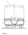
- the tank fire-fighting vehicle according to the invention of the type mentioned is characterized in that the extinguishing agent tank extends in cross section approximately U-shaped laterally and below the vehicle frame and is rotatably suspended from it.
- the above objective is met in an advantageous manner. Due to the rotating suspension of the extinguishing agent tank on the vehicle frame the latter can possibly twist within itself without the extinguishing agent tank being adversely affected; nonetheless, the extinguishing agent tank is attached at the height of the vehicle frame, which achieves the desired center of gravity as low as possible.
- the extinguishing agent tank is suspended on the vehicle frame at two points located one behind the other in the longitudinal direction of the vehicle frame.
- the rotatable suspension can, for example, by any elastic components, e.g. Spring bands, air springs or the like. Can be achieved.
- a particularly stable design for the extremely heavy extinguishing agent tank when fully filled is achieved, however, in that at least one suspension for the extinguishing agent tank forms or contains a swivel joint on the vehicle frame.
- the extinguishing agent tank is suspended from the vehicle frame by means of at least one cross member which extends across the vehicle frame and is connected to it, possibly rotatably, and to the extinguishing agent tank, for example by screwing. It is furthermore advantageous if, in the case of a vehicle frame formed from side members, for example like a ladder frame, the cross member is fixed with a yoke connected, for example screwed, which extends transversely between the two side members. On the other hand, it is also advantageous if, in the case of a vehicle frame designed as a tubular frame, the cross member has on its underside a partially circular-shaped recess in which the tubular frame is received.
- a pivot bearing for the tubular frame can be installed, but the crossbeam can also be firmly connected to the tubular frame, for example screwed, in order to achieve the rigid connection to the vehicle frame mentioned in this area .
- a structurally advantageous embodiment is also characterized in that in the case of a longitudinal beam, e.g. Formed in a ladder frame-like manner, the vehicle frame has the swivel joint attached to a yoke which connects the longitudinal members transversely, the swivel joint being connected to the extinguishing agent tank via two oblique struts which extend obliquely downwards and are fastened to the middle tank part below the vehicle frame.
- the extinguishing agent tank is pulled up on both sides of the vehicle frame at least over part of its length, in the area of the loading space, beyond the height of the vehicle frame. It is also favorable for this purpose if the extinguishing agent tank is recessed in the shape of a truncated pyramid in its front part and in its rear part, the transverse pyramid frustum side walls facing the center of the tank having an oblique course corresponding to a predetermined ramp angle.
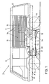
- the tank fire-fighting vehicle 1 illustrated in FIGS. 1 to 3 has, in a conventional manner, a driver's or team's cabin 2 in its front area and a device or cargo space 3 in its rear area, the basis for the cabin 2 or the loading space 3 is a vehicle frame 4, which also - via springs, not shown, for example Leaf springs or an air suspension - schematically arranged front and rear axles 5 and 6, with wheels 7 and 8, respectively.
- a relatively flat, cross-sectionally approximately U-shaped (see FIG. 3) extinguishing agent tank 9 is connected to the vehicle frame 4, which is arranged between the axes 5, 6 and has a gradation 10 at the top front, around a flat floor for the cabin 2 to enable.
- the top of the extinguishing agent tank 9, on the U-leg parts 11, 12 on both sides of the longitudinal center plane of the tank fire-fighting vehicle 1, has removable tank caps 13. These tank caps 13 are accessible from the loading space 3, for example after aluminum roller shutters 14 have been pushed up.
- These aluminum roller shutters 14 - for example two on each longitudinal side - close off the spaces for equipment on the side of an engine 15 and a manual transmission 16 located in front of it.
- the engine 15 and the transmission 16 are illustrated in FIG. 1 only very schematically with dashed lines in order to illustrate their position in the tank fire-fighting vehicle 1.
- a cardan shaft In front of the gearbox 16 a transfer case, not shown in the drawing, is provided a cardan shaft, also not shown, extends obliquely to the rear and another cardan shaft extends obliquely to the front, namely in the direction of the respective axis 5 or 6 of the tank fire-fighting vehicle 1 equipped here with all-wheel drive.
- oblique lines extend in the longitudinal center plane of the fire-fighting vehicle 1
- trough-shaped or conical surface-shaped depressions 17 and 18 are provided in the top of the U-web part 19 of the tank 9 (FIG. 2).
- the vehicle frame 4 is constructed according to FIGS. 1 to 3 from two parallel longitudinal beams 20, 21, for example C-shaped in cross section, which are made in a conventional manner by means of transverse struts (not shown) - cf. e.g. the aforementioned EP-A-252 202 - are connected to a lead frame.
- An extinguishing water pump (not shown in the drawing) can be fitted in the rear of the tank fire-fighting vehicle 1 and can be driven via an intermediate gear from the motor 15 arranged adjacent to it.
- the rear part of the fire engine 1 is closed at the rear end by means of a flap 22 (FIG. 1), which allows access to this fire water pump and to a conventional quick-action device, not shown, such as a 40 m long, rigid hose.
- the extinguishing agent tank 9 is suspended from the vehicle frame 4 in a specific manner, which will be explained below, the type of suspension now being based in particular on 2 and 3 to be explained.
- the extinguishing agent tank 9 is hung one behind the other on the vehicle frame 4 at two locations in the longitudinal direction of the vehicle, a rigid connection being provided between the extinguishing agent tank 9 and the vehicle frame 4 at the location of the rear suspension.
- This rigid connection is achieved in that a cross member 23 is provided (cf. 2 and 3 also Fig.
- a swivel joint generally indicated at 26
- which is of conventional design per se and which on the one hand has one or two transverse yokes (s) 27, that extends between the longitudinal beams 20 and 21 and is or are firmly connected to them, for example also by screwing, and on the other hand is coupled to two oblique struts 28, 29 which are connected to the extinguishing agent tank 9 are firmly connected to the U-web part 19 on the upper side thereof.
- connection or suspension with the built-in swivel joint 26 thus enables rotary movements at this point between the extinguishing agent tank 9 and the vehicle frame 4 when the latter twists, so that the extinguishing agent tank 9 nonetheless rigidly attached to the vehicle frame 4 via the parts 23, 24 and 25 does not cause any torsional stresses or the like.
- the extinguishing agent tank 9 has on its underside in its front part as well as in its rear part truncated pyramid-shaped depressions or trough parts 31 and 32, the transverse and oblique side walls facing each other and the center of the tank 33 or 34 of these tub parts one Have a slope that corresponds to the so-called ramp angle R (Fig. 1).
- This ramp angle is a predetermined size for the tank fire truck 1 and a measure of its ground clearance when driving over crests or the like.
- the tank volume can be increased, which is particularly important in the present case, since the tank content through the central channel-shaped recess of the tank in order to create space for the vehicle frame 4 (through this recess the approximately U-shaped cross section Shape of the tank 9 is obtained, see Fig. 3) the capacity of the tank is somewhat reduced.
- the extinguishing agent tank 9 in the area of the loading space 3 is, as illustrated, with the formation of the step 10 already mentioned, pulled upwards beyond the vehicle frame 4.
- the vehicle frame 4 in this embodiment is formed by a tubular frame 35, which is conventional per se and therefore does not require any further explanation.
- the cross-sectional shape of the extinguishing agent tank 9 is designed to conform to the tubular frame 35, and the extinguishing agent tank 9 is suspended from the tubular frame 35 by means of cross members 36, which have an arcuate recess 37 on their underside, with which they are on the top of the tubular frame 35 lie on.
- this cross member 36 can be firmly connected to the tubular frame 35, e.g. with the help of screws, and the cross member 36 is in turn laterally, for example via flanges not shown, with the extinguishing agent tank 9, i.e. the U-leg parts 11 and 12, screwed.
- the cross member 36 with its arcuate recess simply rest, if necessary with the interposition of bearings, on the tubular frame, which ensures the mobility.
Landscapes
- Health & Medical Sciences (AREA)
- Public Health (AREA)
- Business, Economics & Management (AREA)
- Emergency Management (AREA)
- Cooling, Air Intake And Gas Exhaust, And Fuel Tank Arrangements In Propulsion Units (AREA)
- Fire-Extinguishing By Fire Departments, And Fire-Extinguishing Equipment And Control Thereof (AREA)
- Body Structure For Vehicles (AREA)
- Aiming, Guidance, Guns With A Light Source, Armor, Camouflage, And Targets (AREA)
Applications Claiming Priority (2)
| Application Number | Priority Date | Filing Date | Title |
|---|---|---|---|
| AT1632/88 | 1988-06-23 | ||
| AT163288A AT395536B (de) | 1988-06-23 | 1988-06-23 | Tankloeschfahrzeug |
Publications (2)
| Publication Number | Publication Date |
|---|---|
| EP0348385A2 true EP0348385A2 (fr) | 1989-12-27 |
| EP0348385A3 EP0348385A3 (fr) | 1990-05-09 |
Family
ID=3517616
Family Applications (1)
| Application Number | Title | Priority Date | Filing Date |
|---|---|---|---|
| EP89890175A Withdrawn EP0348385A3 (fr) | 1988-06-23 | 1989-06-23 | Véhicule de lutte contre l'incendie |
Country Status (2)
| Country | Link |
|---|---|
| EP (1) | EP0348385A3 (fr) |
| AT (1) | AT395536B (fr) |
Cited By (1)
| Publication number | Priority date | Publication date | Assignee | Title |
|---|---|---|---|---|
| US5113946A (en) * | 1991-01-02 | 1992-05-19 | Cooper Grant S | Fire-fighting system |
Family Cites Families (7)
| Publication number | Priority date | Publication date | Assignee | Title |
|---|---|---|---|---|
| GB296445A (en) * | 1927-09-02 | 1928-11-15 | Welti Furrer A G A | Improvements in or relating to vehicle trailers |
| FR1134999A (fr) * | 1955-10-28 | 1957-04-23 | Vehicules Ind Titan Soc Nouv | Perfectionnement apporté aux citernes routières autoportantes, et véhicules analogues |
| FR2254206A5 (fr) * | 1973-12-07 | 1975-07-04 | Legueu Paul | |
| FR2358292A1 (fr) * | 1976-07-13 | 1978-02-10 | Stemat Sa | Vehicule a citerne incorporee |
| ZA853638B (en) * | 1984-05-18 | 1985-12-24 | Rosenbauer Kg Konrad | Chassis frame for service vehicles |
| DD228502A1 (de) * | 1984-11-12 | 1985-10-16 | Geol Erkundung Stendal Veb | Verbindung bei fahrzeugrahmen |
| EP0252202A1 (fr) * | 1986-07-07 | 1988-01-13 | Josef Hötzl | Voiture citerne pour la lutte contre l'incendie |
-
1988
- 1988-06-23 AT AT163288A patent/AT395536B/de not_active IP Right Cessation
-
1989
- 1989-06-23 EP EP89890175A patent/EP0348385A3/fr not_active Withdrawn
Cited By (1)
| Publication number | Priority date | Publication date | Assignee | Title |
|---|---|---|---|---|
| US5113946A (en) * | 1991-01-02 | 1992-05-19 | Cooper Grant S | Fire-fighting system |
Also Published As
| Publication number | Publication date |
|---|---|
| ATA163288A (de) | 1991-10-15 |
| AT395536B (de) | 1993-01-25 |
| EP0348385A3 (fr) | 1990-05-09 |
Similar Documents
| Publication | Publication Date | Title |
|---|---|---|
| EP0045889B1 (fr) | Véhicule articulé, en particulier autobus | |
| DE60008009T2 (de) | Einzelradaufhängung | |
| DE3751250T2 (de) | Geländefahrzeug mit Rädern mit integriertem Getriebe. | |
| DE7929072U1 (de) | Leichtfahrzeug | |
| DE2744578A1 (de) | Schlepper fuer eine terminalstation | |
| DE2151522A1 (de) | Fahrzeugachsaufhaengung | |
| DE1555975A1 (de) | Lagerung fuer eine kippbare Fahrerkanbine von Motorfahrzeugen | |
| EP0066269A2 (fr) | Barre d'attelage pour un train routier | |
| DE1530023A1 (de) | Fahrzeug | |
| DE2616101A1 (de) | Hinterradaufhaengung fuer ein einspuriges motorfahrzeug, insbesondere motorrad, mit einem kardanantrieb | |
| DE2741125A1 (de) | Lastkraftwagen, insbesondere grossraumfahrzeug oder sattelschlepper | |
| DE2062926C3 (de) | Gelenkiger Fahrzeugrahmen, insbesondere für geländegängige Fahrzeuge | |
| AT395536B (de) | Tankloeschfahrzeug | |
| DE2455226C2 (fr) | ||
| DE102012023571A1 (de) | Kippeinrichtung für kippbare Fahrerhäuser von Nutzfahrzeugen | |
| EP0011881B1 (fr) | Autobus à carrosserie articulée | |
| DE1806332A1 (de) | Vertauschbare Radaufhaengung bei Kraftfahrzeugen | |
| DE3340973A1 (de) | Kraftfahrzeug mit einem hilfsrahmen | |
| DE2011371C2 (de) | Einzelradaufhängung für einzeln antreibbare lenkbare Fahrzeugräder | |
| DE102011121262A1 (de) | Fahrzeug mit kompakter Einzelradaufhängung | |
| EP0252202A1 (fr) | Voiture citerne pour la lutte contre l'incendie | |
| DE3028007C2 (de) | Knickgelenktes Fahrzeug | |
| DE102004053121A1 (de) | Kraftfahrzeug mit Vierrad-Antrieb | |
| DE19527447C2 (de) | Lagerung eines Tanks auf einem Kraftfahrzeug-Chassis | |
| DE3518903C2 (fr) |
Legal Events
| Date | Code | Title | Description |
|---|---|---|---|
| PUAI | Public reference made under article 153(3) epc to a published international application that has entered the european phase |
Free format text: ORIGINAL CODE: 0009012 |
|
| AK | Designated contracting states |
Kind code of ref document: A2 Designated state(s): AT BE CH DE ES FR GB GR IT LI LU NL SE |
|
| PUAL | Search report despatched |
Free format text: ORIGINAL CODE: 0009013 |
|
| AK | Designated contracting states |
Kind code of ref document: A3 Designated state(s): AT BE CH DE ES FR GB GR IT LI LU NL SE |
|
| STAA | Information on the status of an ep patent application or granted ep patent |
Free format text: STATUS: THE APPLICATION IS DEEMED TO BE WITHDRAWN |
|
| 18D | Application deemed to be withdrawn |
Effective date: 19901112 |